
Review: Modellbau USA F-86D Dog Sabre
Greg Moore [email protected]
A turbine that's friendly to first-time jet pilots
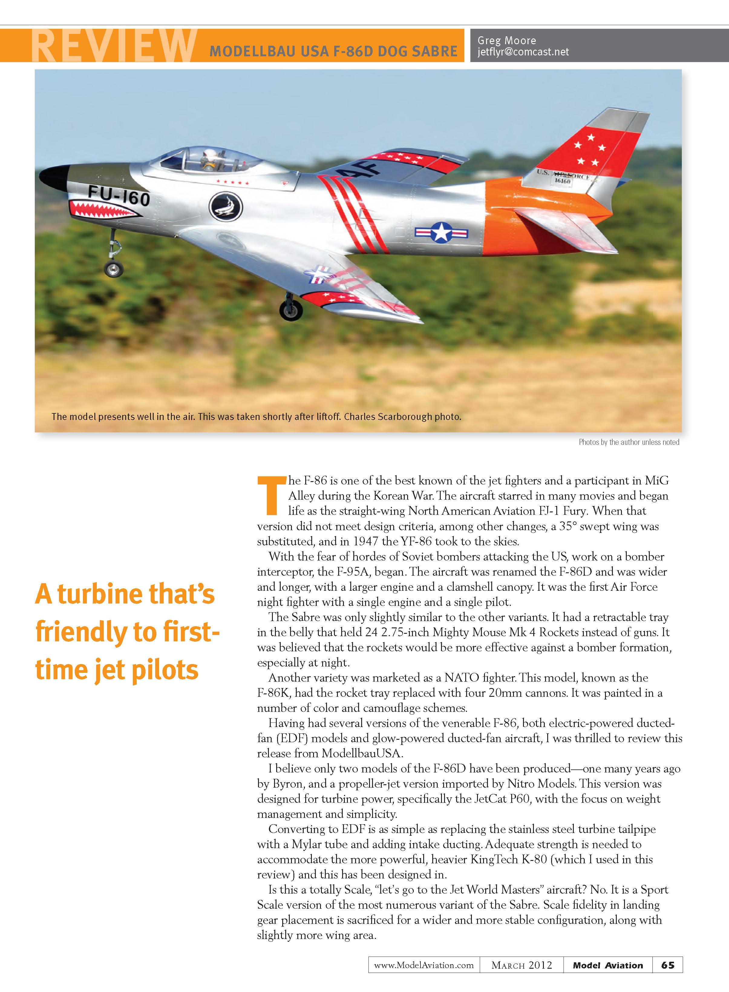
The F-86 is one of the best-known jet fighters and a familiar participant in MiG Alley during the Korean War. The aircraft starred in many movies and began life as the straight-wing North American Aviation FJ-1 Fury. When that version did not meet design criteria, among other changes a 35° swept wing was substituted, and in 1947 the YF-86 took to the skies.
With the fear of hordes of Soviet bombers attacking the U.S., work on a bomber interceptor—initially designated the F-95A—began. The aircraft was renamed the F-86D and was wider and longer, with a larger engine and a clamshell canopy. It was the first Air Force night fighter with a single engine and a single pilot.
The Sabre D was only slightly similar to other F-86 variants. It had a retractable belly tray that held 24 2.75-inch Mighty Mouse Mk 4 rockets instead of guns; the rockets were believed to be more effective against bomber formations, especially at night.
Another variety, marketed to NATO, was the F-86K. It replaced the rocket tray with four 20mm cannons and was painted in several color and camouflage schemes.
Having built several versions of the venerable F-86—both electric ducted-fan (EDF) and glow-powered ducted-fan—I was thrilled to review this release from ModellbauUSA.
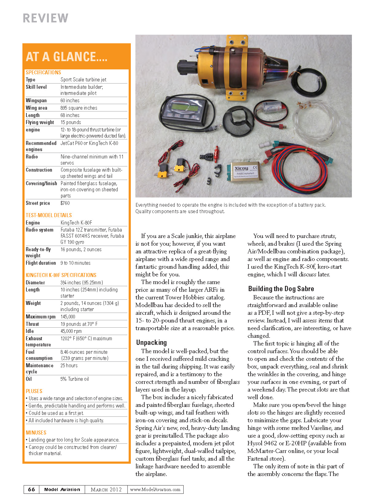
To my knowledge only two F-86D models had been produced previously—one many years ago by Byron and a propeller-jet version imported by Nitro Models. This ModellbauUSA version was designed for turbine power, specifically the JetCat P60, with emphasis on weight management and simplicity. Converting to EDF is straightforward: replace the stainless-steel turbine tailpipe with a Mylar tube and add intake ducting. Adequate strength is provided to accommodate more powerful, heavier engines such as the KingTech K-80 (which I used for this review).
Is this a totally scale, “let’s go to the Jet World Masters” aircraft? No. It is a sport-scale version of the most numerous Sabre variant. Scale fidelity in landing gear placement is sacrificed for a wider, more stable configuration and slightly more wing area. If you are a scale purist, this airplane is not for you; however, if you want an attractive replica of a great-flying airplane with a wide speed range and excellent ground handling, this might be ideal.
The model is roughly the same price as many larger ARFs in the Tower Hobbies catalog. Modellbau has chosen to sell the aircraft—designed around 15- to 20-pound-thrust engines—in a transportable size at a reasonable price.
Unpacking
The model is well packed. The one I received had mild cracking in the tail from shipping; it was easily repaired and is a testament to the correct strength and number of fiberglass layers used in the layup.
The box includes:
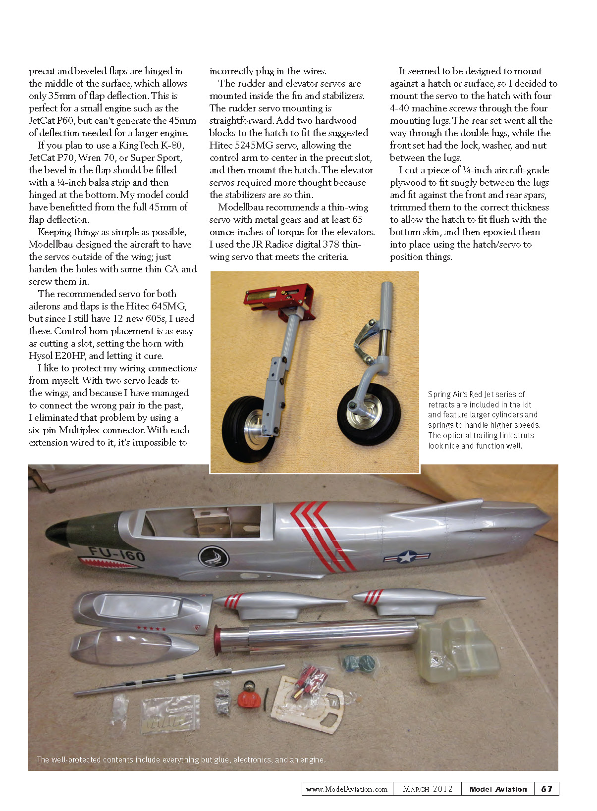
- A nicely fabricated and painted fiberglass fuselage
- Sheeted built-up wings and tail feathers with iron-on covering and stick-on decals
- Preinstalled Spring Air red heavy-duty landing gear
- A prepainted modern jet pilot figure
- A lightweight, dual-walled tailpipe
- Custom fiberglass fuel tanks
- All linkage hardware needed to assemble the airplane
You will need to purchase struts, wheels, and brakes (I used the Spring Air/Modellbau combination package), and engine and radio components. I used the KingTech K-80f kero-start engine, which I discuss later.
Building the Dog Sabre
Because the instructions are straightforward and available online as a PDF, I will not provide a step-by-step build. Instead, I’ll highlight items that need clarification, are interesting, or differ from typical builds.
Hinging control surfaces: You should be able to unpack, seal and shrink the covering wrinkles, and hinge all surfaces in an evening (or part of a weekend day). The precut slots are well done. Be sure to open/bevel the hinge slots so the hinges are slightly recessed to minimize gaps. Lubricate hinges with some melted Vaseline and use a good, slow-setting epoxy such as Hysol 9462 or E-20HP.
Flaps: The precut and beveled flaps are hinged in the middle of the surface, which allows only 35 mm of flap deflection. This is perfect for a small engine like the JetCat P60, but cannot generate the 45 mm of deflection needed for a larger engine. If you plan to use a KingTech K-80, JetCat P70, Wren 70, or Super Sport, fill the bevel in the flap with a 1/4-inch balsa strip and hinge at the bottom to obtain the full 45 mm of deflection. My model could have benefited from the full 45 mm.
Servos and wiring: Modellbau designed the servos outside the wing to keep things simple; harden the servo holes with thin CA and screw them in. The recommended servo for both ailerons and flaps is the Hitec 645MG. I used Hitec 605s I had on hand. Control horn placement is easy—cut a slot, set the horn with Hysol E-20HP, and let it cure.
To avoid plugging errors with wing servo leads, I used a six-pin Multiplex connector; with each extension wired to it, it’s impossible to plug the wrong pair into the receiver.
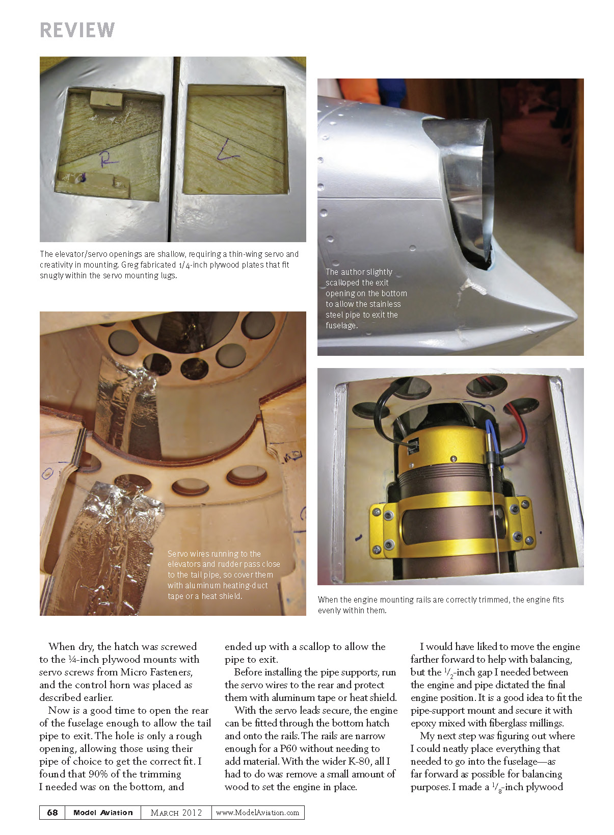
Tail servos: The rudder and elevator servos mount inside the fin and stabilizers. Rudder servo mounting is straightforward—add two hardwood blocks to the hatch to fit the suggested Hitec 5245MG so the control arm centers in the precut slot, then mount the hatch. Elevator servos required more thought because the stabilizers are thin. Modellbau recommends a thin-wing servo with metal gears and at least 65 oz-in of torque for the elevators. I used JR Radios digital 378 thin-wing servos that meet this criterion.
Mount the elevator servo to the hatch with four 4-40 machine screws through the servo’s mounting lugs. I cut a piece of 1/4-inch aircraft-grade plywood to fit snugly between the lugs and against the front and rear spars, trimmed it to allow the hatch to sit flush with the bottom skin, and epoxied it into place using the hatch/servo to position things. When dry, screw the hatch to the plywood mounts with servo screws and install the control horn as described earlier.
Engine and tailpipe: Open the rear of the fuselage enough to allow the tailpipe to exit. The hole is a rough opening to allow fitting different pipes; most trimming is on the bottom, and I ended up cutting a scallop to allow the pipe to exit cleanly. Before installing pipe supports, run the servo wires to the rear and protect them with aluminum tape or heat shield. With the servo leads secure, fit the engine through the bottom hatch onto the rails. The rails are narrow enough for a P60; with the wider K-80 I removed a small amount of wood to set the engine in place.
I would have liked to move the engine farther forward to help balance, but a 1/2-inch gap required between engine and pipe dictated final engine position. Fit the pipe-support mount and secure it with epoxy mixed with fiberglass millings.
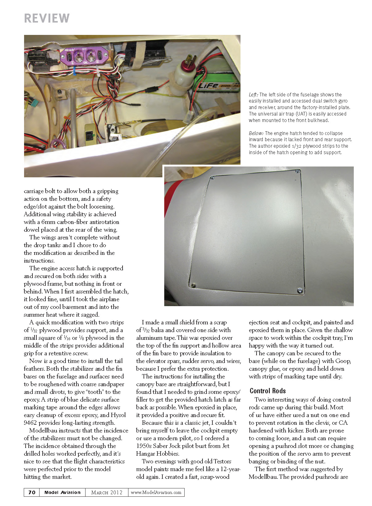
Equipment layout and balance: Place everything as far forward as possible. I made a 1/8-inch plywood plate that screwed into 1/4-inch plywood blocks and used the installed mounting plates to attach the Spring Air retract valve and dual switch. The switch is robust, snaps into on/off positions, and has charge leads. I mounted the ECU to a plywood plate epoxied to the bottom of the fuselage for easy connection to the ground-support unit and to monitor start data.
I use dual receiver packs with separate switches into separate ports on my jets. Space was needed for a pair of Hobbico LiFe 6.6 V, 2100 mAh packs and the provided 9.9 V A123-LiFe pump pack; these were placed as far forward as possible. The receiver packs can be mounted with Velcro alongside the nose gear rails, and the pump pack can be mounted with the retract air tank above the inlet in the radome.
Fuel tanks and routing: The large forward space becomes small quickly when assembling the fuel tanks. I opened the existing hole in the bulkhead to allow the fuel tank cap and lines to pass through smoothly and trimmed about 3/8 inch from the flange on top of the fuselage to allow the tanks to enter. A thin plywood piece beneath the inside edge of the tanks made them fit flush with the fuselage sides. Use Goop, PFM, or another silicone adhesive between tanks and sides to keep them in place. With two tubular spars running through the fuselage, secure servo leads and fuel/air lines with keepers or attachments.
Landing gear and wheel wells: Mount the Spring Air struts into their retract units, set some toe-in, and slowly retract to avoid them smashing into the top skin. I removed some wing rib material and shimmed the landing gear to prevent wedging against the top of the wing. Make wheel-well inserts to keep large masses of air out of the wing—an empty cereal box trimmed to shape and glued with medium CA works well; a coat of thinned epoxy adds fuel and water protection.
Wing attachment: To secure the wings to the fuselage, carefully measure and drill a hole for a 1/4-20 bolt. A thumbscrew could be used if you have small hands. I inserted a carriage bolt with the head removed into the blind nut in the wing and secured it with blue threadlocker; this bolt goes into the fuselage and through a 1/4-inch wheel collar that is secured within a plywood block and epoxied to the fuselage side. An 8-32 bolt substitutes for the setscrew and a flat slot is cut into the carriage bolt to provide gripping action and a safety edge/slot against loosening. Additional wing stability is achieved with a 6 mm carbon-fiber antirotation dowel placed at the rear of the wing.
Drop tanks: The wings aren't complete without the drop tanks; I modified them as described in the instructions.
Engine hatch: The engine access hatch is supported and secured on both sides with a plywood frame, but nothing in front or behind. In summer heat the hatch sagged slightly; I added two strips of 1/32-inch plywood for support and a small square of 1/16- or 1/8-inch plywood in the middle for additional grip and a retentive screw.
Tail feathers: Install the stabilizer and fin after roughening the bases with coarse sandpaper and small divots to give tooth to the epoxy. Wrap a strip of blue delicate-surface masking tape around the edges to allow easy cleanup of excess epoxy. Use Hysol 9462 for long-lasting strength. Modellbau instructs that the incidence of the stabilizers must not be changed—the drilled holes provided the correct incidence and the flight behavior confirmed the factory setup.
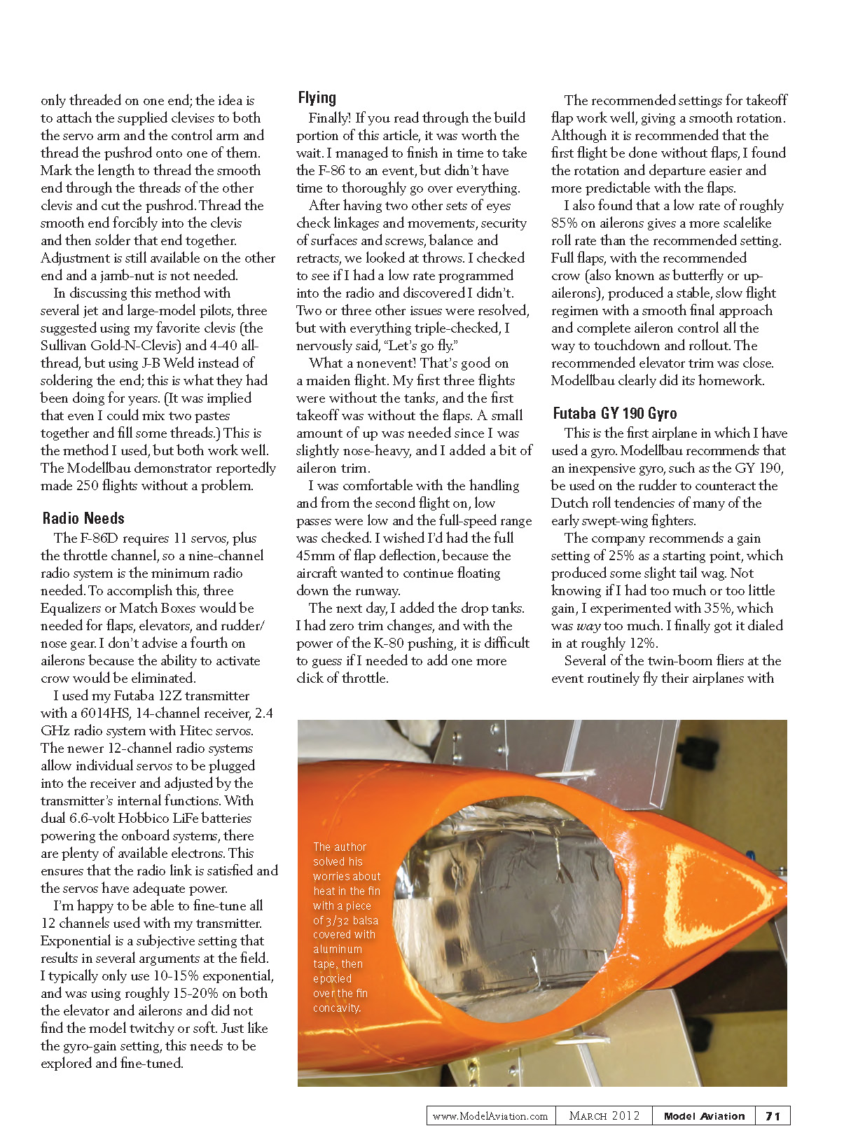
I made a small shield from 3/32-inch scrap balsa covered on one side with aluminum tape and epoxied it over the top of the fin support hollow area to provide insulation for the elevator spars, rudder servo, and wires.
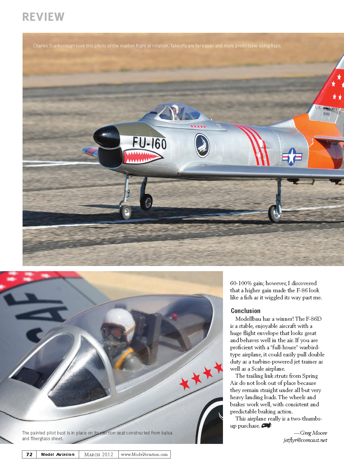
Canopy and cockpit: Installing the canopy base is straightforward; I ground some epoxy/filler to get the provided hatch latch as far back as possible. When epoxied in place it provided a positive fit. Because this is a classic jet, I ordered a 1950s Saber Jock pilot bust from Jet Hangar Hobbies. Two evenings with Testors paints produced a suitable pilot and a fast scrap-wood ejection seat and cockpit, which I epoxied into the shallow cockpit tray. The canopy can be secured to the base (while on the fuselage) with Goop, canopy glue, or epoxy and held down with masking tape until dry.
Control Rods
Two interesting approaches to control rods came up during the build. Common methods—using a nut on one end to prevent clevis rotation or CA hardening with kicker—can come loose or require enlarging pushrod slots.
Modellbau’s method: The provided pushrods are only threaded on one end. Attach supplied clevises to both the servo arm and control arm, thread the pushrod onto one clevis, mark the length to thread the smooth end through the threads of the other clevis, cut the pushrod, force the smooth end into the second clevis, and solder that end together. Adjustment remains available on the other end and a jam nut is not needed. The Modellbau demonstrator reportedly made 250 flights without a problem.
Alternate method I used: Many large-model pilots suggested using a Sullivan Gold-N-Clevis and 4-40 all-thread, but bonding the smooth end into the clevis with J-B Weld instead of soldering. This offers strong, permanent retention and has worked well for years.
Radio Needs
The F-86D requires 11 servos plus the throttle channel, so a nine-channel radio is the minimum system needed. To accomplish full function with nine channels you would need three Equalizers or Match Boxes for flaps, elevators, and rudder/nose gear. I do not advise a fourth unit on the ailerons because that would eliminate the ability to activate crow.
I used a Futaba 12Z transmitter with a 6014HS 14-channel receiver (2.4 GHz) and Hitec servos. Newer 12-channel radios allow individual servos to be plugged into the receiver and adjusted via transmitter functions. Dual 6.6 V Hobbico LiFe batteries provided onboard power and the provided 9.9 V pump pack powered the pump; there are plenty of available electrons for the servos and receiver.
I was able to fine-tune all 12 channels. Exponential is subjective—I typically use 10–15% exponential; for this ship I used roughly 15–20% on both elevator and ailerons and did not find the model twitchy or soft. As with gyro gain, these settings need exploration and fine-tuning.
Flying
Finally—flying! I finished the build in time to bring the F-86 to an event, though I didn’t have time for an exhaustive preflight check. After two other sets of eyes checked linkages, surface security, balance, and retracts, we checked throws. I discovered I had no low rates programmed; a couple of minor issues were resolved, and with everything triple-checked, I nervously said, “Let’s go fly.”
The maiden was a nonevent—that’s good. My first three flights were without the tanks; the first takeoff was without flaps. A small amount of up trim was needed since I was slightly nose-heavy, and I added a bit of aileron trim. Handling was comfortable, and from the second flight on low passes were low and the full-speed range was checked.
I wished I had the full 45 mm of flap deflection because the aircraft tended to float on landing with only 35 mm. The next day I added the drop tanks and had zero trim changes; with the K-80’s power it was hard to notice a difference in thrust demand.
Takeoff flaps: The recommended takeoff-flap settings work well, giving a smooth rotation. Although the instructions recommend the first flight be done without flaps, I found rotation and departure easier and more predictable with the flaps installed.
Aileron rates: I found a low rate of roughly 85% on ailerons gives a more scale-like roll rate than the recommended setting. Full flaps with the recommended crow (butterfly/up-ailerons) produced a stable, slow-flight regimen with a smooth final approach and complete aileron control through touchdown and rollout. The recommended elevator trim was close—Modellbau clearly did its homework.
Futaba GY 190 Gyro
This was my first airplane using a gyro. Modellbau recommends an inexpensive gyro such as the Futaba GY 190 on the rudder to counteract Dutch roll tendencies of many early swept-wing fighters.
The company suggests a gain of 25% as a starting point, which produced slight tail wag in my airplane. I tested 35% (way too much) and eventually settled around 12%. Some pilots routinely fly with 60–100% gain on twin-boom aircraft, but higher gain made the F-86 look like a fish as it wiggled past me. Low gain gave the best, most natural handling for this model.
Conclusion
Modellbau has a winner. The F-86D is a stable, enjoyable aircraft with a huge flight envelope that looks great and behaves well in the air. If you are proficient with a “full-house” warbird-type airplane, it could easily pull double duty as a turbine-powered jet trainer as well as a sport-scale model.
The trailing-link Spring Air struts remain straight under all but very heavy landing loads and do not look out of place. The wheels and brakes work well with consistent and predictable braking action.
This airplane is a two-thumbs-up purchase.
— Greg Moore [email protected]
Sources
- Modellbau USA
(954) 224-1700 www.modellbauusa.com
- KingTech Turbines
(626) 793-4677 www.kingtechturbines.com
- JetCat USA
(805) 226-8700 www.jetcatusa.com
- Spring Air Products
(321) 728-9002 www.retracts.com
- Jet Hangar Hobbies
(562) 467-0260 www.jethangar.com
- McMaster-Carr
(562) 462-4277 www.mcmaster.com
- Micro Fasteners
(800) 892-6917 www.microfasteners.com
- Valley View RC
(253) 875-6890 www.valleyviewrc.com
- Tower Hobbies
(800) 637-6050 www.towerhobbies.com
Transcribed from original scans by AI. Minor OCR errors may remain.

