
Rhom-Bus
By Ferrell Papic
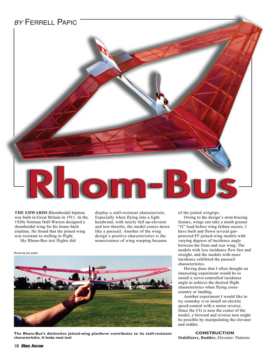
The Edwards rhomboidal biplane was built in Great Britain in 1911. In the 1920s Norman Hall‑Warren designed a rhomboidal (joined) wing for his home‑built airplane and found the joined wing to be resistant to stalling in flight.
My Rhom‑Bus test flights displayed a stall‑resistant characteristic. Especially when flying into a light headwind, with nearly full up‑elevator and low throttle, the model comes down like a parasail. Another positive characteristic of the joined‑wing design is the near‑elimination of wing warping because of the joined wingtips. Owing to the design's strut‑bracing feature, the wings can take a much greater "G" load before wing failure occurs.
I have built and flown several gas‑powered FF joined‑wing models with varying degrees of incidence angle between the front and rear wings. Models with less incidence flew fast and straight; models with more incidence exhibited the parasail characteristic. Having done that, I often thought an interesting experiment would be to install a servo‑controlled incidence angle to achieve different flight characteristics during cross‑country flight or landing. Another experiment I would like to try someday is installing an electric speed control with motor reverse. Since the CG is near the center of the model, forward and reverse turns might be possible by manipulating elevator and rudder.
CONSTRUCTION
Stabilizers, Rudder, Elevator: Patterns
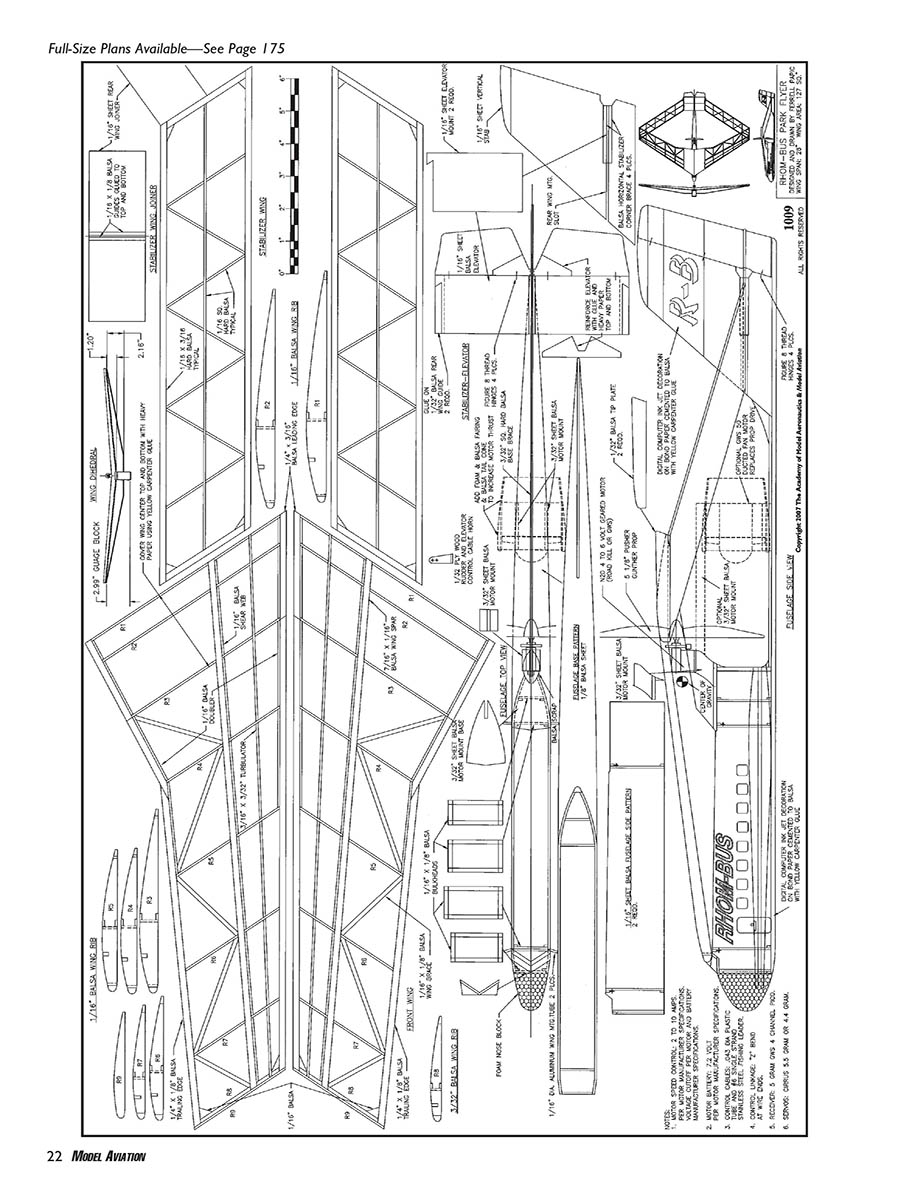
- Patterns of the stabilizer parts are provided on the drawing plans.
- Assemble the 1/16" balsa horizontal stabilizer on the vertical stabilizer using a square and corner braces.
- Install 1/32" balsa wing guides on the underside of the horizontal stabilizer.
- Install 1/32" plywood control horns on the rudder and elevator.
- Attach the rudder and elevator to the stabilizers with figure‑8 thread hinges.
Fuselage: Patterns
- Patterns of the fuselage parts are provided on the drawing plans.
- Assemble the 1/16" balsa bulkheads; cut the 1/8" balsa fuselage base and mount the 3/32" balsa base brace.
- Match‑drill the holes in the fuselage sides for the 1/16"‑diameter aluminum wing‑mounting tubes. Install and drill doublers inside the fuselage at the tube mounting holes.
- Since the Rhom‑Bus's CG is near the middle of the airplane, a GWS 40 or 50 electric ducted‑fan can be installed in place of a propeller drive. Recommended ducted‑fan motor batteries range from 550 mAh to 1200 mAh 7.4‑volt Li‑Poly packs.
- Assemble the fuselage, 1/16" balsa windshield, stabilizer assembly, motor‑mount base, and motor mount.
- Shape the motor‑mount doublers using sandpaper glued to a wood dowel.
- Rough out the foam nose block and glue it in place with yellow carpenter's glue. After the glue dries, final‑shape the nose block with a sanding block.
- Paint and decorate the fuselage, then install the 1/16"‑diameter wing‑mounting aluminum tubes.
Power options:
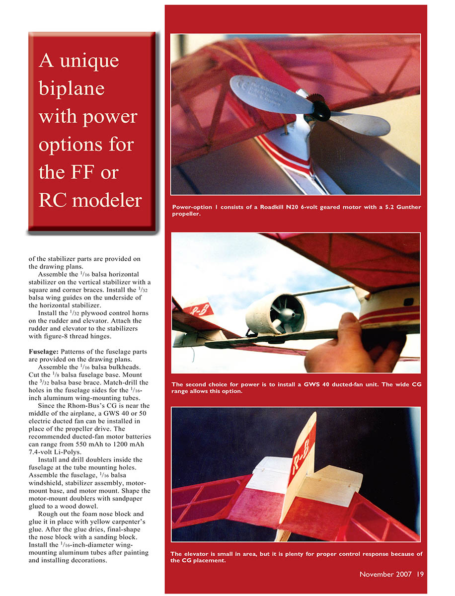
- Option 1: Roadkill N20 6‑volt geared motor with a 5.2" Gunther propeller.
- Option 2: GWS 40 ducted‑fan unit.
Note: The elevator is small in area but adequate because of the CG placement. The wide CG range allows either power option.
Wing
- The wing‑rib pattern is shown on the plans with spars, leading edges (LEs), and trailing edges (TEs) for reference.
- The front wings are joined with 1.2" of dihedral on each wingtip. The rear wings are joined with 2.16" of dihedral on each wingtip. Those amounts are recommended when flying in an enclosed gymnasium space.
- The rear wing joiner requires 1/32" balsa guides attached to the center top and bottom so it aligns properly in the vertical‑stabilizer slot.
- Cover the front wing center‑section with heavy paper adhered with a light application of yellow carpenter's glue.
- I covered my wings with red Reynolds Plastic Wrap using water‑thinned RC/56 canopy cement on the wing edges and centers. This material will heat‑shrink but can be damaged by excessive heat.
- It is best to join the front and rear wings after the fuselage is complete: slide the rear wing into the vertical‑stabilizer slot, then install the front wing with wing‑mounting rubber bands.
- Use 90° 2.99" high‑gauge blocks to align the wingtips so they are parallel. Then join the front wingtips to the rear wingtips and add 1/32" balsa wingtip plates for a finishing touch.
Structure notes:
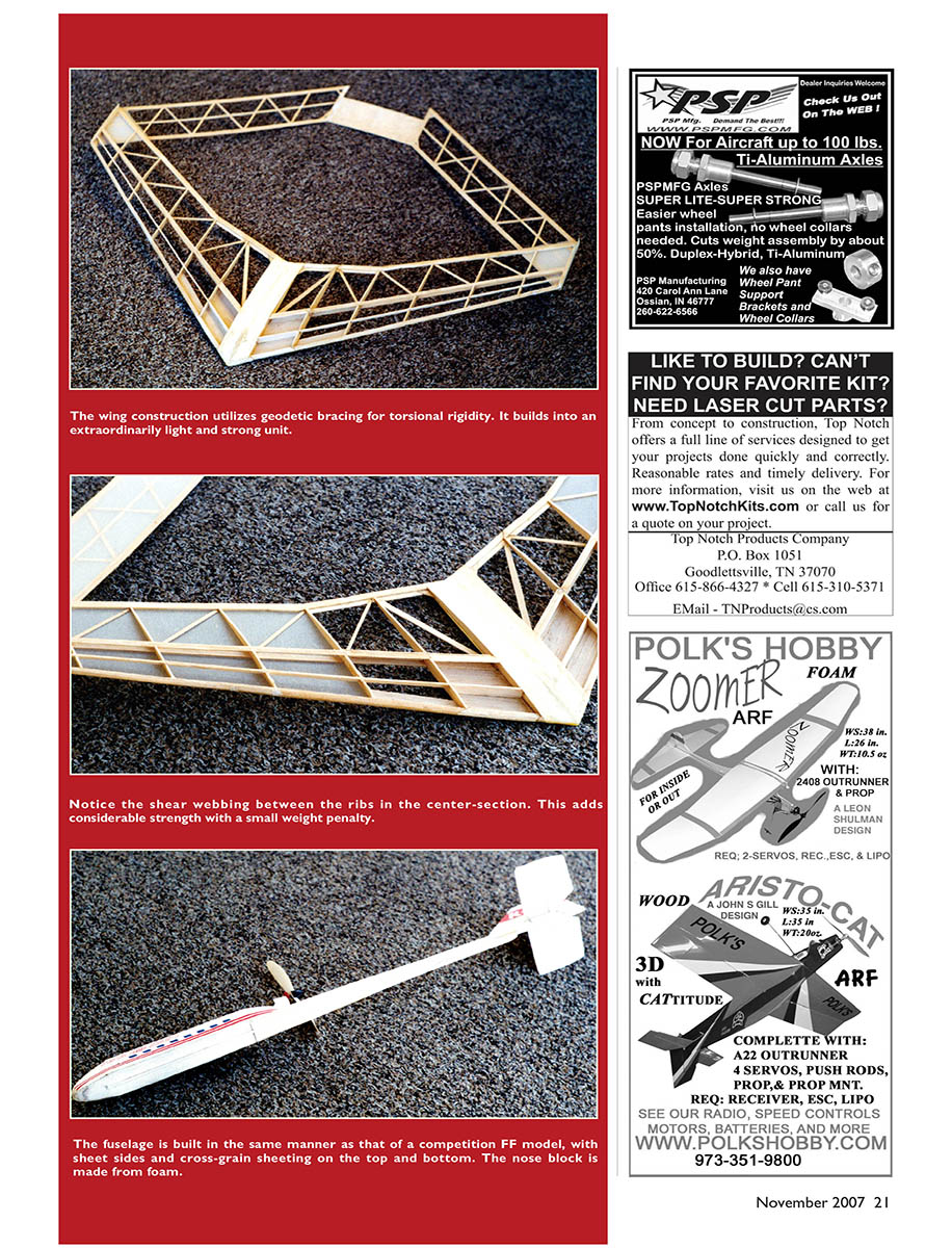
- The wing construction utilizes geodetic bracing for torsional rigidity; it builds into an extraordinarily light and strong unit.
- Notice the shear webbing between the ribs in the center‑section — this adds considerable strength with a small weight penalty.
- The fuselage is built much like a competition FF model, with sheet sides and cross‑grain sheeting on the top and bottom. The nose block is foam.
Finishing
- Spray a light coat of white latex model paint on the fuselage and stabilizers.
- Decorate the fuselage sides and vertical stabilizer with computer ink‑jet artwork on bond paper, adhered with a light application of yellow carpenter's glue.
- Contact me by e‑mail if you would like a copy of the digital Windows Metafile artwork.
Radio Installation
- Receiver/servos/speed control used: GWS 5‑gram, four‑channel GWR‑4P FM receiver; 5‑gram GWS Pico servos; and a GWS 2‑amp speed control.
- Control linkages: .043"‑diameter plastic tube with #6 .015"‑diameter single‑strand stainless‑steel fishing leader wire, using Z‑bend connections to servos and control horns.
- Use two‑pin Deans gold‑plated connectors on the battery‑pack and radio‑gear connections.
- Charging: conventional 8.4‑volt, 150 mAh NiMH batteries can be charged with a Watt‑Age pulse charger. Charge 7.2‑volt, 250 mAh Li‑Poly batteries only with a dedicated voltage‑cutoff charger (for example, a Poteski unit).
- Adjust battery and radio‑gear location in the fuselage to achieve the correct CG indicated on the plans. Visually check the underside of the wing center at arm’s length for left/right symmetry, then check all servos for reversed controls.
Flying
- Launch technique: hold the model in your left hand and place your right thumb on the transmitter control stick from the beginning of the flight.
- Make transmitter‑stick trim adjustments until the model flies straight and level with hands‑off control.
- Outdoor flying is best in no wind or moderate wind conditions. Indoor flying is suitable anytime.
Contact: Ferrell Papic [email protected]
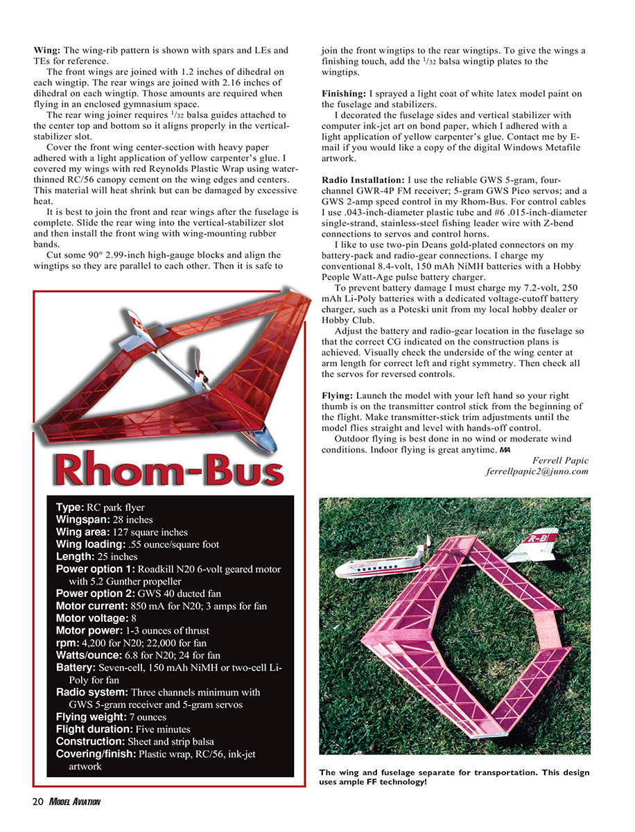
- Type: RC park flyer
- Wingspan: 28 inches
- Wing area: 127 square inches
- Wing loading: 0.55 ounce/square foot
- Length: 25 inches
- Power option 1: Roadkill N20 6‑volt geared motor with 5.2" Gunther propeller
- Power option 2: GWS 40 ducted fan
- Motor current: 850 mA for N20; 3 A for fan
- Motor voltage: 8 V
- Thrust: 1–3 ounces
- RPM: 4,200 for N20; 22,000 for fan
- Watts/ounce: 6.8 for N20; 24 for fan
- Battery: seven‑cell, 150 mAh NiMH or two‑cell Li‑Poly for fan
- Radio system: three channels minimum with GWS 5‑gram receiver and 5‑gram servos
- Flying weight: 7 ounces
- Flight duration: five minutes
- Construction: sheet and strip balsa
- Covering/finish: plastic wrap, RC/56, ink‑jet artwork
Transcribed from original scans by AI. Minor OCR errors may remain.

