
Right Angle
by Dick Sarpolus
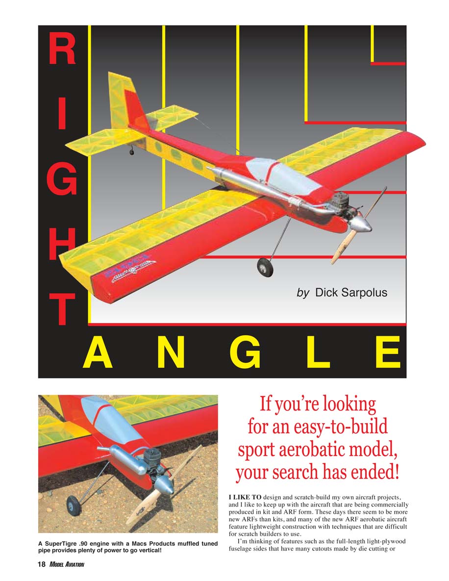
If you’re looking for an easy-to-build sport aerobatic model, your search has ended!
I like to design and scratch-build my own aircraft projects, and I like to keep up with the aircraft that are being commercially produced in kit and ARF form. These days there seem to be more new ARFs than kits, and many of the new ARF aerobatic aircraft feature lightweight construction with techniques that are difficult for scratch builders to use. I’m thinking of features such as the full-length light-plywood fuselage sides that have many cutouts made by die cutting or laser cutting. Modelers could get large sheets of the light plywood, lay out similar weight-saving cutout patterns, and make the cutouts with a scroll saw, a coping saw, or a Dremel tool, but it would be a long process for one scratch-built aircraft—a process I wouldn’t want to go through.
I could substitute a built-up structure, but, again, I don’t look forward to the cut-the-sticks-and-glue process and prefer to work with sheet balsa rather than light plywood. I would also think that some of those extra-light ARFs would be fragile for everyday fun use, and I want an airplane that can handle a reasonable amount of bouncing around.
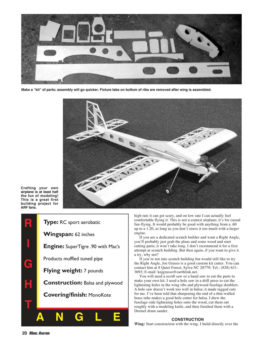
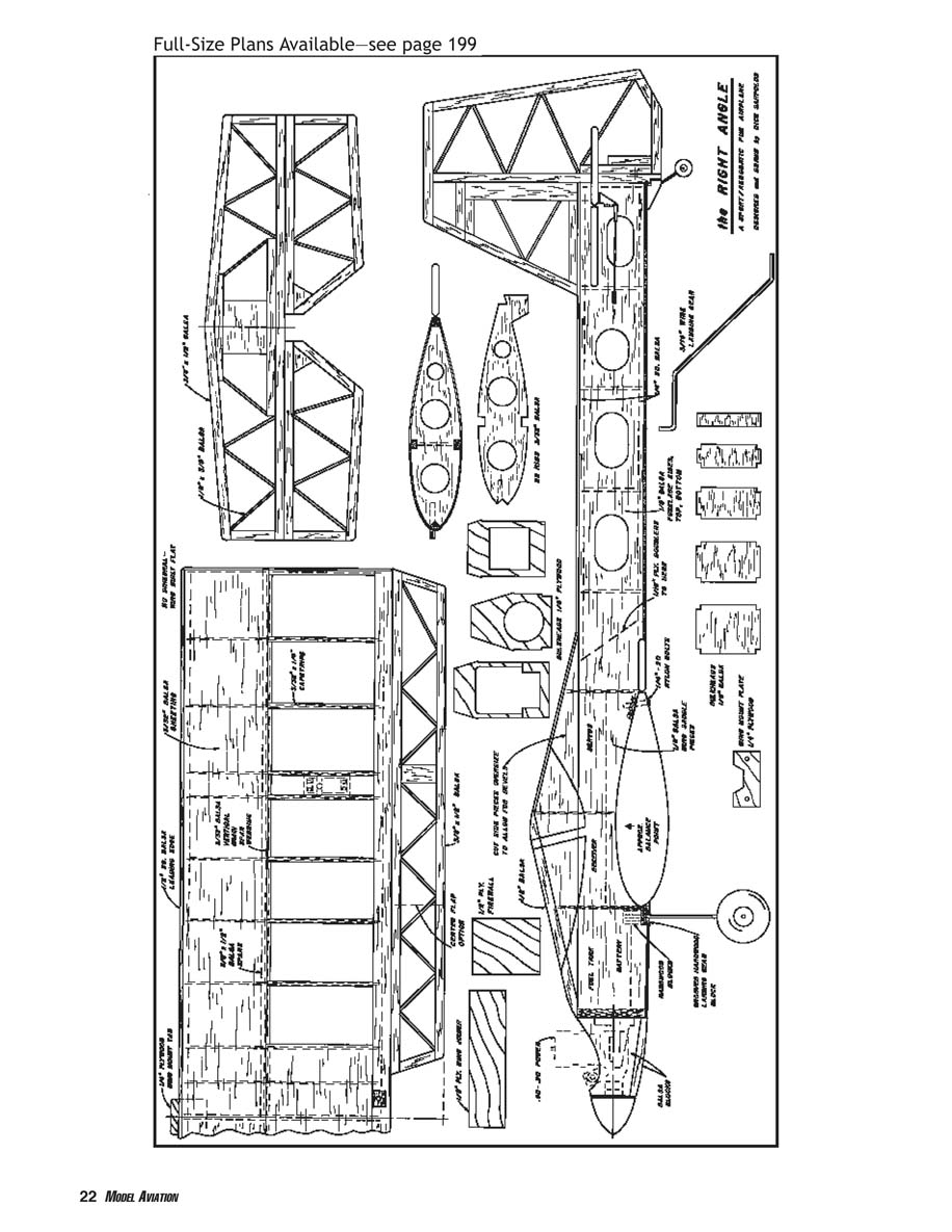
With the preceding in mind, I went to the drafting table and laid out the Right Angle. It’s an attempt to get a much lighter-than-“normal,” good-sized sport aerobatic aircraft while compromising to keep it easy to scratch-build and rugged enough for some less-than-gentle treatment.
The important statistics are the Right Angle’s 62-inch wingspan, 60-inch length, and roughly 900-square-inch wing area, which I thought would be lively with a SuperTigre .90 that I liked.
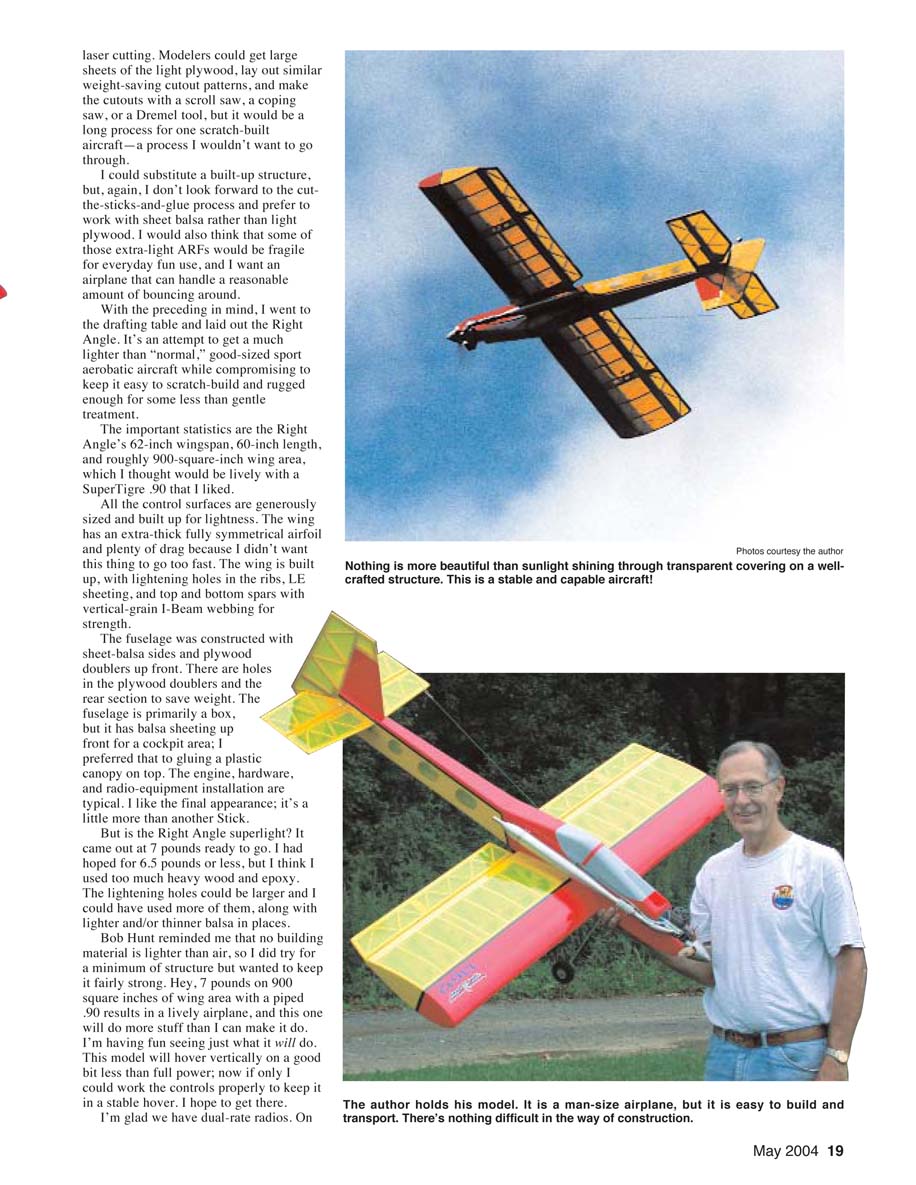
All the control surfaces are generously sized and built up for lightness. The wing has an extra-thick fully symmetrical airfoil and plenty of drag because I didn’t want this thing to go too fast. The wing is built up, with lightening holes in the ribs, leading-edge sheeting, and top and bottom spars with vertical-grain I-beam webbing for strength.
The fuselage was constructed with sheet-balsa sides and plywood doublers up front. There are holes in the plywood doublers and the rear section to save weight. The fuselage is primarily a box, but it has balsa sheeting up front for a cockpit area; I preferred that to gluing a plastic canopy on top. The engine, hardware, and radio-equipment installation are typical. I like the final appearance; it’s a little more than another stick.
But is the Right Angle superlight? It came out at 7 pounds ready to go. I had hoped for 6.5 pounds or less, but I think I used too much heavy wood and epoxy. The lightening holes could be larger and I could have used more of them, along with lighter and/or thinner balsa in places.
Bob Hunt reminded me that no building material is lighter than air, so I did try for a minimum of structure but wanted to keep it fairly strong. Hey, 7 pounds on 900 square inches of wing area with a piped .90 results in a lively airplane, and this one will do more stuff than I can make it do. I’m having fun seeing just what it will do. This model will hover vertically on a good bit less than full power; now if only I could work the controls properly to keep it in a stable hover. I hope to get there. I’m glad we have dual-rate radios. On high rate it can get scary, and on low rate I can actually feel comfortable flying it. This is not a contest airplane; it’s for casual fun-flying. It would probably be good with anything from a .60 up to a 1.20, as long as you don’t stress it too much with a larger engine.
If you are a dedicated scratch builder and want a Right Angle, you’ll probably just grab the plans and some wood and start cutting parts; it won’t take long. I don’t recommend it for a first attempt at scratch building. But then again, if you want to give it a try, why not?
If you’re not into scratch building but would still like to try the Right Angle, Joe Grasso is a good custom kit cutter. You can contact him at 8 Quiet Forest, Sylva NC 28779; Tel: (828) 631-3693; E-mail: [email protected].
You will need a scroll saw or a band saw to cut the parts to make your own kit. I used a hole saw in a drill press to cut the lightening holes in the wing ribs and plywood fuselage doublers. A hole saw doesn’t work too well in balsa; it made ragged cuts for me. I’ve been told that sharpening the end of a thin-walled brass tube makes a good hole cutter for balsa. I drew the fuselage-side lightening holes onto the wood, cut them out roughly with a modeling knife, and then finished them with a Dremel drum sander.
Specifications:
- Type: RC sport aerobatic
- Wingspan: 62 inches
- Length: 60 inches
- Wing area: roughly 900 square inches
- Engine: SuperTigre .90 with Mac's Products muffled tuned pipe
- Flying weight: 7 pounds
- Construction: Balsa and plywood
- Covering/finish: MonoKote
CONSTRUCTION
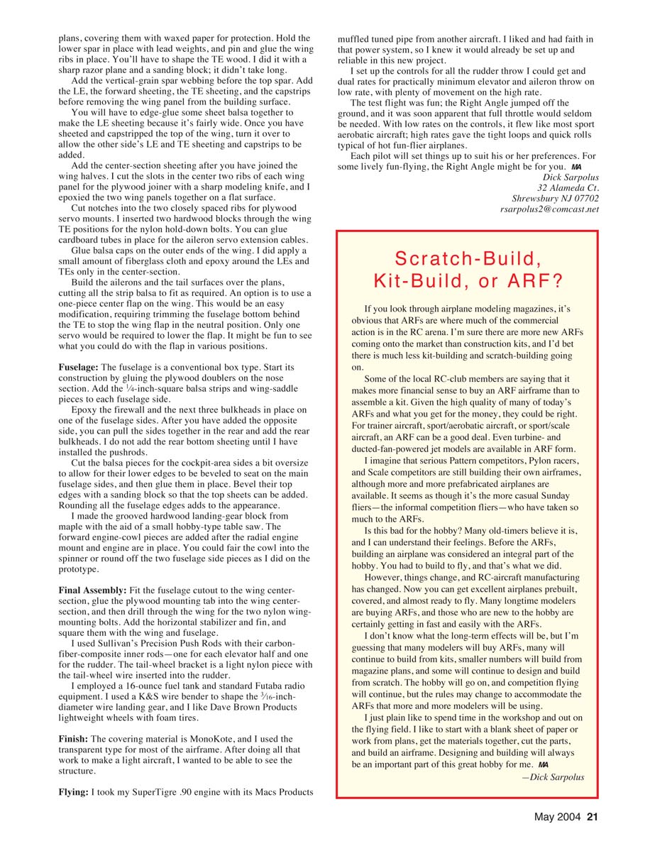
Wing
Start construction with the wing. I build directly over the plans, covering them with waxed paper for protection. Hold the lower spar in place with lead weights, and pin and glue the wing ribs in place. You'll have to shape the trailing-edge wood. I did it with a sharp razor plane and a sanding block; it didn't take long.
Add the vertical-grain spar webbing before the top spar. Add the leading edge (LE), the forward sheeting, the trailing-edge (TE) sheeting, and the capstrips before removing the wing panel from the building surface.
You will have to edge-glue some sheet balsa together to make the LE sheeting because it's fairly wide. Once you have sheeted and capstripped the top of the wing, turn it over to allow the other side's LE and TE sheeting and capstrips to be added.
Add the center-section sheeting after you have joined the wing halves. I cut the slots in the center two ribs of each wing panel for the plywood joiner with a sharp modeling knife, and I epoxied the two wing panels together on a flat surface.
Cut notches into the two closely spaced ribs for plywood servo mounts. I inserted two hardwood blocks through the wing TE positions for the nylon hold-down bolts. You can glue cardboard tubes in place for the aileron servo extension cables.
Glue balsa caps on the outer ends of the wing. I did apply a small amount of fiberglass cloth and epoxy around the LEs and TEs only in the center-section.
Build the ailerons and the tail surfaces over the plans, cutting all the strip balsa to fit as required. An option is to use a one-piece center flap on the wing. This would be an easy modification, requiring trimming the fuselage bottom behind the TE to stop the wing flap in the neutral position. Only one servo would be required to lower the flap. It might be fun to see what you could do with the flap in various positions.
Fuselage
The fuselage is a conventional box type. Start its construction by gluing the plywood doublers on the nose section. Add the 1/4-inch-square balsa strips and wing-saddle pieces to each fuselage side.
Epoxy the firewall and the next three bulkheads in place on one of the fuselage sides. After you have added the opposite side, you can pull the sides together in the rear and add the rear bulkheads. I do not add the rear bottom sheeting until I have installed the pushrods.
Cut the balsa pieces for the cockpit-area sides a bit oversize to allow for their lower edges to be beveled to seat on the main fuselage sides, and then glue them in place. Bevel their top edges with a sanding block so that the top sheets can be added. Rounding all the fuselage edges adds to the appearance.
I made the grooved hardwood landing-gear block from maple with the aid of a small hobby-type table saw. The forward engine-cowl pieces are added after the radial engine mount and engine are in place. You could fair the cowl into the spinner or round off the two fuselage side pieces as I did on the prototype.
Final Assembly
Fit the fuselage cutout to the wing center-section, glue the plywood mounting tab into the wing center-section, and then drill through the wing for the two nylon wing-mounting bolts. Add the horizontal stabilizer and fin, and square them with the wing and fuselage.
I used Sullivan's Precision Push Rods with their carbon-fiber-composite inner rods — one for each elevator half and one for the rudder. The tail-wheel bracket is a light nylon piece with the tail-wheel wire inserted into the rudder.
I employed a 16-ounce fuel tank and standard Futaba radio equipment. I used a K&S wire bender to shape the 3/16-inch-diameter wire landing gear, and I like Dave Brown Products lightweight wheels with foam tires.
Finish
The covering material is MonoKote, and I used the transparent type for most of the airframe. After doing all that work to make a light aircraft, I wanted to be able to see the structure.
Flying
I took my SuperTigre .90 engine with its Mac's Products muffled tuned pipe from another aircraft. I liked and had faith in that power system, so I knew it would already be set up and reliable in this new project.
I set up the controls for all the rudder throw I could get and dual rates for practically minimum elevator and aileron throw on low rate, with plenty of movement on the high rate.
The test flight was fun; the Right Angle jumped off the ground, and it was soon apparent that full throttle would seldom be needed. With low rates on the controls, it flew like most sport aerobatic aircraft; high rates gave the tight loops and quick rolls typical of hot-fun-flyer airplanes.
Each pilot will set things up to suit his or her preferences. For some lively fun-flying, the Right Angle might be for you.
Contact:
- Dick Sarpolus
- 32 Alameda Ct., Shrewsbury, NJ 07702
- [email protected]
Full-Size Plans Available — see page 199
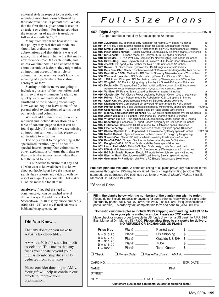
Plans/order listing:
- 957 Right Angle ........................................ $15.00
RC sport aerobatic model by Sarpolus, spans 62 inches
Transcribed from original scans by AI. Minor OCR errors may remain.

