
Ring Wing
by Ken Johnson
If you are the type of free-flight modeler who enjoys trying something unique, this model may be just the thing for you. Anyone can build a Piper Cub that flies; show me someone who can make a flying wing or a canard fly, and I'll show you a real modeler. The challenge of a radical planform is intriguing.
I started experimenting with air-powered models some years back, using the Air Hogs compressed-air motor unit marketed by Spin Master Toys. This little power plant puts out a great deal of torque and has a fair running time. My first air-powered model was a standard free-flight tractor style. It flew quite well and got me hooked on air power: it’s clean and inexpensive (roughly $15 for the motor), and the fuel is free. An airplane that weighs approximately 100 grams total is ideal; the span would be about 30–40 inches.
Since then I’ve built a variety of designs, including a joined-wing Diamond Gem, a Dragon Fly, a Butterfly, a scale-type flying wing, and a Sea Gull. My latest design uses the joined-wing concept with an oval shape: the Ring Wing.
My first Ring Wing flew well but was built too light and was prone to warping. The stabilizer began to distort after several weeks, changing its angle of attack and eventually rendering the model unflyable. I rebuilt it stronger: the first one weighed 88 grams, the new one 110 grams. I redrew the plans on a computer for better accuracy, enlarged them to a 35-inch wingspan, and used a pinstitch method to transfer outlines to the wood.
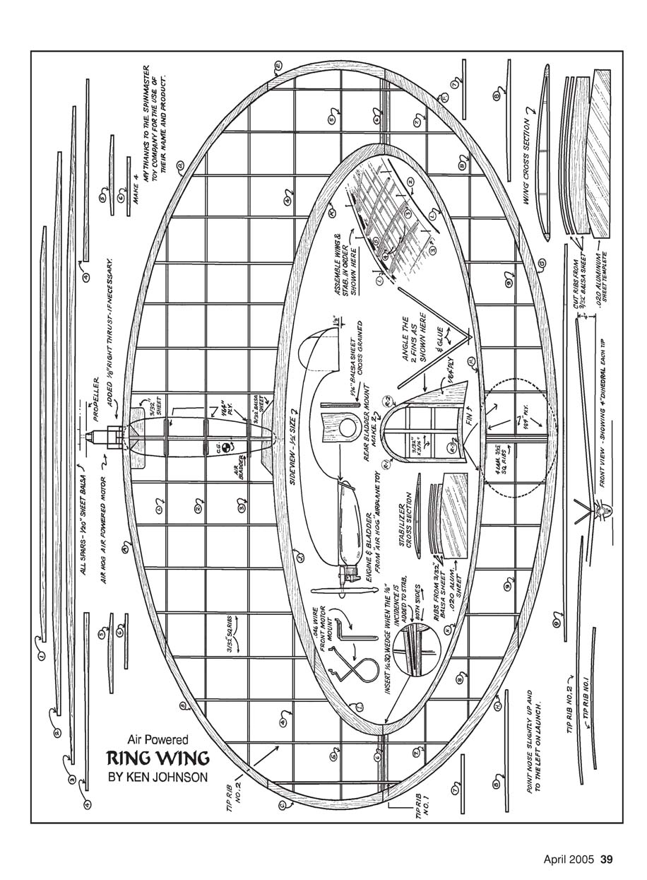
Since the tail of the second model is slightly larger (and a bit tail-heavy), it requires a small amount of ballast at the nose. The Ring Wing climbs to the left and reaches about 100–150 feet before transitioning to the glide. It requires roughly 1/8 inch of right thrust to open up the left turn. This design has not flown in thermal air yet, but it should perform well.
Construction
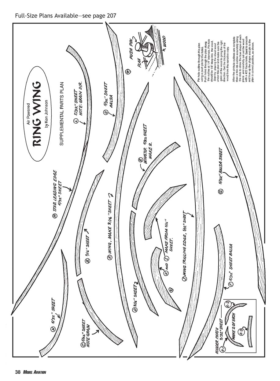
See the plans for the wing and stabilizer outlines before starting. The following steps summarize the build.
- Materials and preparation
- Wing leading edge (LE): 3/16-inch sheet, quarter-grain balsa. Position the wood with the grain running lengthwise under the proper plan outline.
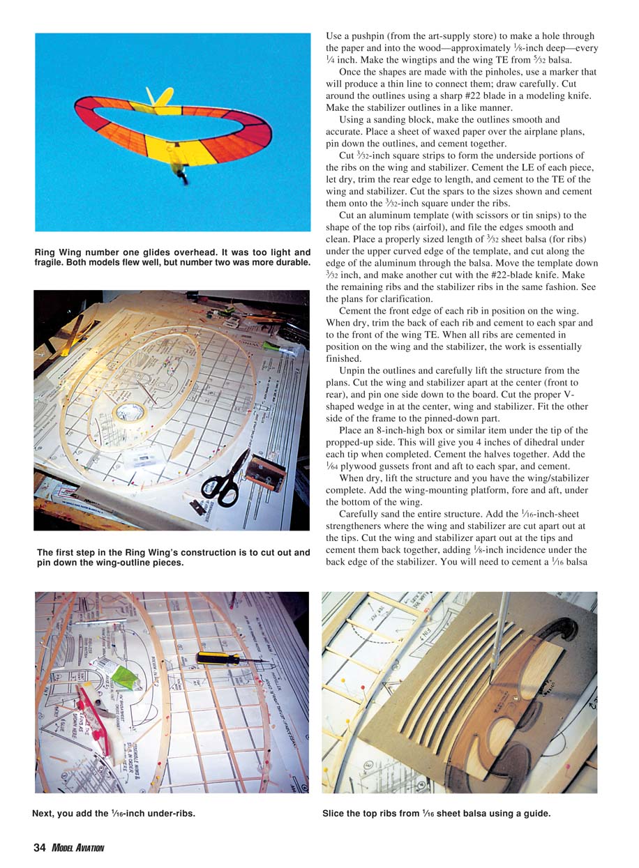
- Top ribs: slice from 1/16-inch sheet balsa using a guide.
- Wingtips and wing trailing edge (TE): 5/32-inch balsa.
- Underside rib stock: 3/32-inch square strips.
- Spars and gussets as shown on the plans.
- Use a sheet of waxed paper over the plans to prevent gluing to the board.
- Transfer the outlines
- Pin down the paper plan. Using a pushpin, make a hole through the paper and into the wood about 1/8 inch deep every 1/4 inch along the outline.
- Connect the pinholes with a thin-line marker and cut around the outline with a sharp #22 blade.
- Sand outlines smooth and accurate with a block.
- Assemble basic wing and stabilizer frames
- Cement the leading edge pieces in position and let dry.
- Trim the rear edge to length and cement to the TE pieces.
- Cut and cement the spars to size as shown on the plans.
- Cut 3/32-inch square strips for the underside portions of the ribs for both wing and stabilizer; cement in place.
- Make and fit the top ribs (airfoil)
- Cut an aluminum template to the top-rib shape and file edges smooth.
- Place a properly sized length of 3/32-inch sheet balsa under the template’s curved edge and cut along the aluminum with a #22 blade.
- Move the template down 3/32 inch and make another cut for the rib thickness. Repeat to make the remaining ribs and stabilizer ribs.
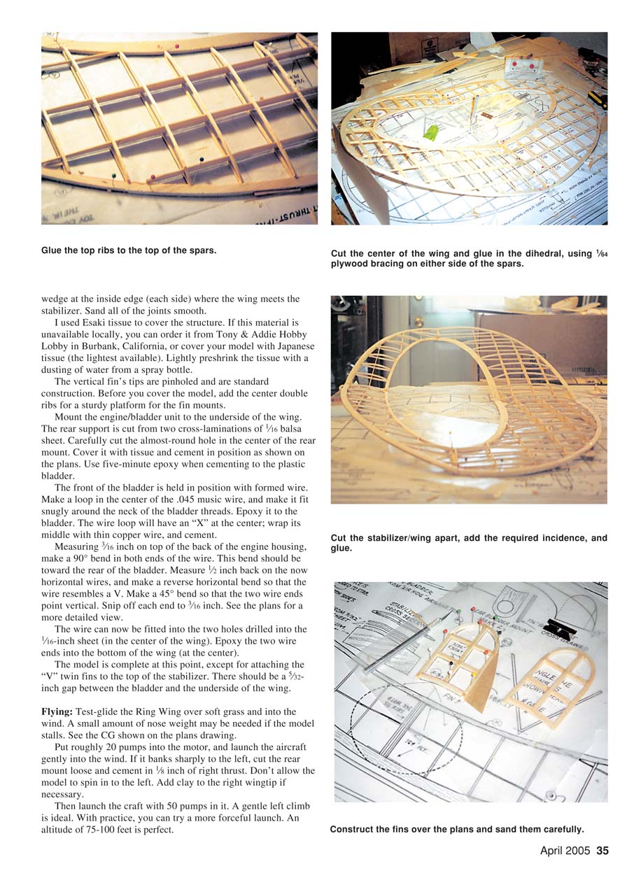
- Cement the front edge of each top rib to the wing/semi-structure. When dry, trim the rear of each rib and cement them to each spar and to the front of the TE.
- Joining halves and dihedral
- Unpin the outlines and carefully lift the structure from the plans.
- Cut the wing and stabilizer apart at the center (front to rear). Pin one side down.
- Cut the proper V-shaped wedge at the center on both wing and stabilizer and fit the other side.
- Prop the raised tip side on an 8-inch-high box (this yields about 4 inches of dihedral under each tip when completed) and cement the halves together.
- Add 1/64-inch plywood gussets front and aft to each spar and cement.
- Final structure work
- Add wing-mounting platforms fore and aft under the bottom of the wing.
- Add 1/16-inch-sheet strengtheners where the wing and stabilizer were cut near the tips.
- Cut the wing and stabilizer apart near the tips and cement them back together, introducing 1/8-inch incidence under the rear edge of the stabilizer. Cement a 1/16-inch balsa wedge at the inside edge (each side) where wing meets stabilizer.
- Sand all joints smooth.
- Covering
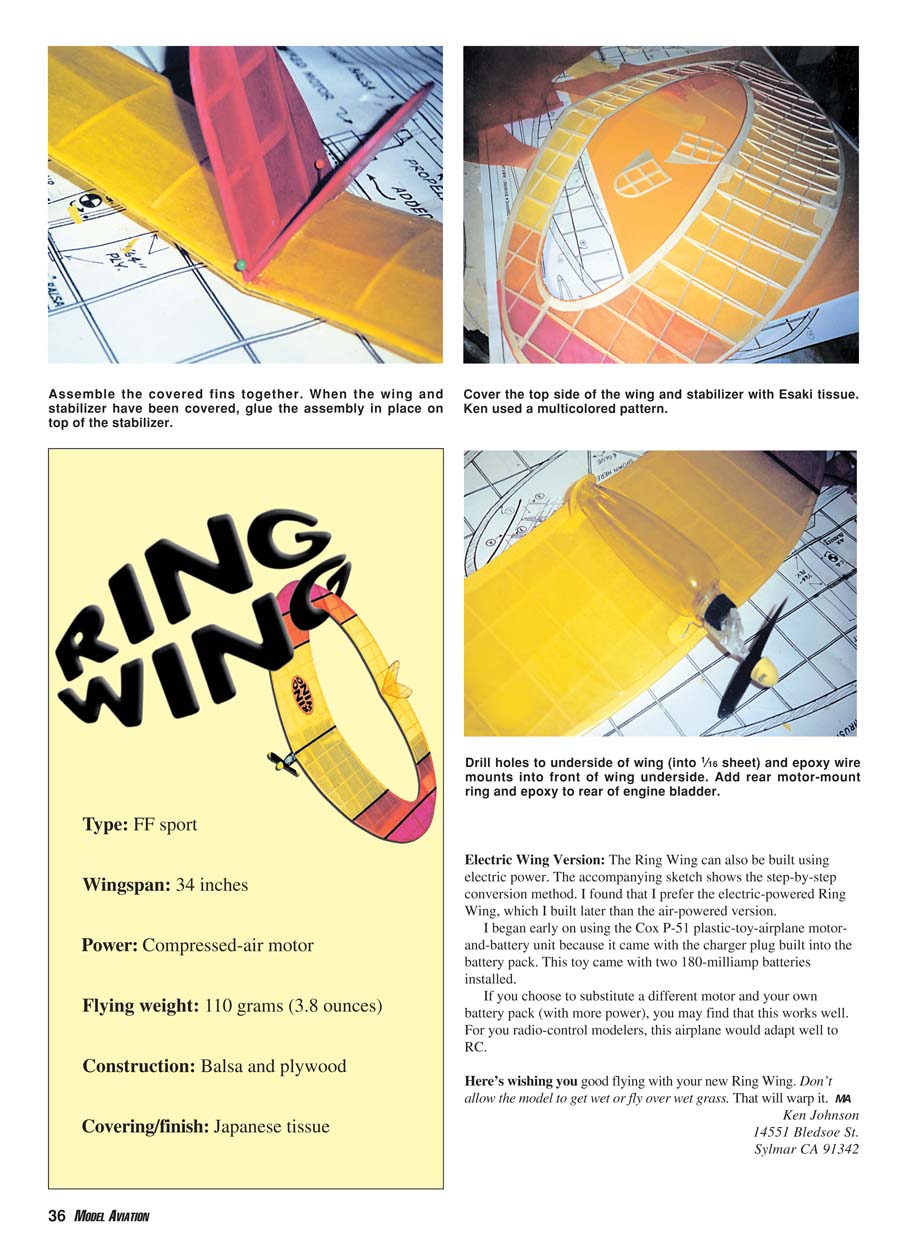
- I used Esaki tissue to cover the structure. If unavailable, use the lightest Japanese tissue you can find.
- Lightly preshrink the tissue with a dusting of water from a spray bottle.
- Before covering, add the center double ribs to provide a sturdy platform for the fin mounts.
- Vertical fins and final fit
- The vertical fin tips are pinholed and of standard construction; add them to the top of the stabilizer, leaving a suitable gap where shown on the plans.
- There should be a 3/32-inch gap between the bladder and the underside of the wing.
- Mounting the engine/bladder unit
- Mount the engine/bladder to the underside of the wing. The rear support is cut from two cross-laminations of 1/16-inch balsa sheet.
- Carefully cut the nearly-round hole in the center of the rear mount, cover it with tissue, and cement in position as shown on the plans.
- Use five-minute epoxy when cementing to the plastic bladder.
- Bladder front hold-down (wire)
- Form a loop in the center of 0.045-inch music wire and fit it snugly around the neck of the bladder threads. Epoxy it to the bladder.
- The loop will have an “X” at the center; wrap its middle with thin copper wire and cement.
- Measure 3/16 inch up from the back of the engine housing and make a 90° bend in both wire ends toward the rear.
- Measure 1/2 inch back on the now-horizontal wires and make a reverse bend so the wire resembles a V. Make a 45° bend so the two wire ends point vertical, and snip each end to 7/16 inch. See the plans for details.
- Fit the wire into two holes drilled into a 1/16-inch sheet in the wing center and epoxy the wire ends into the bottom of the wing.
- Finish sanding and final assembly
- When dry, lift the structure and you have the wing/stabilizer complete. Sand the entire structure carefully.
- Mount the vertical (V) twin fins to the top of the stabilizer.
- The completed model is essentially ready to fly.
Covering note and supplies: If Esaki tissue is not available locally, you can order it from Tony & Addie Hobby Lobby in Burbank, California, or use light Japanese tissue.
Flying
- Test-glide the Ring Wing over soft grass and into the wind.
- A small amount of nose weight may be needed if the model stalls. Refer to the CG shown on the plans.
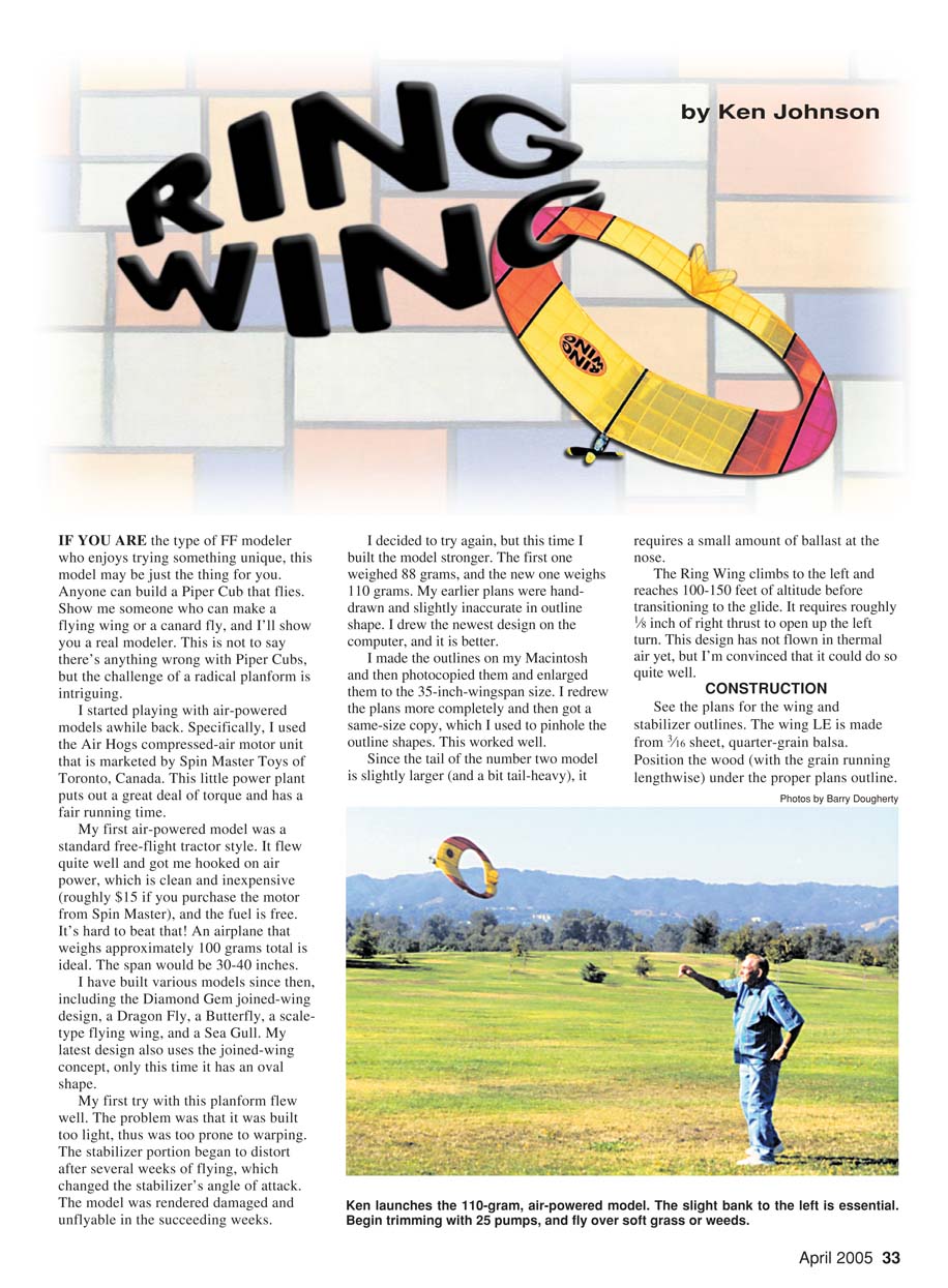
- Put roughly 20 pumps into the motor and launch gently into the wind.
- If it banks sharply to the left, cut the rear mount loose and cement in 1/8 inch of right thrust. Do not allow the model to spin into the left; add clay to the right wingtip if necessary.
- With more pumps (about 50), a gentle left climb is ideal. With practice you can try a stronger launch; an altitude of 75–100 feet is perfect.
- Avoid flying over wet grass or allowing the model to get wet — moisture will warp it.
Specifications
- Type: Free-flight sport
- Wingspan: 34 inches
- Power: Compressed-air motor
- Flying weight: 110 grams (3.8 ounces)
- Construction: Balsa and plywood
- Covering/finish: Japanese or Esaki tissue
Electric Wing Version
The Ring Wing can also be built using electric power. I prefer the electric version and built one after the air-powered model. The conversion is straightforward and adapts well to radio control if desired.
- Early electric conversion: I used the Cox P-51 toy motor-and-battery unit because its charger plug is built into the battery pack; it used two 180 mAh NiCd cells.
- You may substitute a different motor and battery pack for more power. For R/C adaptation, choose a small motor and battery appropriate to weight and desired performance.
Electric build notes (from plan sketch)
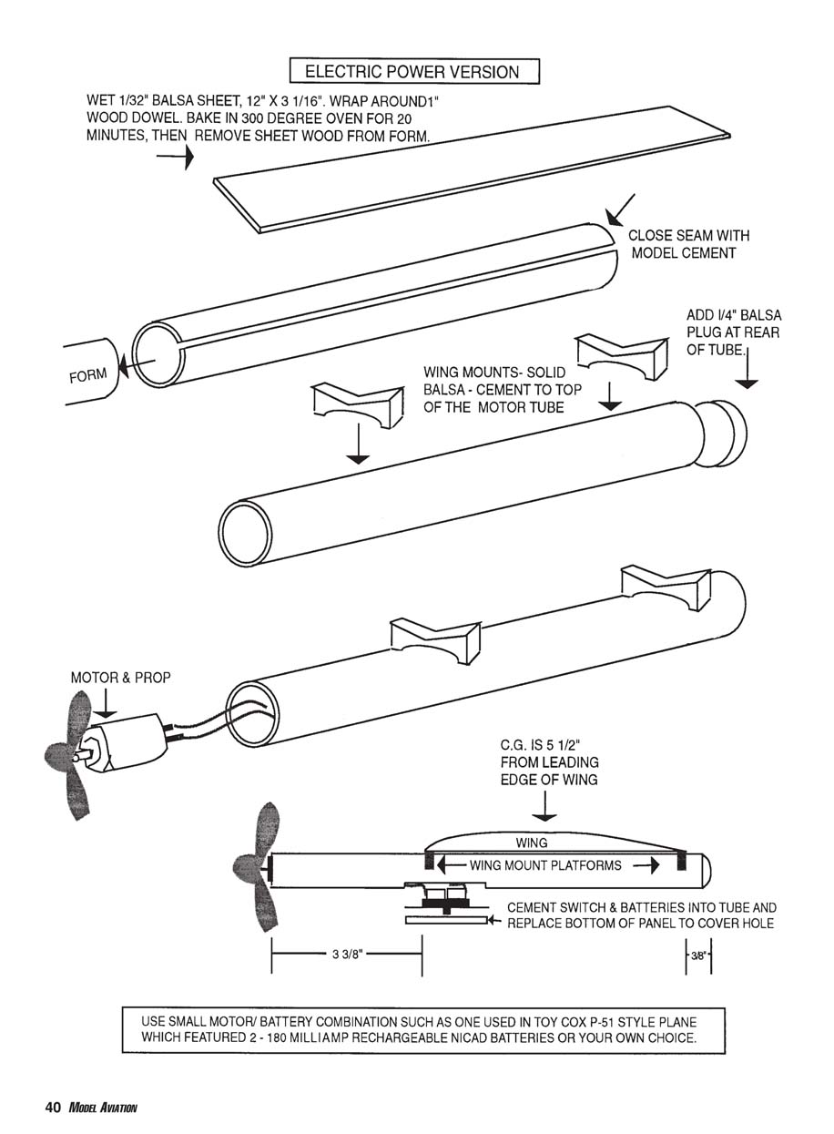
- Wet a 1/32-inch balsa sheet (12-inch x 3 1/16-inch), wrap it around a 1-inch wood dowel, bake in a 300°F oven for 20 minutes, then remove the formed wood from the form.
- Close the seam with model cement and add a 1/4-inch balsa plug at the rear of the tube.
- Wing mounts: solid balsa, cement to the top of the motor tube.
- Motor and prop: use a small motor/battery combination such as the Cox P-51-style toy unit (two 180 mAh NiCd cells) or your own choice.
- Center of gravity (C.G.) is 5 1/2 inches from the leading edge of the wing (confirm on your built model).
- Cement switch and batteries into the tube and replace the bottom panel to cover the hole.
Dimensions called out on the sketch (refer to plans for exact placement):
- 3 3/8 inches (feature on sketch)
- 3/8 inch (feature on sketch)
Modifying the Stock Air Hogs Pump
You will likely want to alter the Air Hogs pump so you can use it with larger models, such as the Ring Wing. The stock setup straps the toy airplane close to the pump handle, which risks hitting the tail during pumping.
I tried several solutions:
- A pump with a 4-inch plastic tube worked but failed after a while.
- A Wind Jammer pump with a 14-inch tube worked well but is hard to obtain.
- A modified tire pump is usable but awkward to operate single-handed.
- A newer connector style from Estes is incompatible with the Ring Wing.
My modification:
- Fit a 10-inch length of 1/4-inch outside-diameter (OD) clear plastic tubing over the existing pump nozzle.
- Lock the tubing down by twisting a small paper-clip (.028-inch) around the tubing and pump nozzle with pliers, then trim off the excess.
- Insert a 1-3/4-inch length of 3/16-inch OD aluminum tubing into the open end of the plastic tube.
- Use the paper-clip clamp over the plastic and aluminum to secure them.
- Flute the other end of the aluminum tubing slightly so it presses snugly into the filler nozzle on the motor.
The result lets you hold the Ring Wing in one hand while pumping with the other, keeping the airplane well away from the pump handle. If the model’s nozzle expands from repeated use, ream out the aluminum nozzle slightly to maintain a snug fit.
I hope this helps you get many outstanding flights with the Ring Wing.
— Ken Johnson 14551 Bledsoe St. Sylmar, CA 91342
Transcribed from original scans by AI. Minor OCR errors may remain.

