
Roll Out
Bob Dunham
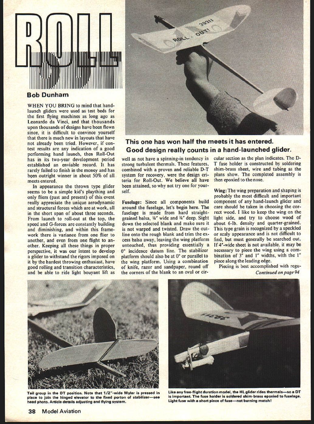
When you bring to mind that hand-launch gliders were used as test beds for the first flying machines as long ago as Leonardo da Vinci, and that thousands upon thousands of designs have been flown since, it is difficult to convince yourself that there is much new in layouts that have not already been tried. However, if contest results are any indication of a good performing hand-launch, then Roll-Out has in its two-year development period established an enviable record. It has rarely failed to finish in the money and has been outright winner in about 50% of all meets entered.
In appearance the thrown type glider seems to be a simple kid's plaything and only fliers (past and present) of this event really appreciate the unique aerodynamic and structural forces which are at work, all in the short span of about three seconds. From launch to roll-out at the top, the speed and G-forces are constantly building and diminishing, and within this framework there is variance from one flier to another, and even from one flight to another. Keeping all these things in proper perspective, it was our intent to develop a glider to withstand the rigors imposed on it by the hardest throwing enthusiast, have good rolling and transition characteristics, and be able to ride light buoyant lift as well as not have a spinning-in tendency in strong turbulent thermals. These features, combined with a proven and reliable D-T system for recovery, were the design criteria for Roll-Out. We believe all have been attained, so why not try one for yourself.
Fuselage
Since all components build around the fuselage, let's begin here. The fuselage is made from hard straight-grained balsa, 1/4" wide and 3/16" deep. Sight down the selected blank and make sure it is not warped and twisted. Draw the outline onto the rough blank and trim the excess balsa away, leaving the wing platform untouched, thus providing essentially a 0° incidence datum line. The stabilizer platform should also be at 0° or parallel to the wing platform. Using a combination of knife, razor and sandpaper, round off the corners of the blank to an oval or circular section as the plan indicates. The D-T fuse holder is constructed by soldering shim-brass sheet, wire and tubing as the plans show. The completed assembly is then epoxied to the nose.
Wing
The wing preparation and shaping is probably the most difficult and important component of any hand-launch glider and care should be taken in choosing the correct wood. I like to keep the wing on the light side, and try to choose wood of about 6-lb. density and quarter-grained. This type grain is recognized by a speckled or scaly appearance and is not difficult to find, but must generally be searched out. If 4"-wide sheet is not available, it may be necessary to piece the wing using a combination of 3" and 1" widths, with the 1" piece along the leading edge. Piecing is best accomplished with regu-
Roll Out/Dunham continued from page 38
regular model cement because it sands and works easier than epoxy or white glues. The seam should be a tight fit and allowed to dry thoroughly before proceeding. Trace the wing outline and airfoil high-point line with a ball-point pen and cut almost to outline, leaving 1/16" all around for final finish. The first important step is to carefully sand in about 1/32" tip washout on the bottom side in the area shown on the plan. This is a delicate operation and only a little is required, so don't overdo.
I use a small razor plane to shape the rear airfoil portion of the blank from the high point line to the trailing edge, keeping it as flat as possible, and use a straightedge for a check. Sand out all the hills and valleys using a sanding block, but maintain a trailing edge thickness of about 1/32". The leading edge is next, and it should have a bit of top camber, leaving enough thickness at the front for the bottom side curved entry and leading edge radius. The outer wing tip panels should be tapered and thinned, keeping the airfoil shape all the way. Next, trim to exact outline and final sand using progressively finer grit down to 400 W-D.
The wing next is cut into four pieces at the dihedral points and the ends carefully beveled to make the correct angles and are epoxied. These joints should be a good tight fit with no gaps or else disaster is waiting in the wings (double entendre). Allow to cure thoroughly and build up a glue skin at each break to help strengthen the joints. The fuselage is then V-notched to accept the mid-dihedral point and the wing is centered and glued in place. A glue fillet on the under side along the fuselage is desirable. The forefinger reinforcement triangle is cut and edges streamlined, then glued to the underside of the wing. Conform the finger oval to a snug fit using sandpaper wrapped around a dowel or pencil.
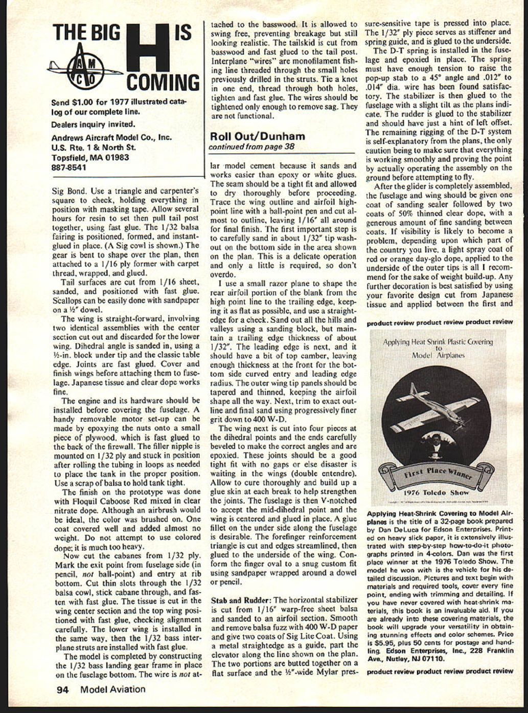
Stab and Rudder: The horizontal stabilizer is cut from 1/16" warp-free sheet balsa and sanded to an airfoil section. Smooth and remove balsa fuzz with 400 W-D paper and give two coats of Sig Lite Coat. Using a metal straightedge as a guide, part the elevator along the line shown on the plan. The two portions are butted together on a flat surface and the 1/2"-wide Mylar pressure-sensitive tape is pressed into place. The 1/32" ply piece serves as stiffener and spring guide, and is glued to the underside.
The D-T spring is installed in the fuselage and epoxied in place. The spring must have enough tension to raise the pop-up stab to a 45° angle and .012" to .014" dia. wire has been found satisfactory. The stabilizer is then glued to the fuselage with a slight tilt as the plans indicate. The rudder is glued to the stabilizer and should have just a hint of left offset. The remaining rigging of the D-T system is self-explanatory from the plans, the only caution being to make sure that everything is working smoothly and proving the point by actually operating the assembly on the ground before attempting to fly.
After the glider is completely assembled, the fuselage and wing should be given one coat of sanding sealer followed by two coats of 50% thinned clear dope, with a generous amount of fine sanding between coats. If visibility is likely to become a problem, depending upon which part of the country you live, a light spray coat of red or orange day-glo dope, applied to the underside of the outer tips is all I recommend for the sake of weight build-up. Any further decoration is best satisfied by using your favorite design cut from Japanese tissue and applied between the first and second coats.
Flying:
Your glider will probably need a small amount of weight on the nose to make the ship balance at the 50% point of the wing chord. If you are right-handed, the glide circle should be definitely to the left. To rough trim, pick a calm day and a field with foot-high soft grass, and proceed to launch with a left bank inclination, and with enough force to gain about 30 feet of height. The ship should go over the top and into its 40-ft. diameter glide circle with little or no dip and descend without diving or stalling. Compensating adjustments should be made to the stabilizer by shimming, 1/64" at a time.
Next, slip a fuse in the nose tube and light it, using another piece of burning fuse. Never use a burning match for lighting, or you may end up with the whole nose section afire. After taking a few steps into the wind, launch the ship with the nose up at about a 60° angle and banked to the right. The glider should climb in a right pattern and as it slows should go over the top into a left-hand glide. A hard throw is necessary to realize the full potential, and a half-hard launch could be disastrous if enough speed is not attained to take the ship through the top transition portion. Only repeated trial and not too many errors will give you the experience to know.
Remember, no hand launch will do the two-minute max without thermal help, but a well adjusted and thrown Roll-Out will get you about halfway there in neutral air. So if you want to win contests, you must look for the tell-tale signs of lift before making your official calls. The dethermalizer permits test flights to be made and to determine what these signs are for that particular day as well as to limber up and just fly for the fun of it, without risk of losing the ship.
Transcribed from original scans by AI. Minor OCR errors may remain.

