
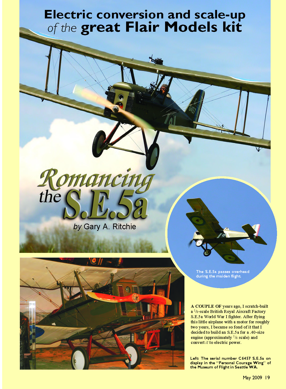

Romancing the S.E.5a
Electric conversion and scale-up of the great Flair Models kit
by Gary A. Ritchie
A couple of years ago I scratch-built a 1/8-scale British Royal Aircraft Factory S.E.5a World War I fighter. After flying this little airplane with a motor for roughly two years, I became so fond of it that I decided to build an S.E.5a for a .40-size engine (approximately 1/6 scale) and convert it to electric power.
For this project I selected the version that Flair Models produces in the United Kingdom (and Radical RC markets in the US). This is a kit—not an ARF.
A significant modeling advantage that the S.E.5a has over many WW I fighters is its relatively long nose. This provides ample room for a motor and a battery pack. Other attractive WW I biplanes, such as the Sopwith, Spad, and Nieuport, have short noses, making them difficult to balance on the CG without adding lots of nose weight. I don’t like to add weight unnecessarily.
I enjoy converting a simple kit-built airplane to a realistic, scalelike model. This includes adding many details: authentic color-and-markings, weapons, cockpit, pilot, wing wires, realistic landing gear, open cockpits, and exposed engine details. Below I’ll take you through some of the issues I confronted while converting the Flair Models S.E.5a to a scale-looking, electric-powered model.
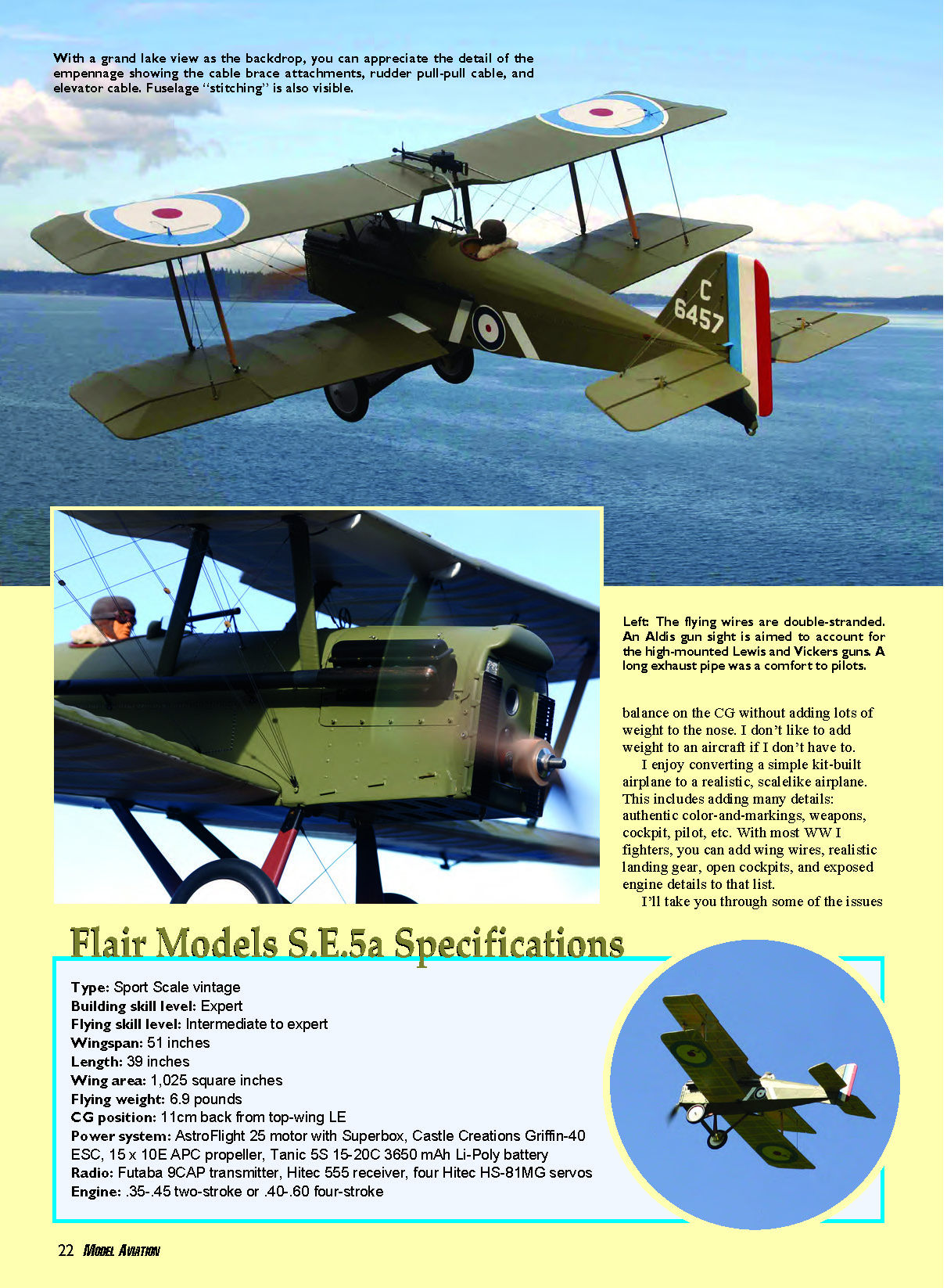
Flair Models S.E.5a Specifications
- Type: Sport-scale vintage
- Building skill level: Expert
- Flying skill level: Intermediate to expert
- Wingspan: 51 inches
- Length: 39 inches
- Wing area: 1,025 square inches
- Flying weight: 6.9 pounds
- CG position: 11 cm back from top-wing leading edge
- Power system: AstroFlight 25 motor with Superbox, Castle Creations Griffin-40 ESC, 15 x 10E APC propeller, Tanic 5S 15–20C 3650 mAh Li-Poly battery
- Radio: Futaba 9CAP transmitter, Hitec 555 receiver, four Hitec HS-81MG servos
- Engine (kit provision): .35–.45 two-stroke or .40–.60 four-stroke
To build a scale model you must decide what full-scale subject you want and then develop a documentation package for that airplane. I selected a beautiful S.E.5a replica (serial number C6457) that is located in the "Personal Courage Wing" of the Museum of Flight in Seattle, Washington.
I wanted to replicate this airplane as closely as I could. A good friend and fellow modeler who is a docent at the museum provided me with an opportunity to take many close-up photographs of the S.E.5a as the basis for my documentation.
The Flair Models S.E.5a is your basic, old-fashioned, die-cut balsa-and-plywood kit—nothing fancy. It contains strip and sheet wood, precut wing ribs and formers, glow engine-mounting hardware, a hardware pack, plans, and instructions.
The plans are excellent; the instructions would benefit from illustrations and a few more details. The die-cutting was generally good, but I had to do some razor-blade work on several of the plywood parts. The wood quality was fair.
Electric Power-System Design
The full-scale S.E.5a's top speed with the Wolseley Viper V8 engine was 138 mph. This translates to a 1/6-scale top speed in the neighborhood of only 23 mph. I was not interested in a hopped-up motor configuration to deliver high power loadings; I wanted only to replicate scale speed as closely as possible.
I estimated that a power system generating roughly 70–80 watts per pound would give scalelike flight for this high-drag airplane. I estimated the model's all-up weight, including a Li-Poly battery pack, to be 6.5–7.0 pounds. A scale propeller would be approximately 16 inches long. I had a surplus AstroFlight 25 motor with a 3.1:1 geared Superbox that I wanted to use.
From experience I estimated I would need 18–20 volts from the battery pack. Using ElectriCalc, simulations with a 16 x 10 APC electric propeller indicated a draw of about 44 amps and close to 81 watts per pound of model. Dropping to a 15 x 10 propeller reduced current draw to roughly 40 amps and power to about 75 watts per pound. I decided to go with the 15 x 10, knowing I could change props later if needed.
Detailing the S.E.5a
Both wings and the tail feathers went together easily. The ribs cut from plywood were quite strong. I used a square to align all parts as I built them over the plans using pins.
I used a glue that was new to me and that I highly recommend: Titebond Molding and Trim Wood Glue. It is an aliphatic glue but is thicker than traditional carpenter's glue and sets up rapidly. The hardware store had to special-order it for me.
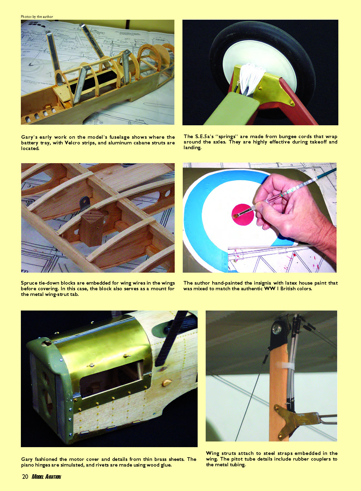
Rather than using the nylon control horns provided in the kit, I made scalelike control horns from 1/16-inch circuit-board material. I glued several predrilled spruce blocks into the wings to serve as strong fastening points for the wing wires.
I used cyanoacrylate hinges throughout, rather than the hinges included with the kit. I glued a 1/16-inch balsa strip on the upper center of the upper wing to later serve as a mounting plate for the Lewis machine gun. To improve scale appearance, I added a partial wing rib to the leading edge between each existing rib.
Rather than use one centrally mounted servo with pushrods and bellcranks for the ailerons, I installed a Hitec HS-81MG servo in each wing. Servo extensions ran through the wings, exiting at the center where they engaged the aileron Y connector.
The S.E.5a contains a maze of wires running among struts, the fuselage, cabanes, and tail sections. Just sorting them and identifying them was a challenge; I would not have been able to do it without the museum photos.
I began by sketching the wires on paper. Then, before covering the wings and fuselage, I embedded a 1/2-inch square hardwood block at each point where a wire was connected. Each block was predrilled with a 1/16-inch hole. Before painting the model, I poked a small hole in the covering at each attachment point to mark its location.
With the fuselage, a challenge was mounting the battery pack and motor. With a monoplane I would normally construct a removable hatch forward of the canopy to create a battery compartment. That was out of the question with this biplane because of the location of the cabane struts and support wires.
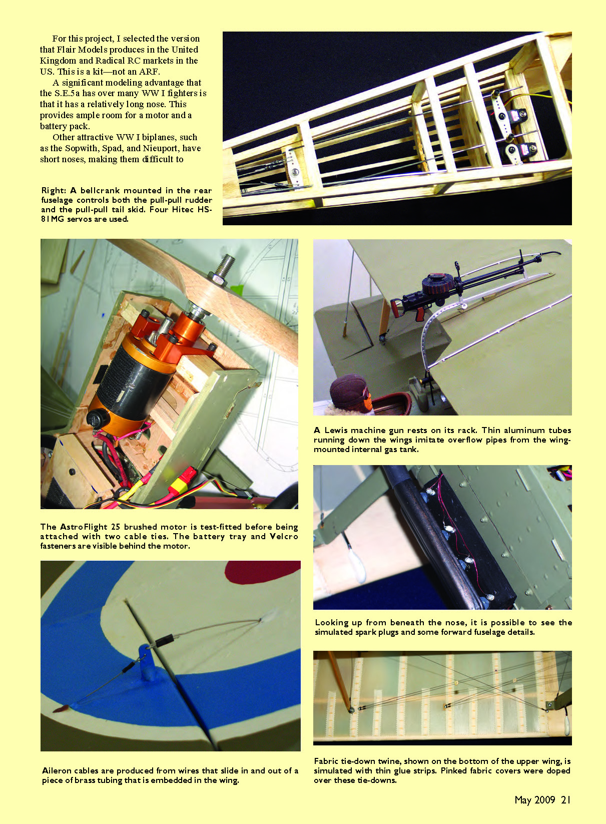
Therefore I made a removable nose that slides into the fuselage from the front and provides access to the motor and the battery tray. I mounted the motor with cable ties fastened around two metal bolts in the lower nose.
The full-scale S.E.5a's turtledeck has several shorter stringers just aft of the cockpit. I added these using basswood strips. I mounted the servos just aft of the cockpit and a Hitec Micro 555 receiver beneath it. A removable 1/16-inch plywood belly plate screws to the bottom of the fuselage to conceal these components.
The elevator is actuated with a metal rod that protrudes down into the rear of the fuselage from the elevator torsion bar to engage the pushrod. I installed fake cables on the elevator to simulate the cable arrangement.
The rudder works with a pull-pull cable system. The rudder servo turns a bellcrank inside the fuselage just forward of the rudder. To this bellcrank I attached two sets of pull-pull wires: one serving the rudder, the other serving the steerable tail skid.
Landing gear was constructed from 1/8-inch-diameter steel wire faired with 1/4-inch hard balsa. Springs were made from bungee cord wrapped around the axle and strut to give a spring effect upon landing. The 4-1/2-inch-diameter scale wheels are from Williams Brothers.
The full-scale S.E.5a's nose is mostly metal and wood, and the fuselage aft of the cockpit is fabric-covered stringers. Wings and tail surfaces are fabric covered.
On the model I made the nose portions of the fuselage from either #250 brass sheet or 1/16-inch balsa sheeting. I covered the balsa with GM (gas model)-grade Silkspan and coated it several times with nitrate dope to smooth the grain.
I covered the aft fuselage, wings, and empennage with Nelson Hobby Specialties' LiteFAB Natural iron-on fabric. As on the full-scale S.E.5a and many other WW I airplanes, the fabric was bound to the ribs using twine; the ribs were then covered with strips of pinked fabric.
The twine was simulated using lines of wood glue applied with a syringe fitted with a 1/8-inch-diameter brass tube in its nose; I also simulated the many fuselage rivets with this method. Each line ran across the rib cover, spaced 1/2 inch apart. I applied this technique to the top and bottom of both wings and tail surfaces. Then I overlaid the rib covers with 1/2-inch-wide pinked fabric strips, available from F&M Enterprises.
The entire model was sealed with several coats of non-tautening nitrate dope from Aerodyne. The full-scale S.E.5a was painted with a color known as PC-10, while the undersides of both wings and the elevator were doped fabric. PC-10 is a green drab color that airplane painters often mixed on-site; there is no single specific formula.
To simulate PC-10, I took some of my photos of the full-scale S.E.5a to a Benjamin Moore paint store to have the color matched. It turned out nearly perfect, and I had a quart of interior latex eggshell paint of the color made. I thinned it roughly 9:1 paint to water and applied three coats with a paintbrush, trying to replicate a rough, hand-painted surface. (They didn't use airbrushes in WW I.)
Wing markings were a challenge. I had ordered roundel decals from an Internet source but realized that I could not apply them because of the roughness of the fabric cover strips and ties. Fortunately I had not yet applied the PC-10 to the wings, so I drew the roundels on the doped fabric with a pencil and painted them by hand using thinned latex paint. I painted the wings after applying the roundels. On the underside of the bottom wings, I hand-painted the roundels over the doped fabric.
Final Touches
Someone once said that an S.E.5a viewed from the front looked like a farm tractor with wings. The Wolseley Viper V8's valve covers and exhaust manifolds protrude from the nose. Exhaust pipes connect to the manifold and extend aft to beneath the cockpit opening. I carved the pipes from balsa, added tiny brass bolts, and simulated spark plugs on the valve covers.
When the model was fully assembled, I attached the wing and tail wires using 0.014-inch fine braided beading wire from the Soft Flex Company. I connected the wires to the wood attachment blocks using spring clasp connecting tabs (item FI104-G) from Shipwreck Beads.
The clasps were screwed into the wooden blocks using #2 x 3/8-inch button-head screws. The wire ends were passed through the tabs and swaged together using 0.033-inch Mason Connector Sleeves from Thorn Brothers that I crimped with a crimping tool.
After adding a few final details—such as the wing-mounted Lewis machine gun and rack, a homemade pitot tube, Aldis gun sight, instrument panel, scale propeller, and windshield—the model was finished.
Static Testing
I performed a static test on the power system using an S3 3650 Li-Poly battery and a 15 x 8E APC propeller. At full throttle the system drew 30 amps and produced 600 watts with the propeller spinning at 4,590 rpm.
The S.E.5a's all-up weight was 6.94 pounds, so the power loading was 86 watts per pound. By moving the battery tray all the way forward, I achieved a CG that was right on the mark: 11 centimeters (4.3 inches) back from the upper wing's leading edge, without adding weight.
I set the control throws as follows: aileron 20 mm up and 10 mm down, elevator roughly 15 mm, and rudder approximately 20 mm. I used only low rates and dialed in close to 35% exponential on each control surface.
Flying
Uncertain of how the S.E.5a would perform, I waited for a warm, relatively calm spring day for the maiden flight. Our grass field is quite bumpy, but the model rolled over it at a good clip, hardly bouncing. I attribute this to the effective bungee springs on the landing gear.
The airplane lifted off easily and smoothly and, following a touch of downtrim, flew gracefully as I made shallow turns and slow passes around the field. I handed the transmitter to my flying buddy, Bob Benjamin, who brought it around for a few low passes while I clicked away with my Canon Rebel SLR camera.
On the first landing a touch of power at the end prevented the model from flipping over in the grass. The first flight revealed the airplane was a bit underpowered, so I replaced the 15 x 8 propeller with a 15 x 10, which helped somewhat.
As of this writing I have nearly 50 successful flights on my model. It performs extremely smoothly and with great authority—similar to a full-scale S.E.5a. Turns are more scalelike if initiated with the rudder and a touch of down-elevator. It is important that the CG is set properly; the airplane becomes a handful when it is even slightly tail-heavy.
Flair Again?
This project required almost three years to complete but was well worth the considerable effort. It is absolutely beautiful, exhilarating to fly, and took first place in a local scale contest last summer.
The many advantages of electric power are apparent with models such as this. There is no protruding cylinder head or muffler to spoil the lovely nose detail. Can you imagine cleaning glow-engine oil out of the cockpit, wing wires, machine guns, and other scale details? Keeping the lifelike fabric pilot dry would be impossible.
Add to that the ease of starting and restarting the motor, the ability to use water-based paint on the fabric, the total lack of vibration, and the low noise impact in flight. Electric power is a great way to go for scale models.
Gary A. Ritchie [email protected]
Sources
- Flair Models Ltd. — www.flairmodels.co.uk
Transcribed from original scans by AI. Minor OCR errors may remain.

