
Scooter
Leon Kincaid
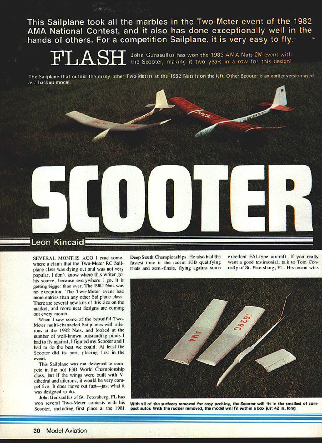
This sailplane took all the marbles in the Two-Meter event of the 1982 AMA National Contest, and it also has done exceptionally well in the hands of others. For a competition sailplane, it is very easy to fly.
FLASH: John Gunsaullus won the 1983 AMA Nats 2M event with the Scooter, making it two years in a row for this design!
Several months ago I read somewhere a claim that the Two-Meter RC Sailplane class was dying out and was not very popular. I don't know where this writer got his source, because everywhere I go it is getting bigger than ever. The 1982 Nats was no exception. The Two-Meter event had more entries than any other sailplane class. There are several new kits of this size on the market, and more neat designs are coming out every month.
When I saw some of the beautiful Two-Meter multi-channeled sailplanes with ailerons at the 1982 Nats, and looked at the number of well-known outstanding pilots I had to fly against, I figured my Scooter and I had to do the best we could. At least the Scooter did its part, placing first in the event.
This sailplane was not designed to compete in the hot F3B World Championship class, but if the wings were built with V-dihedral and ailerons, it would be very competitive. It does move out fast—just what it was designed to do.
John Gunsaullus of St. Petersburg, FL has won several Two-Meter contests with his Scooter, including first place at the 1981 Deep South Championships. He also had the fastest time in the recent F3B qualifying trials and semi-finals, flying against some excellent FAI-type aircraft. If you really want a good testimonial, talk to Tom Connelly of St. Petersburg, FL. Wins when flying his Scooter in the Two-Meter and Unlimited classes have quickly taken him out of the Sportsman class and into Expert. Ed Wright, Jr. of Tampa, FL has also won several first places, including the 1981 Tangerine Championships.
You get out of a model what you put into it. For the ultimate in competition (but still exceptionally easy to fly), the Scooter is worth the work it takes to build. First place at the 1982 Nats against some really hot competition is the best proof I can give you.
General
Here are a few things you should and shouldn't do:
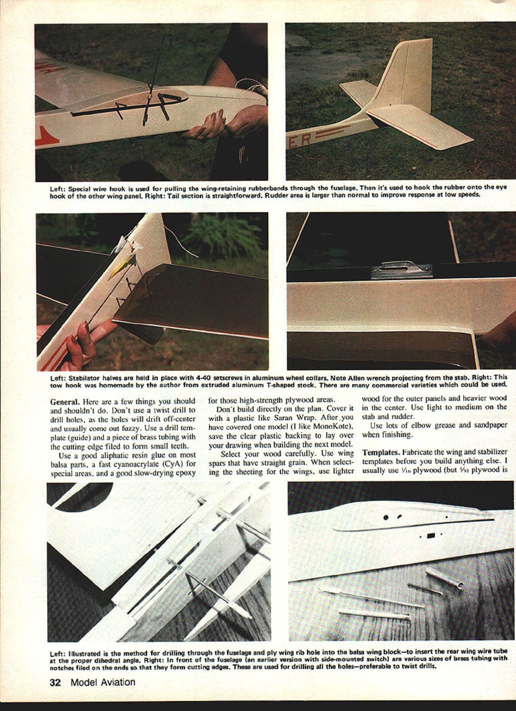
- Don't use twist drills to drill holes; holes will drift off-center and usually come out fuzzy. Use a drill template (guide) and a piece of brass tubing with the cutting edge filed to form small teeth.
- Use a good aliphatic resin glue on most balsa parts, a fast cyanoacrylate (CyA) for special areas, and a good slow-drying epoxy for high-strength plywood areas.
- Don't build directly on the plan. Cover it with a plastic like Saran Wrap. After you have covered one model (I like MonoKote), save the clear plastic backing to lay over your drawing when building the next model.
- Select your wood carefully. Use wing spars that have straight grain. When selecting the sheeting for the wings, use lighter wood for the outer panels and heavier wood in the center. Use light-to-medium wood on the stabilizer and rudder.
- Use lots of elbow grease and sandpaper when finishing.
Templates
Fabricate the wing and stabilizer templates before you build anything else. I usually use 1/8-in. plywood for templates.
Cut out the master wing airfoil template first, but don't drill any holes yet. Next, cut a W1 wing rib template. It should be 1/16 in. smaller than the master airfoil template. Drill W1 first, then locate and clamp W1 on the master airfoil template, and drill the master.
You now have an accurate master to lay on the fuselage sides for drilling the wing wire tube holes in the proper location. It also serves to contour the top of the fuselage to the airfoil shape. However, don't build the wing or the fuselage yet.
Construct a stab drill rib template next. The stab template is not only used to drill the stab ribs, but also the stab horn.
Vertical fin and rudder
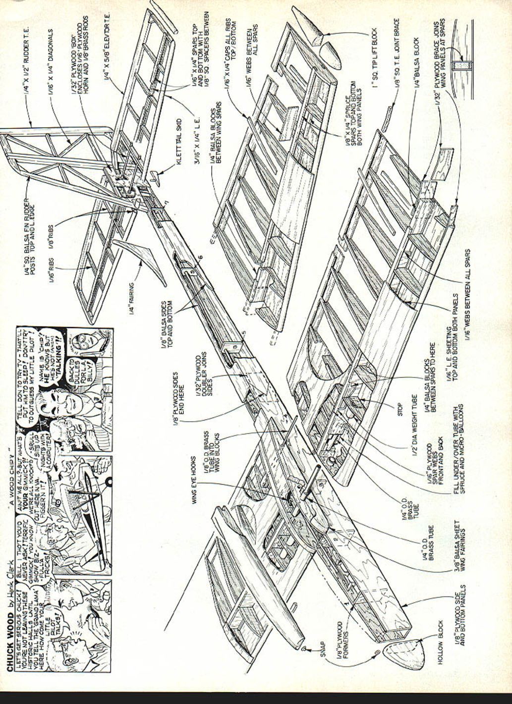
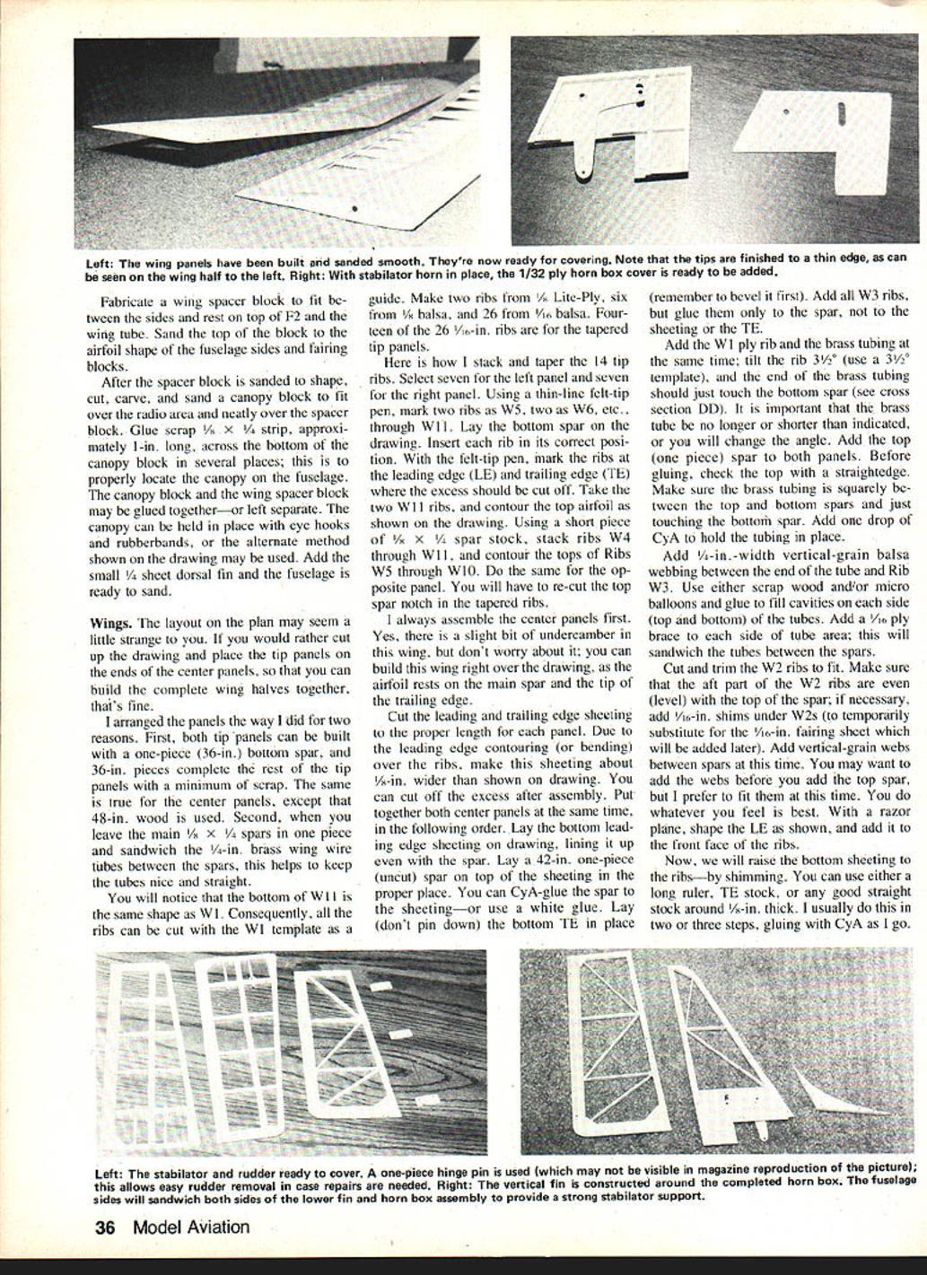
Cut out the two 1/32-in. ply horn box sides (shaded area) as shown on the drawing. Drill and slot for the stab bearing and rear wire clearance. Lay one side of the ply box down, and build a 1/16-in. spacer frame around the outside edge. When you add the second side, it should add up to 1/4 in. (rudder thickness). If okay, remove the top side for adding the horn bearing and horn, then glue the top ply section in place. Quickly stick a piece of 3/32-in. wire in the stab-horn bearing.
Using a square, make sure the sides are aligned and the wire is 90° to the sides of the horn box. You don't want a crooked stab in relationship with the rudder! Also make sure the horn remains free and movable. When dry, sand the front and back square; lay it on the drawing, and construct the vertical fin and movable rudder around the horn box. Leave the small dorsal fin off at this time.
Since all rudder parts and ribs are 1/8 in. wide, and the trailing edge stock is around 1/8 to 3/16 in., add the trailing edge by shimming to the center of the ribs. After the glue has dried, trim and sand the ribs, top and bottom, to fair in with the trailing edge. You can now construct the fuselage.
Fuselage
I recommend that the forward fuselage sides (plus the bulkheads, W1 wing ribs, and four stab ribs) be cut from Lite-Ply plywood, available from Sig. This is lightweight, and it is so easy to cut—even without a jigsaw. Whether you use Lite-Ply or regular 1/8-in. ply, cut your fuselage sides as shown. Use ply forward of the splice, and balsa from the splice to the rear.
Use the master airfoil template to locate the wing wire tube holes, and drill the holes as required. Sand the fuselage sides together with the brass wing tubes in place. The master airfoil templates will also help you to sand the airfoil shape on the top of the fuselage sides. Cut the fuselage bottom which is also 1/8-in. ply for the forward one-third and 3/16-in. balsa for the rear two-thirds. Next, cut out the bulkheads and the nose block. The nose block is constructed from three pieces of 3/8-in. basswood, with the center section cut out so that you can add lead for ballast. Taper the outside of the nose block as shown on the plans.
Lay the fuselage bottom on the drawing. Glue on the nose block, all the bulkheads, and set the rudder and horn box assembly in place. Notice the fin leading edge just barely rests on Bulkhead F7. When this part is dry, add the stab pushrod outer housing through the bulkheads, ending in F7. Add the inner pushrod and metal horn clevis. Make sure the pushrod and horn operate freely.
Add the fuselage sides. Install a piece of 1/8-in. brass tubing through the wing wire tube holes to help align the sides. I usually make a template from a piece of 3-in.-sq. balsa sheet, cutting one side to about 91°. Use the template to check the angle between tubing and fuselage sides. The fuselage is straight from F2 to F7. When the angle is the same on both sides, clamp the sides around the F3 area. Clamp the fuselage sides to the lower ply box area of the rudder with a small C-clamp or clothespins. Finally, clamp the sides to the nose block. Add other clamps and/or pins as required. I use a slow-drying epoxy (Hobby Poxy #2) for the sides, as it allows me enough time to align everything before the glue sets up.
You can now add the rudder pushrod, etc. Note that both outer pushrod housings (with inner rods in place) can be "snapped" up and out of F2 for later insertion of the radio receiver. You may want to run the antenna tube through the fuselage side. I usually run my antenna tube to a 3/16-in. hole in the fuselage side; after covering, I slit the MonoKote, reach in with a small hook, and pull out the antenna.
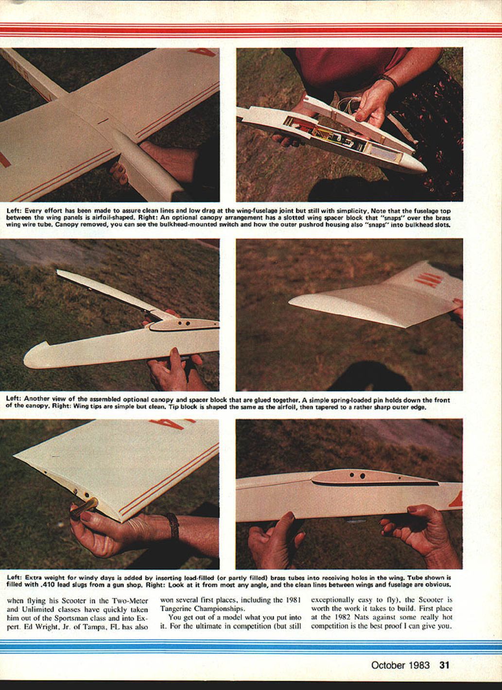
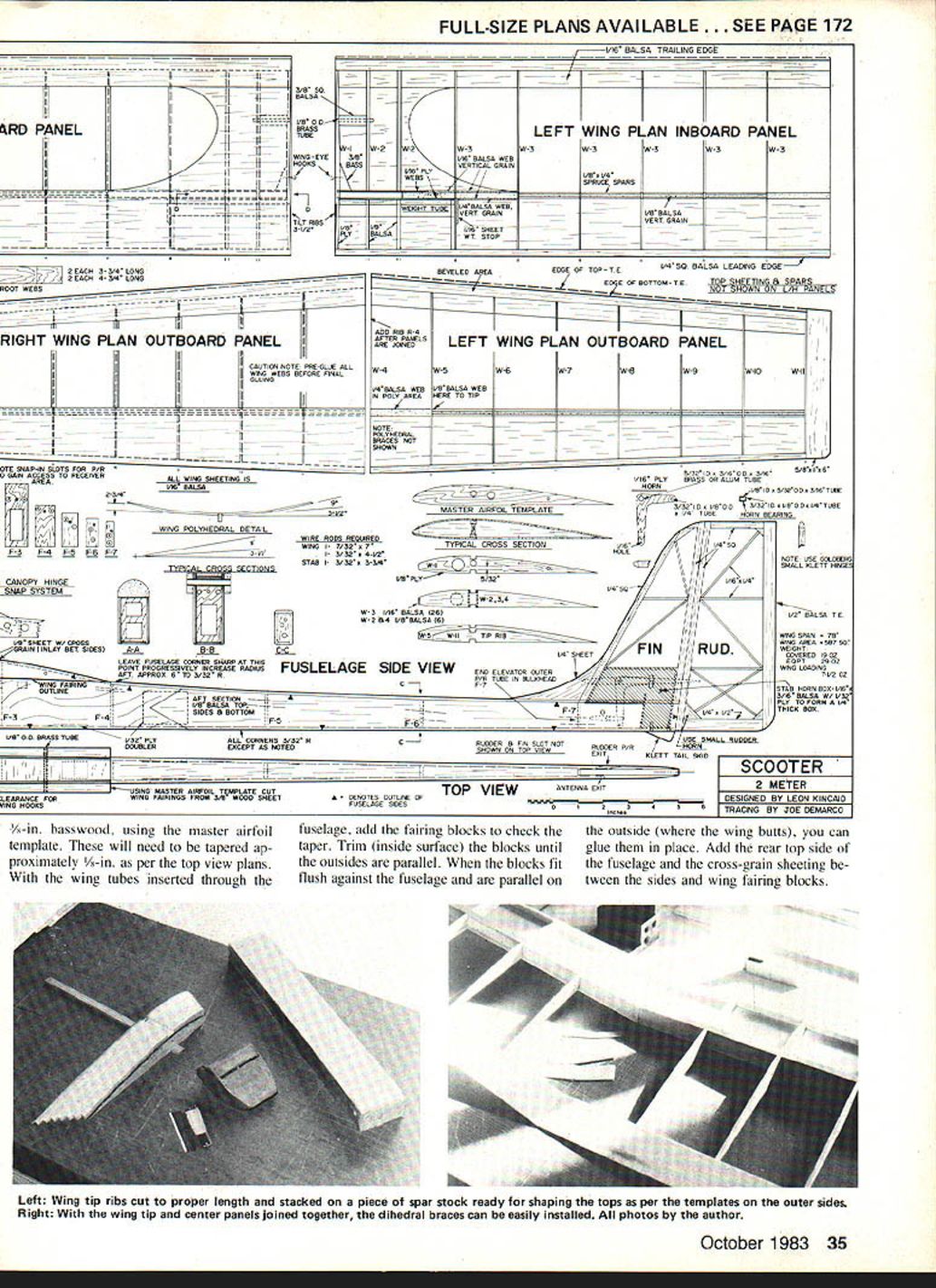
Cut out the two wing fairing blocks from 3/8-in. balsa. Use 1/8-in. basswood, using the master airfoil template. These will need to be tapered approximately 5/8 in. as per the top view plans. With the wing tubes inserted through the fuselage, add the fairing blocks to check the taper. Trim the inside surface of the blocks until the outsides are parallel. When the blocks fit flush against the fuselage and are parallel on the outside (where the wing butts), glue them in place. Add the rear top side of the fuselage and the cross-grain sheeting between the sides and wing fairing blocks.
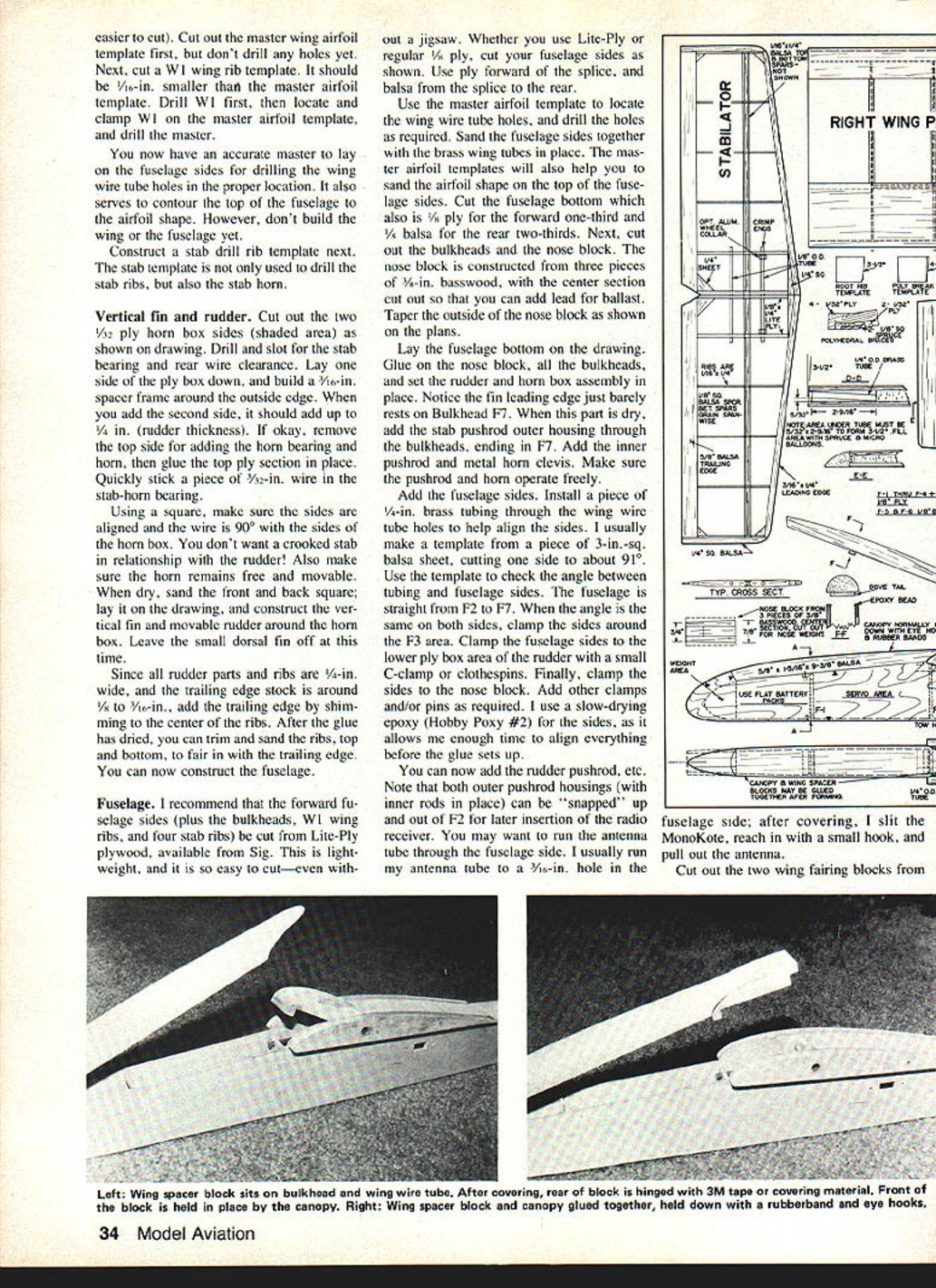
Fabricate a wing spacer block to fit between the sides and rest on top of F2 and the wing tube. Sand the top of the block to the airfoil shape of the fuselage sides and fairing blocks.
After the spacer block is sanded to shape, cut, carve, and sand a canopy block to fit over the radio area and neatly over the spacer block. Glue scrap 1/8 x 1/4-in. strip, approximately 1 in. long, across the bottom of the canopy block in several places; this is to properly locate the canopy on the fuselage. The canopy block and the wing spacer block may be glued together—or left separate. The canopy can be held in place with eye hooks and rubber bands, or the alternate method shown on the drawing may be used. Add the small 1/4-in. sheet dorsal fin and the fuselage is ready to sand.
Wings
The layout on the plan may seem a little strange. If you would rather cut up the drawing and place the tip panels on the ends of the center panels, so that you can build the complete wing halves together, that's fine.
I arranged the panels the way I did for two reasons. First, both tip panels can be built with a one-piece (36-in.) bottom spar, and 36-in. pieces complete the rest of the tip panels with a minimum of scrap. The same is true for the center panels, except that 48-in. wood is used. Second, when you leave the main 1/8 x 1/4-in. spars in one piece and sandwich the 1/4-in. brass wing wire tubes between the spars, this helps to keep the tubes nice and straight.
You will notice that the bottom of W11 is the same shape as W1. Consequently, all the ribs can be cut with the W1 template as a guide. Make two ribs from 1/8-in. Lite-Ply, six from 3/32-in. balsa, and 26 from 1/8-in. balsa. Fourteen of the 26 3/32-in. ribs are for the tapered tip panels.
Here is how I stack and taper the 14 tip ribs. Select seven for the left panel and seven for the right panel. Using a thin-line felt-tip pen, mark two ribs as W5, two as W6, etc., through W11. Lay the bottom spar on the drawing. Insert each rib in its correct position. With the felt-tip pen, mark the ribs at the leading edge (LE) and trailing edge (TE) where the excess should be cut off. Take the two W11 ribs, and contour the top airfoil as shown on the drawing. Using a short piece of 1/8 x 1/4-in. spar stock, stack ribs W4 through W11, and contour the tops of ribs W5 through W10. Do the same for the opposite panel. You will have to re-cut the top spar notch in the tapered ribs.
I always assemble the center panels first. Yes, there is a slight bit of undercamber in this wing, but don't worry about it; you can build this wing right over the drawing, as the airfoil rests on the main spar and the tip of the trailing edge.
Cut the leading and trailing edge sheeting to the proper length for each panel. Due to the leading edge contouring (or bending) over the ribs, make this sheeting about 1/8 in. wider than shown on the drawing. You can cut off the excess after assembly. Put together both center panels at the same time, in the following order:
- Lay the bottom leading edge sheeting on the drawing, lining it up even with the spar.
- Lay a 42-in. one-piece (uncut) spar on top of the sheeting in the proper place. You can CyA-glue the spar to the sheeting—or use a white glue.
- Lay (don't pin down) the bottom TE in place (remember to bevel it first). Add all W3 ribs, but glue them only to the spar, not to the sheeting or the TE.
- Add the W1 ply rib and the brass tubing at the same time; tilt the rib 3-1/2° (use a 3-1/2° template), and the end of the brass tubing should just touch the bottom spar (see cross section DD). It is important that the brass tube be no longer or shorter than indicated, or you will change the angle.
- Add the top (one-piece) spar to both panels. Before gluing, check the top with a straightedge. Make sure the brass tubing is squarely between the top and bottom spars and just touching the bottom spar. Add one drop of CyA to hold the tubing in place.
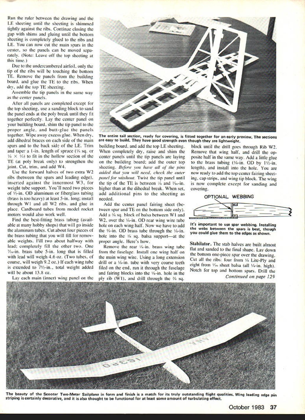
- Add 1/4-in.-width vertical-grain balsa webbing between the end of the tube and Rib W3. Use either scrap wood and/or microballoons and glue to fill cavities on each side (top and bottom) of the tubes. Add a 1/16-in. ply brace to each side of the tube area; this will sandwich the tubes between the spars.
Cut and trim the W2 ribs to fit. Make sure that the aft part of the W2 ribs is even (level) with the top of the spar; if necessary, add 1/16-in. shims under W2s (to temporarily substitute for the 1/16-in. fairing sheet which will be added later). Add vertical-grain webs between spars at this time. You may want to add the webs before you add the top spar, but I prefer to fit them at this time. With a razor plane, shape the LE as shown, and add it to the front face of the ribs.
Now raise the bottom sheeting to the ribs—by shimming. You can use either a long ruler, TE stock, or any good straight stock around 1/8 in. thick. I usually do this in two or three steps, gluing with CyA as I go.
Run a ruler between the drawing and the LE sheeting until the sheeting is shimmed tightly against the ribs. Continue closing the gap with shims and gluing until the bottom sheeting is completely glued to the ribs and LE. You can now cut the main spars in the center, so the panels can be moved separately. (Note: Leave off the top sheeting at this time.)
Due to the undercambered airfoil, only the tip of the ribs will be touching the bottom TE. Remove the panels from the building board, and glue the TE to the ribs. When dry, add the top TE sheeting.
Assemble the tip panels in the same way as the center panels.
After all panels are completed except for the top sheeting, use a sanding block to sand the panel ends at the poly break until they fit together perfectly. Lay the center panel on your building board, shim the tip panel to the proper angle, and butt-glue the panels together. Wipe away excess glue. When dry, add dihedral braces on each side of the main spars and to the back side of the LE. Trim and taper a 1-in. length of spruce (1/2 sq. or 1/4 x 1/4) to fit in the hollow section of the TE (at the poly break only) to strengthen the joint. Cut, trim, and add W4.
Use the forward halves of two extra W2 ribs (between the spars and leading edge), inserted against the innermost W3, for weight tube support. You'll need two pieces of 1/2-in. OD aluminum or fiberglass tubing (brass is too heavy) at least 5 in. long; install through W1 and all W2 ribs, and glue in place. Cardboard tubes from model rocket motors would also work well.
Find the best-fitting brass tubing (available at many hobby shops) that will go inside the aluminum tubes. Cut about four pieces of the brass tubing that you will fill for removable weights. Fill two about halfway with lead; completely fill the other two. One 7/16-in. brass tube 5 in. long that is filled with lead will weigh 4.6 oz. (Two tubes, of course, will weigh 9.2 oz.) If each wing tube is extended to 7-1/2 in., total weight added will be about 13.8 oz.
Lay each main (inner) wing panel on the building board, and add the top LE sheeting. When completely dry, raise and shim the center panels until the tip panels are laying on the building board; add the outer top sheeting. Before you have all of the pins added that you will need, check the outer panel for washout. Twist the tip panel until the tip of the TE is between 1/32 and 1/16 in. higher than at the dihedral break. When set, add additional pins to the sheeting as needed.
Add the center panel fairing sheet (between spar and TE on the bottom side only). Add a 3/8-in. square block of balsa between W1 and W2, over the 1/8-in. OD rear wing wire tube hole on each wing half. Now add the 1/8-in. OD brass tube through the 1/8-in. hole into the 3/8-in. square balsa support—at the proper angle.
Remove the rear 1/8-in. brass wing tube from the fuselage. Install one wing half on the main wing wire. Using a long extension drill or a 1/8-in. tube with very coarse teeth filed on the end, run it through the fuselage and fairing blocks into the 1/8-in. hole in the ply rib (W1), and drill through the 3/8-in. square block until the drill goes through Rib W2. Remove that wing half, and drill the opposite half in the same way. Add a little glue to the brass tubing (1/8-in. OD by 1-1/2-in. length), and install into the hole.
You are now ready to add the top center fairing sheeting, cap strips, and wing tip block. The wing is now complete except for sanding and covering.
Stabilator
The stab halves are built almost flat and sanded to the final shape. Lay down the bottom one-piece spar over the drawing. Cut all the ribs: four from 1/8-in. Lite-Ply and eight from 1/16-in. sheet balsa (all 1/4 in. high). Notch for top and bottom spars. Drill the Lite-Ply ribs using the stab template you used previously to drill the stab horn.
Note: If you didn't use Lite-Ply on the fuselage and wing ribs, and used instead heavy 5-ply plywood, please don't use this heavy plywood on the stab. Use either 1/8-in. ply or 1/16-in. ply plus 1/8-in. balsa.
Shim the 1/16 x 1/4-in. LE up 1/32 in. to center it. With aluminum tubes installed (not glued), install the ply ribs to the bottom spar. Add remaining ribs by cutting the forward length to fit. Add tapered 1/4-in. sq. stock between the ply ribs and the LE. Add the TE by either shimming or just "eye-balling" to ensure the TE is located in the center of the 1/4-in. rib. Add 1/8-in. sq. pieces (by 11/16-in. length) on the bottom spar between each rib; this will add a lot of strength. Add the top spar, gussets, and tip blocks. Cut the center to separate the two halves. Add optional aluminum collars, glue tubes in place, and you are ready to sand it.
Finishing
There are two things that usually set off a plane and make certain ones look so much better than others: a lot of sanding and a neat covering job. John Hunton wrote an article that was in Model Aviation around a year ago about making and using sanding blocks; that's what I do. You can usually find a piece of 1 x 2 or 1 x 3 hardwood about 10 to 12 in. long. Using contact cement (if available), add coarse paper to one side and fine on the other.
I have indicated on the drawing the basic shapes to be sanded. The most important part to sand is the wing leading edge. I usually rough it close with a razor plane, make a female template for about the forward 25% of the airfoil, and sand the final shape with my sanding block. Sanding the LE sharper will not make the Scooter fly faster—only stall quicker. On forming and sanding the wing tip block, shape it the same as the airfoil top and bottom (looking at the end view of the wing). Looking from the front view, shape it as shown in section EE. The tip is easy to shape and sand, but sometimes it is difficult to cover. However, I believe this shape gives the Scooter its maximum lift on tow and minimum drag in flight.
Sanding the stab and rudder is much the same. Carve or plane away all excess wood, and sand the surfaces using the maximum length of the sanding block.
(End of article text provided.)
Transcribed from original scans by AI. Minor OCR errors may remain.

