
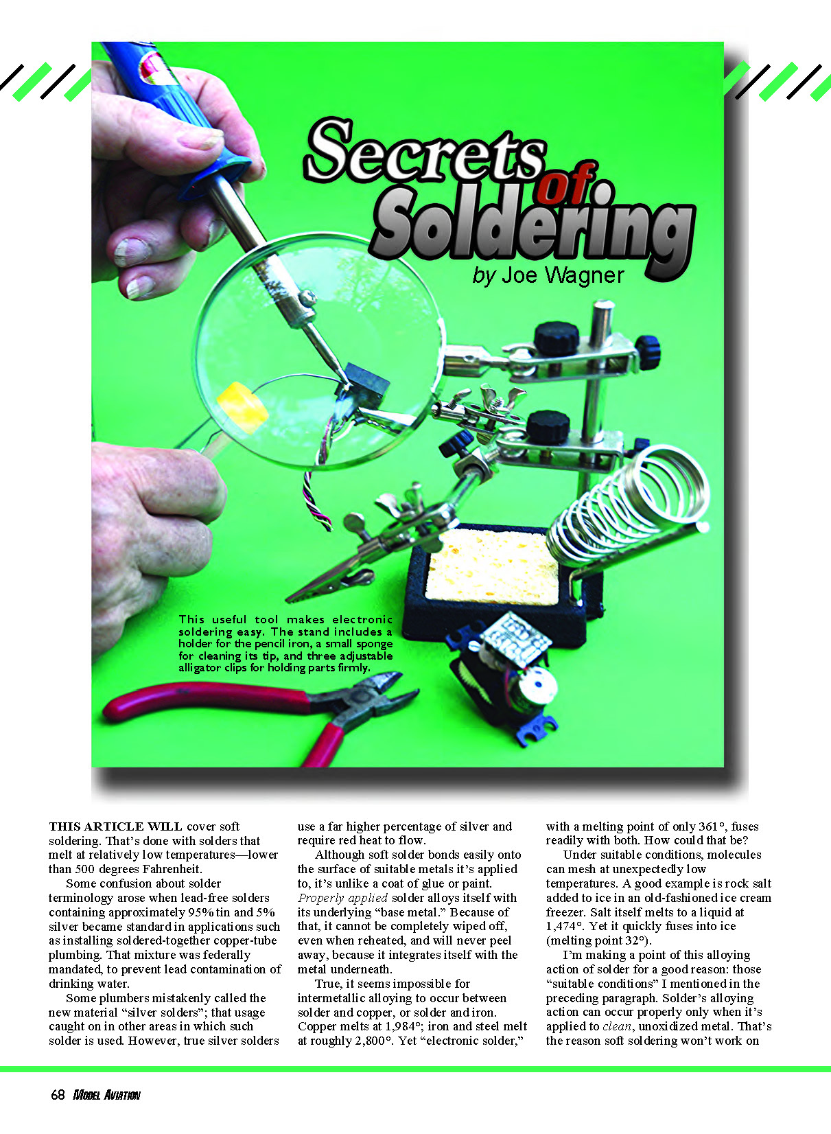
Secrets of Soldering
by Joe Wagner
This article will cover soft soldering. That's done with solders that melt at relatively low temperatures—lower than 500°F.
Some confusion about solder terminology arose when lead-free solders containing approximately 95% tin and 5% silver became standard in applications such as installing soldered-together copper-tube plumbing. That mixture was federally mandated to prevent lead contamination of drinking water.
Some plumbers mistakenly called the new material "silver solders"; that usage caught on in other areas in which such solder is used. However, true silver solders use a far higher percentage of silver and require red heat to flow.
Although soft solder bonds easily onto the surface of suitable metals it's applied to, it's unlike a coat of glue or paint. Properly applied solder alloys itself with its underlying "base metal." Because of that, it cannot be completely wiped off, even when reheated, and will never peel away, because it integrates itself with the metal underneath.
True, it seems impossible for intermetallic alloying to occur between solder and copper, or solder and iron. Copper melts at 1,984°F; iron and steel melt at roughly 2,800°F. Yet "electronic solder," with a melting point of only 361°F, fuses readily with both. How could that be?
Under suitable conditions, molecules can mesh at unexpectedly low temperatures. A good example is rock salt added to ice in an old-fashioned ice cream freezer. Salt itself melts to a liquid at 1,474°F. Yet it quickly fuses into ice (melting point 32°F).
I'm making a point of this alloying action of solder for a good reason: those "suitable conditions" I mentioned above. Solder's alloying action can occur properly only when it's applied to clean, unoxidized metal. That's the reason soft soldering won't work on stainless steel or aluminum. Both of those metals owe their corrosion resistance to the fact that a thin, transparent oxide film automatically forms on their surfaces. (Aluminum and stainless steel can be soldered using special solders and fluxes, but that's outside the scope of this article.)
Cleanliness and absence of oxidation is the key to successful soft soldering. That applies not only to the metals to be joined, but also to the soldering iron's tip. When in use, that tip gets hotter than 500°F and its surface oxidizes rapidly. That's why one of the most important "tools" used in soft soldering is a cleaning sponge for the iron tip. A cellulose sponge that is well moistened with plain water makes an ideal wipe-and-clean instrument for soldering-iron tips. The moisture prevents the hot tip from scorching or melting the sponge as you rub the iron tip across it immediately before soldering. But don't let your sponge get dripping wet; that would cool the iron's tip too much while you were wiping it.
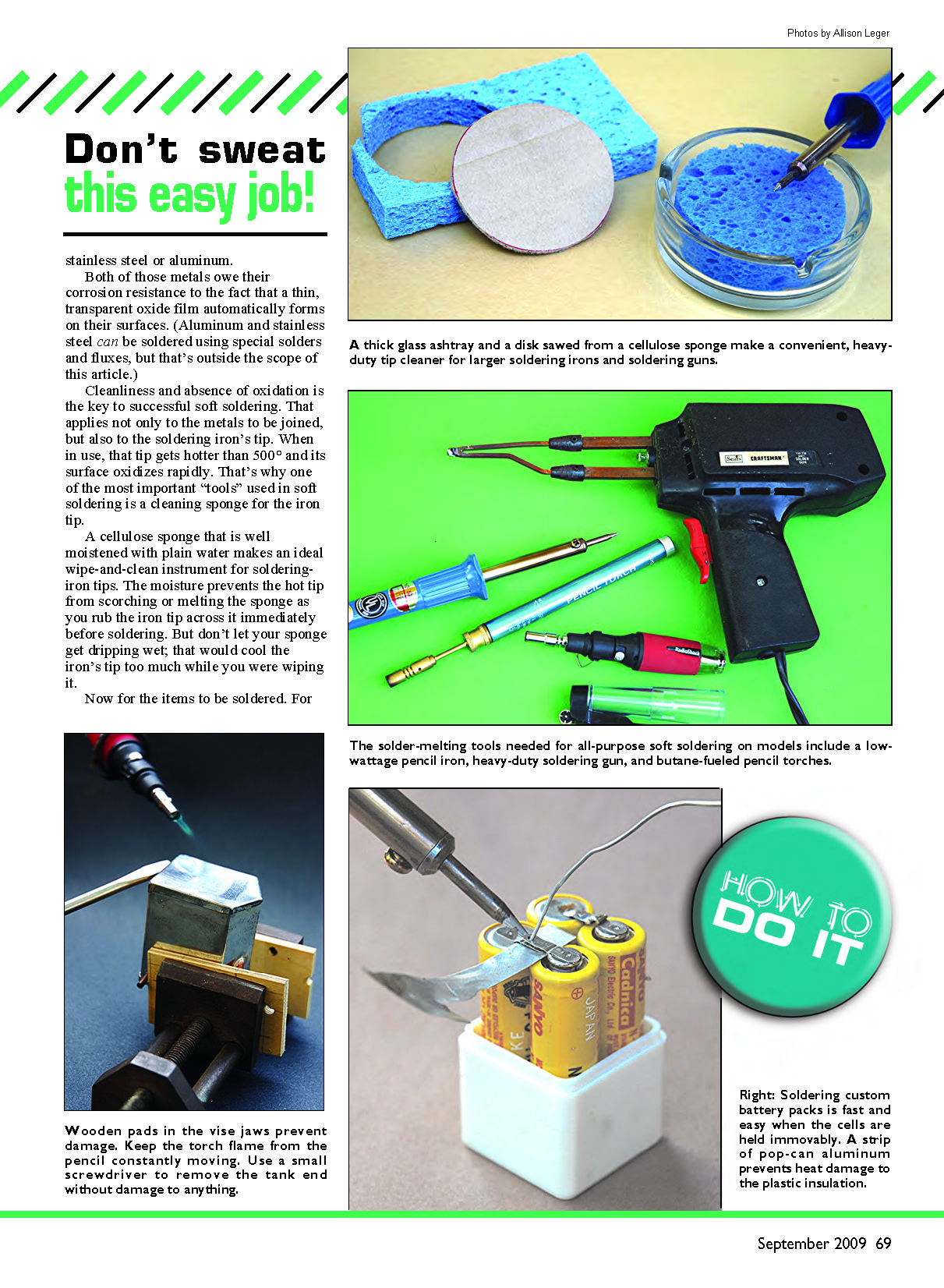
Keeping hot soldering-iron tips bright and clean in use is vital for producing strong, reliable joints. That's why "soldering kits" and iron holders often come with a sponge in a small compartment on the base. Those work well for occasional electronic soldering tasks. But for jobs requiring larger, high-wattage irons—such as landing gear assembly—I've found a much handier "wet sponge holder."
As shown in my setup, my holder uses a heavy glass ashtray for its base. That's massive enough to resist being dislodged by wiping the tip of a big pistol-grip soldering gun on it. I cut the sponge within from an inexpensive cellulose kitchen type that supermarkets sell. The dry sponge, fresh from its package, is rigid enough that I can accurately shape it with a band saw or a scroll saw. I made a circular pattern from cardboard, roughly 10% smaller than the ashtray cavity, to allow for the sponge to expand when wet. I used a felt-tip pen to trace around that pattern on the sponge, and then I sawed out the disk and popped it into its glass base. That's all it takes.
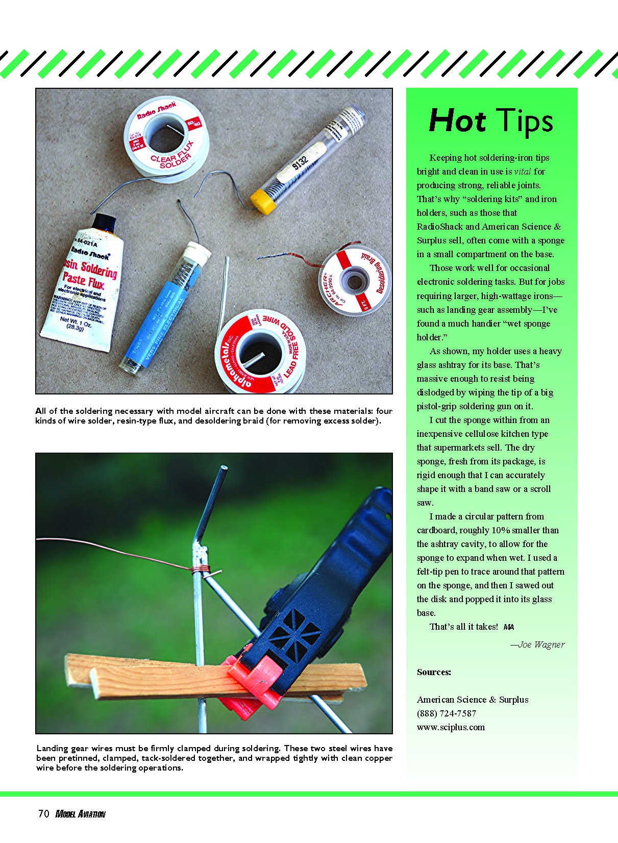
All of the soldering necessary with model aircraft can be done with these materials:
- Four kinds of wire solder
- Resin-type flux
- Desoldering braid (for removing excess solder)
For the strongest and most reliable junctions, it's best to clean the areas you want to join to oxide-free brightness. Wipe them with a solvent-wetted paper towel to remove any oily film, and then scour with fine sandpaper to remove all surface oxide. Immediately apply a small amount of resin-type flux.
Flux is a pasty compound that, when heated by the soldering iron, becomes a thin liquid that flows over the surfaces of the joint to be soldered and prevents oxidation. Never use acidic flux for soft soldering; it can cause corrosion in the joint. Worse yet, when heated, its vapors often induce rust on any steel tools in the vicinity.
Use this cleaning-and-fluxing procedure with piano wire; copper, brass, and steel sheet metal; copper tubing; and the like. However, most small-gauge wire used in electric and electronic components has been pre-tinned; its copper strands are coated with bright tin at the factory. Any electrical wire with this silvery coating needs no further "tinning."
For the "tinning" method, two of molten solder's unusual characteristics come into play, one of which is its extremely low viscosity. As well as penetrating oil, molten solder will make its way swiftly into the smallest crevices, and it flows most readily toward the hottest area—even uphill. That's the reason behind the long-established advice to place the iron tip on one end of the area to be soldered and then apply the solder itself at the other end. When everything heats enough throughout the juncture, the solder melts and rapidly flows into and through the assembly, toward the iron tip.
However, for tinning, it's usually best to apply solder directly onto the iron as I press it against the surface to be tinned. That speeds the heating process considerably. The melted solder provides a large heat-transfer area between the hot iron tip and the cooler base metal. Also, the hot tip can be used like a brush, to smoothly spread the solder over the areas where tinning is needed.
Firmly clamp items to be soldered before applying heat. I prefer to use wooden surfaces for clamping the metal parts. That reduces heat loss from conductivity.
During the tinning operation, firm clamping makes an easy job of wiping off all but a thin surface coat of solder from the just-tinned areas. (We don't want or need blobs of solder on our work; it adds no strength and looks amateurish.)
Furthermore, after tinning, when the actual soldering assembly is being done, firm clamping is even more essential. If any movement whatever occurs in a solder joint before its solder has fully solidified, a weak and unreliable junction will result. The parts to be connected must be kept motionless until the solder cools, or it will become embrittled.
You can see the difference between a good solder joint and a bad one. If the solder has a frosty surface appearance, the intersection is faulty. Its solder is weak and brittle, rather than strong and ductile. This can be easily corrected by reheating the joint until the solder melts and keeping everything motionless until the solder cools.
Electrical / Electronic
- Rosin-core electronic solder seldom requires additional fluxing.
- Use only low-power—15- to 30-watt—irons to solder flexible wires, because excessive heat causes solder to "wick" along the wire. That spoils its flexibility and could even cause the wire to fracture if vibration and/or repeated flexure occurs. Whenever you solder stranded wire, hold the iron tip against the junction just until the solder flows. Then quickly remove the iron and blow on the solder to cool it.
- When assembling Ni-Cd and NiMH battery packs, it helps greatly to hold the individual cells together firmly as you make their soldered interconnections. For AA-size cells, I use leftover plastic case halves from old Heathkit and Ace R/C battery packs. For cells of other sizes, I make temporary holders from scrap wood. Tape doesn't provide as reliable an alignment as I would like.
- Also, to keep heat from melting the cells' plastic insulation and possibly causing a short circuit, insert a strip of thin sheet aluminum under each pair of cell tabs before soldering them. That also acts as a temporary support to keep the tabs from separating while being soldered.
Structural (Landing Gear, Wing Struts, Etc.)
- A solder gun or a mini butane gas-powered iron is needed for this kind of work. The amount of heat required is far beyond a small "pencil-type" soldering iron's capacity. And instead of electronic solder, use refrigeration solder or one of the lead-free types containing silver for this kind of application. Maximum mechanical strength is vital.
- Strong, dependable soldered joints involving steel music wire, bicycle spokes, etc., need each juncture to be assembled in five stages:
- Clean and pretin all areas of the wire that will be soldered. (Electronic-grade solder is fine for this because of its strong alloying ability.)
- Clamp two adjoining sections of wire together firmly in accurate alignment.
- "Tack-solder" the wires to each other with a thin layer of solder.
- Tightly wrap the joint with copper wire.
- Neatly fill each wire-wrapped assembly with more solder.
- For applications such as wire cabane struts for biplanes, sheet-brass reinforcements and/or attachment plates might be required. If so, follow the first three steps and then cut and preform the required plates. Firmly clamp the parts together and solder. Use enough solder to form a visible fillet at each juncture, but don’t pile on a blob.
Caption: Landing gear wires must be firmly clamped during soldering. These two steel wires have been pretinned, clamped, tack-soldered together, and wrapped tightly with clean copper wire before the soldering operations.
Fuel System
- Copper and brass tubing can usually be soldered with a 30- to 45-watt iron. (I seldom use brass tubing in my glow fuel systems, because I’ve found that any alloy containing zinc will catalyze methanol into acetic acid: a potent rust inducer.)
- Metal fuel tanks for model engines usually have too much surface area for a pencil-type iron to heat adequately and produce a reliable, leakproof assembly. A solder gun is needed; however, electronic solder works nicely in model fuel tanks, and its extra ductility is a plus.
- The only way to go for disassembly is with a small butane-fueled "pencil torch." Use it like an airbrush, to evenly heat the rim of the tank end. When the entire edge of the tank is hot enough, inserting the tip of a small screwdriver under the tank end’s "lip" will let you flip the end free without damaging anything.
- I routinely disassemble nearly all of my metal fuel tanks before using them, to ensure that there is no unwanted "crud" inside. In addition, I might want to relocate one or more of the fuel tubes inside the tank—or replace brass tubing with copper.
Other Applications
- Soldered-on washers make excellent retainers for small pushrods and wheels. Since brass washers in the sizes I need are almost impossible to find, I make my own. Using thin-gauge (.010–.020) brass sheet from K&S, I drill a series of holes along one edge to fit the wire I'm using—one hole for every washer I'll need and a few spares. Then I use a hand-operated paper punch (it looks like a cheap pair of pliers) to make holes in the finished washers, one by one, from the perforated brass sheet. Centering the washers is easy to do visually; concentricity isn't needed.
- Before soldering each retaining washer onto its wire, I press a scrap of card stock, torn from a magazine's reply card, onto the pretinned protruding end of the pushrod or wheel axle. Then I add the washer and solder it in place. I tear away the scrap of card stock after that, since it has done its double duty of providing clearance space between the washer and the item it retains and soaking up surplus flux that might otherwise flow down the axle and gum up the free-pivoting action.
- "Fairleads" for control-line pushrods and anchor points for biplane rigging and similar uses can be made from wire loops or brass washers. Solder them on edge into deep slots sawed into the ends of cutoff brass machine screws.
Joe Wagner [email protected]
Sources
- American Science & Surplus — (888) 724-7587 — www.sciplus.com
- RadioShack — (800) 843-7422 — www.radioshack.com
- K&S Engineering — (773) 586-8503 — www.ksmetals.com
Transcribed from original scans by AI. Minor OCR errors may remain.

