
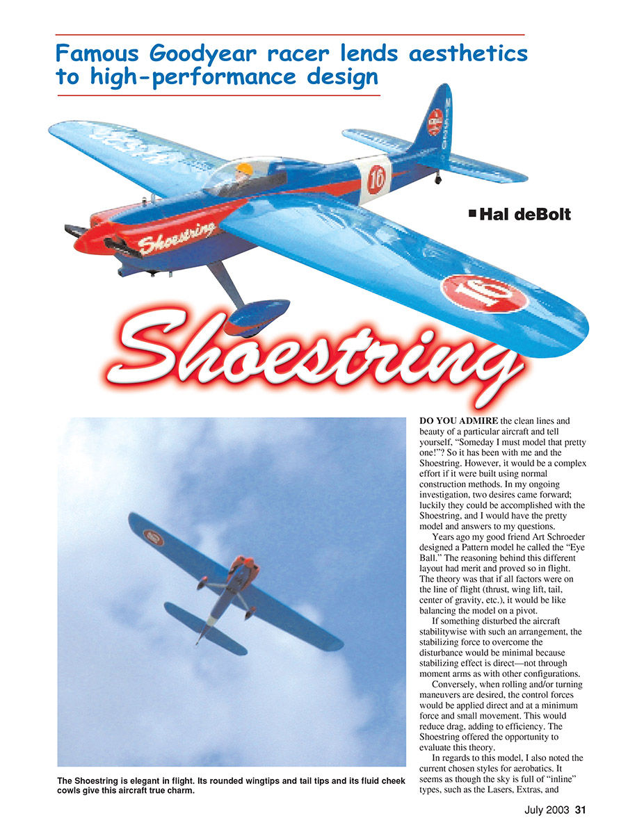
Shoestring
Famous Goodyear racer lends aesthetics to high-performance design
Hal deBolt
Do you admire the clean lines and beauty of a particular aircraft and tell yourself, “Someday I must model that pretty one”? So it has been with me and the Shoestring. However, it would be a complex effort if it were built using normal construction methods. In my ongoing investigation, two desires came forward; luckily they could be accomplished with the Shoestring, and I would have the pretty model and answers to my questions.
Years ago my good friend Art Schroeder designed a Pattern model he called the “Eye Ball.” The reasoning behind this different layout had merit and proved so in flight. The theory was that if all factors were on the line of flight (thrust, wing lift, tail, center of gravity, etc.), it would be like balancing the model on a pivot.
If something disturbed the aircraft stability-wise with such an arrangement, the stabilizing force to overcome the disturbance would be minimal because stabilizing effect is direct—not through moment arms as with other configurations.
Conversely, when rolling and/or turning maneuvers are desired, the control forces would be applied direct and at a minimum force and small movement. This would reduce drag, adding to efficiency. The Shoestring offered the opportunity to evaluate this theory.
In regards to this model, I also noted the current chosen styles for aerobatics. It seems as though the sky is full of “inline” types, such as the Lasers, Extras, and Sukhois. Wouldn't it be nice to see something different?
We have learned that comparative investigating allows easy judgment of superiority. Does an inline type have an advantage compared to a low-wing model? We wanted a 40-size aircraft, and we were familiar with the Live Wire Cobra—an excellent aerobatic design. Best of all, the Cobra parameters would match the Shoestring. All that was needed was to move the wing from low to shoulder height and change to Shoestring appearance.
The next objective was to find a simpler way to obtain those flowing lines. In the past we had extensively investigated the use of composite, alternate materials for the structure. For that we developed a 1/3-scale RV-4 with a 90%-plastic structure. The rounded fuselage was made from Styrofoam with a fiberglass skin. The fuselage was large, and the mass of foam that was assembled was easy to carve and sand before applying a skin shape.
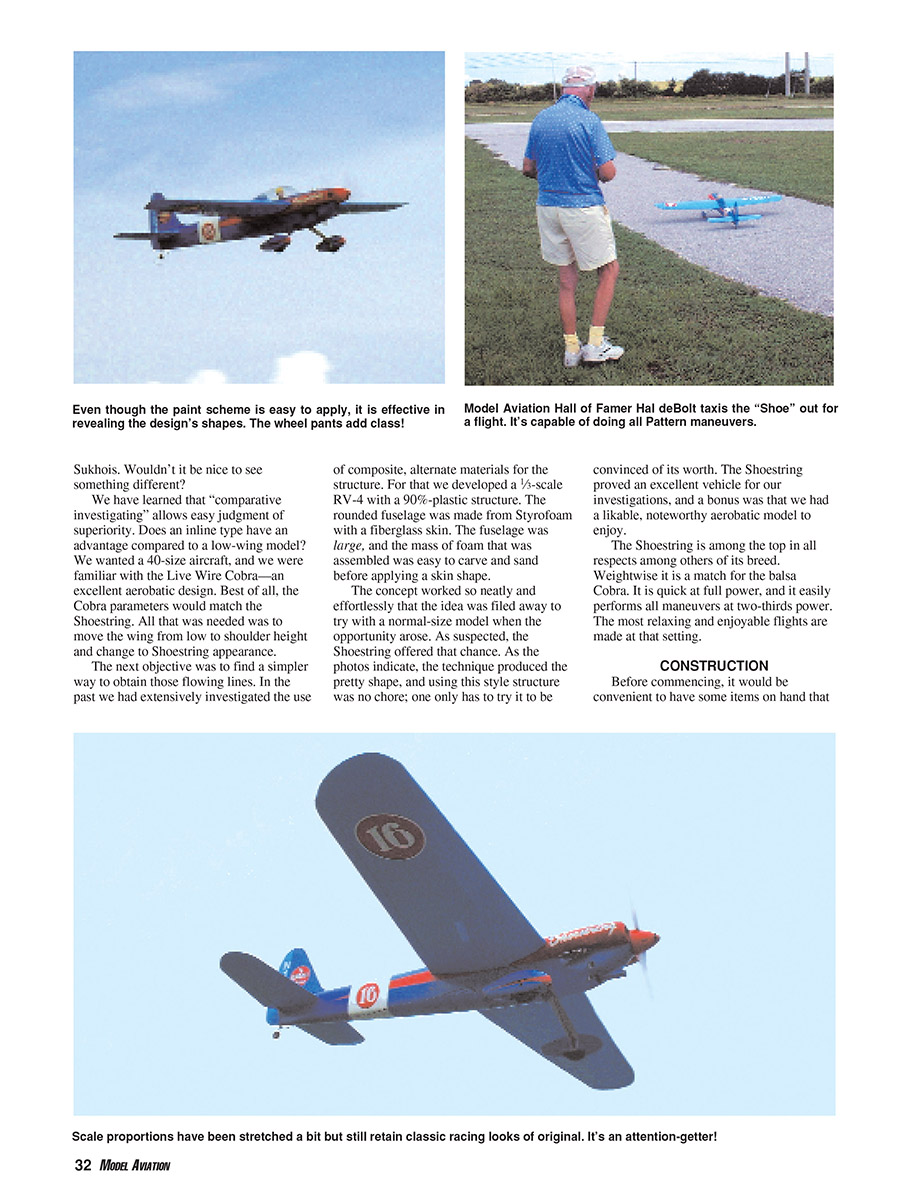
The concept worked so neatly and effortlessly that the idea was filed away to try with a normal-size model when the opportunity arose. As suspected, the Shoestring offered that chance. As the photos indicate, the technique produced the pretty shape, and using this style structure was no chore; one only has to try it to be convinced of its worth. The Shoestring proved an excellent vehicle for our investigations, and a bonus was that we had a likable, noteworthy aerobatic model to enjoy.
The Shoestring is among the top in all respects among others of its breed. Weightwise it is a match for the balsa Cobra. It is quick at full power, and it easily performs all maneuvers at two-thirds power. The most relaxing and enjoyable flights are made at that setting.
CONSTRUCTION
Before commencing, it would be convenient to have some items on hand that this structure requires beyond the normal scratch-building necessities. You'll need:
- 1/2-inch-thick Styrofoam sheet (not the beaded type of foam) from a building-supply center
- Cyanoacrylate (CyA) and aliphatic glues (Titebond, Elmer's, etc.)
- 3-ounce fiberglass cloth and epoxy resin
Tools you will need include:
- A sharp, long-blade carving knife
- A 2 x 15-inch sanding block with 40-grit paper
With any aircraft it is convenient to have the wing and tail available for fitting to the fuselage, so those will be assembled first.
Wing
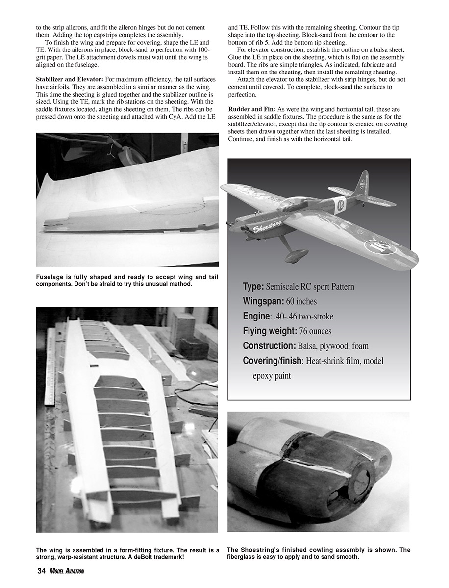
This wing configuration originated with the successful Interceptor Pattern aircraft. The airfoil is progressive, with the excellent NACA 65015 at the center and the extremely stable 65012 at the tips. True alignment is assured by assembling the wing in "saddle fixtures," as is done with full-scale airplanes. The method is simple and quick. We could have used a foam-core wing, but foam is considerably heavier than the balsa wing and we needed to match the Cobra's weight.
Assuming that you have produced the ribs and saddle fixtures, assembly can commence. The wing is one piece, so mark lines on the board at each rib station using the edge of your assembly board and a tri-square. From the center rib front, scribe spanwise lines to represent the leading-edge (LE) taper.
The saddle fixtures have an LE indicator. Aligning the indicator with the LE line, erect saddle fixtures 1, 3, 5, 7, and 9, and lock them in place with spots of CyA. The LE and trailing-edge (TE) sheeting is tapered. Taper the eight sheets as called for on the plans. Install the spanwise 3/16-inch-square fixture strips, which support the sheeting during assembly.
Now comes the easy part. Pin the LE and TE sheeting into the fixtures, and align the sheeting edges with the fixture strips.
The spar is made from 3/32-inch firm-sheet balsa, and it is in halves for simplicity. They are tapered as indicated. The halves are installed at the rear edge of the LE sheeting, and a 1/16-inch plywood joiner is used at the center.
Install all ribs forward and rear. Forget the servo mounting in the center rib for now. Add the LE and TE edge strips, and follow with the bottom sheeting and the rib cap strips.
The basic assembly is completed, and the saddle fixtures ensure positive alignment without constant attention. Remove the wing from the fixtures.
The top of the wing is exposed. Add the needed fill-in sheet at the tips and the top center-section sheeting, but not the bottom yet. Contour the tip shape and blend to the sheeting. With a wide block, sand the angle from the tip to rib 9, then install the lower tip sheeting.
At the center-section, install the servo-compartment pieces to fit your servo, and complete the sheeting. Attach the control horns to the strip ailerons, and fit the aileron hinges but do not cement them. Adding the top cap strips completes the assembly.
To finish the wing and prepare for covering, shape the LE and TE. With the ailerons in place, block-sand to perfection with 100-grit paper. The LE attachment dowels must wait until the wing is aligned on the fuselage.
Stabilizer and Elevator
For maximum efficiency, the tail surfaces have airfoils. They are assembled in a similar manner as the wing. This time the sheeting is glued together and the stabilizer outline is sized. Using the TE, mark the rib stations on the sheeting. With the saddle fixtures located, align the sheeting on them. The ribs can be pressed down onto the sheeting and attached with CyA. Add the LE and TE. Follow this with the remaining sheeting. Contour the tip shape into the top sheeting. Block-sand from the contour to the bottom of rib 5. Add the bottom tip sheeting.
For elevator construction, establish the outline on a balsa sheet. Glue the LE in place on the sheeting, which is flat on the assembly board. The ribs are simple triangles. As indicated, fabricate and install them on the sheeting, then install the remaining sheeting.
Attach the elevator to the stabilizer with strip hinges, but do not cement until covered. To complete, block-sand the surfaces to perfection.
Rudder and Fin
As with the wing and horizontal tail, these are assembled in saddle fixtures. The procedure is the same as for the stabilizer/elevator, except that the tip contour is created on covering sheets then drawn together when the last sheeting is installed. Continue, and finish as with the horizontal tail.
Fuselage
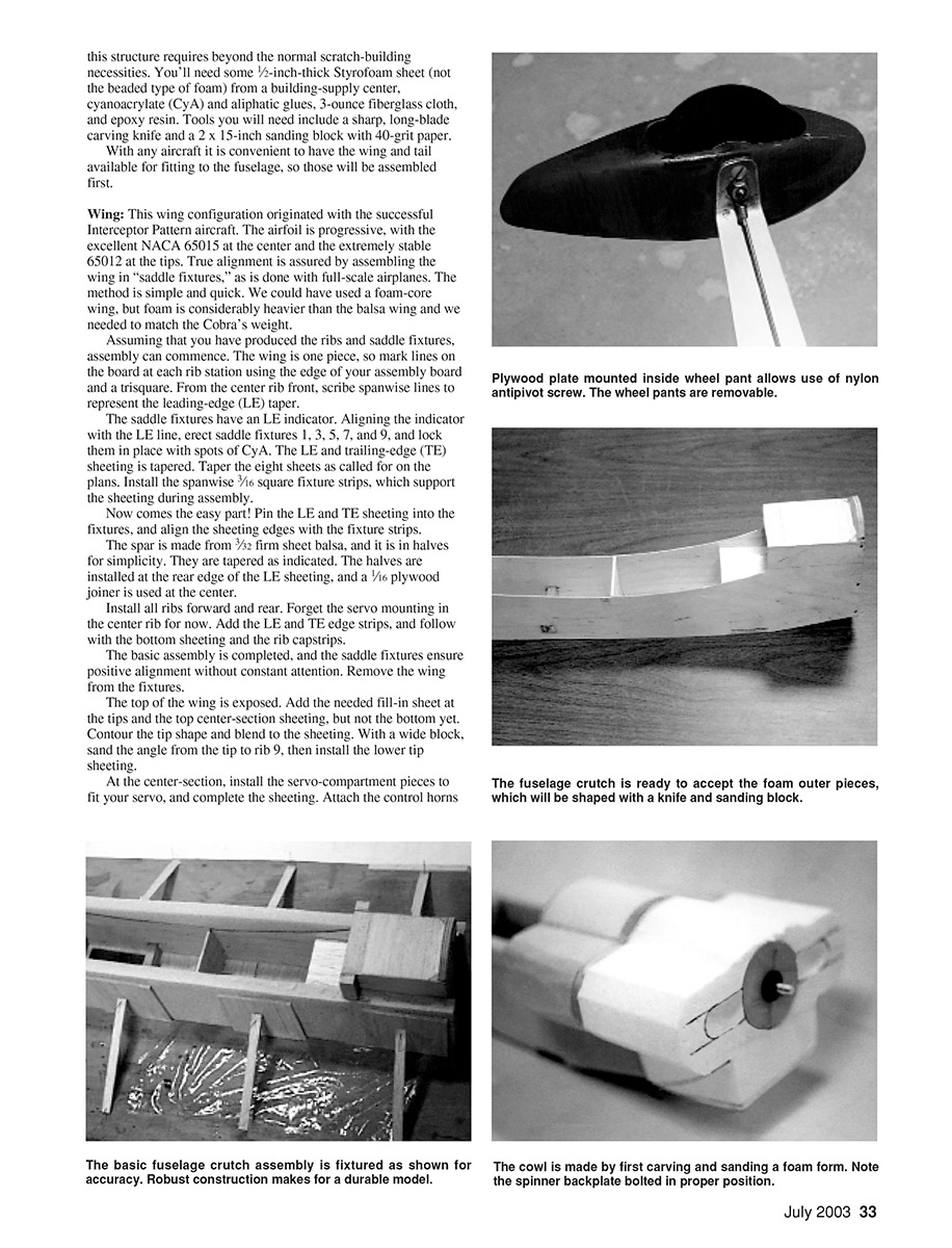
With its futuristic structure, this is where the difference is and perhaps some new lessons will be learned. Understanding the stress factor can assist one's thinking. There is a rectangular plywood "box," and foam is attached to it. All of the major stresses the model encounters are absorbed by this box. The engine, landing gear, wing, and servos are connected to it. In effect, all the foam does is transform the box into the desired shape of the fuselage.
Use only aliphatic glue (Titebond, Elmer's, etc.) for fuselage assembly. The joints will be butt joints in the foam sheeting. When joining the foam, keep the glue away from the outside or the inside edges of the joints because glue seams are a detriment when sanding foam. The joints will be further secured when the covering is attached with epoxy resin.
Produce the plywood parts for the substructure box and assemble it. As there would be with a normal structure, there are two sides of foam. Scribe a long line on the assembly board, and center the substructure on it. Spot-glue with CyA to hold the substructure in place. Cut two sides from foam sheet and glue them to the substructure using the line to assure alignment. Install the two balsa bulkheads between the sides. There is an angled wing-fairing joiner at the wing TE. The wing fairing and fuselage have matching balsa surfaces.
Install the top deck. As indicated, two tapered lengths of foam extend from the joiner to the stabilizer LE. The bottom edges are angled so that they "lean in" a bit. Glue them in place, and flatten their top edges with a sanding block. Glue an appropriate strip of foam to the top edges.
At the joiner position, create the angle and glue the already-shaped balsa surface to the foam. On the top of the substructure at the wing LE, position and glue the balsa former in place.
On the substructure where the wing LE will be attached, use some 1/8-inch balsa sheet to cover the area and shape the top to suit the former.
With the carving knife and long sanding block, and using the joiner-plate shape as a guide, carve and sand the top deck to shape. Place the wing-joiner plate in position, and, as with the rear top deck, fabricate two foam side pieces as indicated. These should have an angle on the lower edge. Glue these front and back to the balsa facings. Block-sand the edges flat and glue an appropriate strip of foam to them.
Fill the area on top of the substructure, in front of the LE position and between the formers, with foam. Glue the properly shaped 1/4-inch balsa former onto the bottom of the engine-mount bulkhead and another to the front of the landing-gear mount. Fill the area between with foam.
The bottom of the fuselage is a long length of foam; leave this off until after the equipment is installed.
Now comes the fun part: producing those pretty flowing lines. There is a slight curvature to the main sides. To begin this shape, work in the lengthwise direction with the long sanding block. Work carefully because the foam comes off easily. With that finished, create the rest of the shape, carving and sanding so that the shapes flow into the curved sides.
When the rough sanding is done, put some sizable pieces of 100-grit sandpaper in the palm of your hand and blend to the various shapes, sanding them to perfection. Note that the airfoil curvature is in the substructure.
Remove the side foam in the mount area and prepare to install the wing. It will be more convenient if the landing gear is installed at this point, so attach it now.
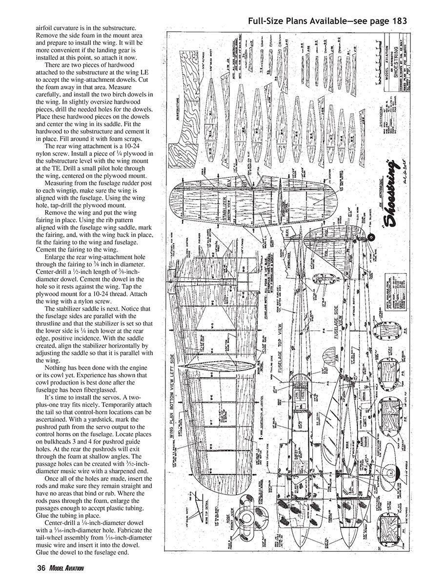
There are two pieces of hardwood attached to the substructure at the wing LE to accept the wing-attachment dowels. Cut the foam away in that area. Measure carefully, and install the two birch dowels in the wing. In slightly oversize hardwood pieces, drill the needed holes for the dowels. Place these hardwood pieces on the dowels and center the wing in its saddle. Fit the hardwood to the substructure and cement it in place. Fill around it with foam scraps.
The rear wing attachment is a 10-24 nylon screw. Install a piece of 1/4-inch plywood in the substructure level with the wing mount at the TE. Drill a small pilot hole through the wing, centered on the plywood mount.
Measuring from the fuselage rudder post to each wingtip, make sure the wing is aligned with the fuselage. Using the wing hole, tap-drill the plywood mount.
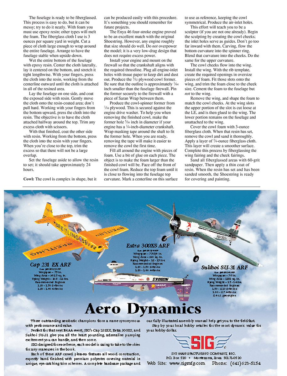
Remove the wing and put the wing fairing in place. Using the rib pattern aligned with the fuselage wing saddle, mark the fairing, and, with the wing back in place, fit the fairing to the wing and fuselage. Cement the fairing to the wing.
Enlarge the rear wing-attachment hole through the fairing to 3/8 inch in diameter. Center-drill a 1/2-inch length of 3/8-inch-diameter dowel. Cement the dowel in the hole so it rests against the wing. Tap the plywood mount for a 10-24 thread. Attach the wing with a nylon screw.
The stabilizer saddle is next. Notice that the fuselage sides are parallel with the thrustline and that the stabilizer is set so that the lower side is 1/4 inch lower at the rear edge, positive incidence. With the saddle created, align the stabilizer horizontally by adjusting the saddle so that it is parallel with the wing.
Nothing has been done with the engine or its cowl yet. Experience has shown that cowl production is best done after the fuselage has been fiberglassed.
It’s time to install the servos. A two-plus-one tray fits nicely. Temporarily attach the tail so that control-horn locations can be ascertained. With a yardstick, mark the pushrod path from the servo output to the control horns on the fuselage. Locate places on bulkheads 3 and 4 for pushrod guide holes. At the rear the pushrods will exit through the foam at shallow angles. The passage holes can be created with 3/32-inch-diameter music wire with a sharpened end.
Once all of the holes are made, insert the rods and make sure they remain straight and have no areas that bind or rub. Where the rods pass through the foam, enlarge the passages enough to accept plastic tubing. Glue the tubing in place.
Center-drill a 1/4-inch-diameter dowel with a 1/16-inch-diameter hole. Fabricate the tail-wheel assembly from 1/16-inch-diameter music wire and insert it into the dowel. Glue the dowel to the fuselage end.
The fuselage is ready to be fiberglassed. This process is easy to do, but it can be messy; try to do it neatly. With foam you must use epoxy resin; other types will melt the foam. The fiberglass cloth I use is 3 ounces per square yard in weight. Cut a piece of cloth large enough to wrap around the entire fuselage. Arrange to have the fuselage stable when upside-down.
Wet the entire bottom of the fuselage with epoxy resin. Center the cloth laterally, lay it centered on the bottom, and stretch it tight lengthwise. With your fingers, press the cloth into the resin, working from the centerline outward until the cloth is attached in all of the resined area.
Lay the fuselage on one side, and coat the exposed side with resin. Gently move the cloth onto the resin-coated area; don't pull hard. Working with your fingers, press the bottom upward, press the cloth into the resin. The objective is to have the cloth attached halfway around the top. Trim any excess cloth with scissors.
With that finished, coat the other side with resin. Working from the bottom, press the cloth into the resin with your fingers. When you're close to the top, trim the excess so that there will not be a large overlap.
Set the fuselage aside to allow the resin to set; it should take approximately 24 hours.
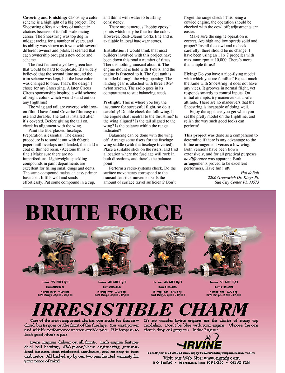
Cowl
The cowl is complex in shape, but it can be produced easily with this procedure. It's something you should remember for future projects.
The Enya 46 four-stroke engine proved to be an excellent match with the original Shoestring. However, any engine roughly that size should do well. Do not overpower the model; it is a very low-drag design that does not require excess power.
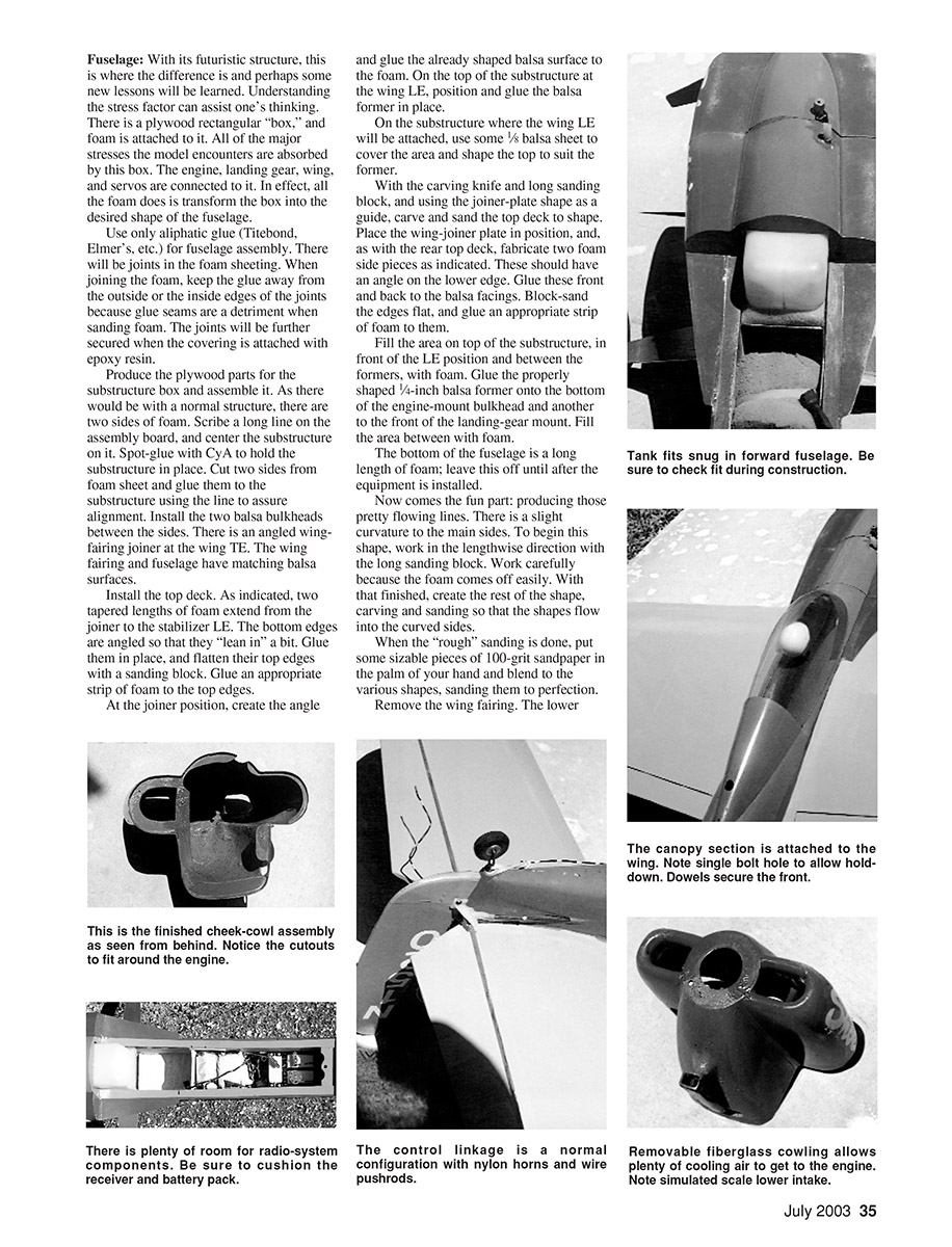
Install your engine and mount on the firewall so that the crankshaft aligns with the required thrustline. Plug all engine-mount holes with tissue paper to keep dirt and dust out. Produce the 3/32-inch plywood cowl former. Be sure that the outline is approximately 1/64 inch smaller than the fuselage firewall. Pin the former securely to the firewall with a piece of Saran Wrap between them.
Produce the cowl-spinner former from 1/16-inch plywood. This is secured against the engine drive washer. To help you when removing the finished cowl, make the former hole 5/16 inch in diameter if your engine has a 1/4-inch-diameter crankshaft. Wrap masking tape around the shaft to fit the former hole. When you are ready, removing the tape will make it easier to remove the cowl the first time.
Fill all around the engine with pieces of foam. Use a bit of glue on each piece. The object is to make the foam larger than the finished cowl will be. Face off the front of the cowl foam. Reduce the top foam until it is close to flowing into the fuselage top curvature. Mark a centerline on this surface to use as reference, keeping the cowl symmetrical. Produce the air-inlet holes.
This effort will teach you to be a sculptor (if you are not one already). Begin the sculpting by creating the cowl cheeks; the inlet holes serve as guides. Don't go too far inward with them. Carving, flow the bottom curvature into the spinner ring. Blend that curvature into the cheeks. Round the upper curvature.
The cowl cheeks flow into the wing. Install the wing. With the rib template, create the required openings in oversize pieces of foam. Fit those slots on the wing, and trim the foam close to the cheek size. Cement the foam to the fuselage but not to the wing.
Remove the wing, and shape the foam to match the cowl cheeks. At the wing slots the upper portion of the slot is loose at the LE, and is then glued to the wing. The lower portion remains on the fuselage and unattached to the wing.
Cover the cowl foam with 3-ounce fiberglass cloth. When that resin has set, remove the cowl and sand it thoroughly. Apply a layer of 1/4-ounce fiberglass cloth. This layer will create a smoother surface. Complete this process by fiberglassing the wing fairing and the cheek fairings.
Sand all fiberglassed areas with 60-grit sandpaper. Then apply a thin coat of resin. When the resin has set and has been sanded smooth, the Shoestring is ready for covering and painting.
Covering and Finishing
Choosing a color scheme is a highlight of a big project. The Shoestring offers a variety of authentic choices because of its full-scale racing career. The Shoestring was top dog in midget racing for a number of years, and its ability was shown as it won with several different owners and pilots. It seemed that each ownership brought a new color and scheme.
The first featured a yellow-green hue that would be hard to duplicate. It's widely believed that the second time around the trim scheme was kept, but the base color was changed to blue. That's the design I chose for my Shoestring. A later Circus Circus sponsorship inspired a wild scheme of bright colors which would stand out on any flightline.
The wing and tail are covered with iron-on film. I have found Coverite film easy to use and durable. The tail is installed after it's covered. Before gluing the tail on, check its alignment with the wing.
Paint the fiberglassed fuselage. Preparation is essential. The easiest procedure is to sand it out with 60-grit paper until overlaps are blended, then add a coat of thinned resin. (Acetone thins it fine.) Make sure there are no imperfections. Lightweight spackling compounds in paint departments are excellent for filling small dings and dents. The same compound makes an easy primer base coat. It fills well and sands effortlessly. Put some compound in a cup, and thin it with water to brushing consistency.
There are numerous "hobby epoxy" paints which may be fine for the color. However, Rust-Oleum works fine and is available in local hardware stores.
Installation
I would think that most builders involved with this project have been down this road a number of times. There is nothing unusual about it. The engine mount is held with T-nuts, and the engine is fastened to it. The fuel tank is installed through the wing opening. The landing gear is attached with three 10-24 nylon screws. The radio goes in its compartment to suit balancing needs.
Preflight
This is where you buy the insurance for successful flight, so do it carefully. Double check the following:
- Is the engine shaft neutral to the thrustline?
- Is the wing aligned?
- Is the tail aligned to the wing?
- Is the balance within the range indicated?
Balancing can be done with the wing off. Arrange some risers for the fuselage wing saddle (with the fuselage inverted). Place a suitable stick on the risers, and find a location where the fuselage will rock in both directions; there's the balance point.
Perform a radio-systems check. Do the surface movements correspond to the transmitter-stick movements? Is the amount of surface travel sufficient? Don't forget the range check. This being a cowled engine, the operation should be checked with the cowl off; adjustments are easier.
Make sure the engine operation is correct. Are high and low speeds solid and proper? Install the cowl and recheck carefully; there should be no change. I have been using an 11 x 7 propeller with maximum rpm at 10,000. There's more than ample thrust.
Flying
Do you have a nice-flying model with which to start a familiar? Expect much the same with Shoestring; it does not have any vices. It grooves in normal flight, yet responds smartly to control inputs. On initial attempts, try maneuvers at a safe altitude. There are no maneuvers that the Shoestring is incapable of doing well.
Enjoy the applause you get when you set the pretty model on the flightline, and relish the way such good looks can perform.
This project was done as a comparison to determine if there is any advantage to the inline arrangement versus a low wing. Both versions have been flown extensively, and for all practical purposes no difference was apparent. Both arrangements proved to be excellent performers. Have fun!
MA
Hal deBolt 2206 Greenwich Dr., Kings Pt. Sun City Center, FL 33573
Transcribed from original scans by AI. Minor OCR errors may remain.

