

Silencer - 2005/03
by Mike Palko
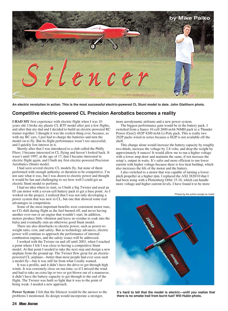
Competitive electric-powered CL Precision Aerobatics becomes a reality
I had my first experience with electric flight when I was 10 years old. I broke my plastic CL RTF model after just a few flights, and after that my dad and I decided to build an electric-powered RC trainer together. I thought it was the coolest thing ever, because, as with my RC cars, I just had to charge the batteries and turn the model on to fly. But its flight performance wasn't too successful, and I quickly lost interest in it.
Shortly after that I was introduced to a club called the Philly Fliers. I became interested in CL flying and haven't looked back. It wasn't until 1997, at the age of 17, that I became interested in electric flight again, and I built my first electric-powered Precision Aerobatics (Stunt) model.
I had seen several electric CL models fly, but none of them performed with enough authority or duration to be competitive. I was drawn to electric power and thought it would be fun and challenging to see how well I could get an electric Stunt model to perform.
I had no idea where to start, so I built a Sig Twister and used an .05 can motor with a seven-cell battery pack to get a base point. As I worked on the project, I realized that I was not only developing a power system that was new to CL, but one that showed some real advantages in competition.
Some of the most important benefits were consistent motor runs, no CG shift during flight as the fuel burned off, and never having another over-run or an engine that wouldn't start. In addition, motors produce little vibration and leave no residue to soak into the balsa and eventually ruin an otherwise good Stunt model.
There are also drawbacks to electric power, such as power-to-weight ratio, cost, and safety. But as technology advances, electric power will continue to approach the performance of internal-combustion engines, and the safety issues will be addressed.
I worked with the Twister on and off until 2003, when I reached a point where I felt I was close to having a competitive Stunt model. At that point I needed to take the next step and design a new airplane from the ground up. The Twister flew great for an electric-powered CL airplane—better than most people had ever seen such a model fly—but it was still far from what I really wanted.
The Twister was a profile model and didn't have the drive to get through high winds. It was extremely close on run time, so if I missed the wind and had to take an extra lap or two or got blown out of a maneuver, it didn't have the battery capacity to get through to the end of the flight. The Twister was built so light that it was to the point of being weak. I needed a new approach.
Power system
I felt that the Silencer would be the answer to the problems I mentioned. Its design would incorporate a stronger, more aerodynamic airframe and a new power system.
The biggest performance gain would be in the battery pack. I switched from a Sanyo 10-cell 2600 mAh NiMH pack to a Thunder Power (Gen2) 4S2P 4200 mAh Li-Poly pack. This is really two 2S2P packs wired in series because a factory 4S2P pack was not available off the shelf. This change alone increased the battery capacity by roughly two-thirds, increased the voltage by about 2.8 volts, and dropped the weight by approximately 8 ounces.
The higher-voltage, higher-capacity pack allowed me to run a higher voltage with a lower amp draw and maintain or increase the setup's output in watts. It's safer and more efficient to run lower current at higher voltage because there is less heat buildup, which also increases the life of the motor and the battery.
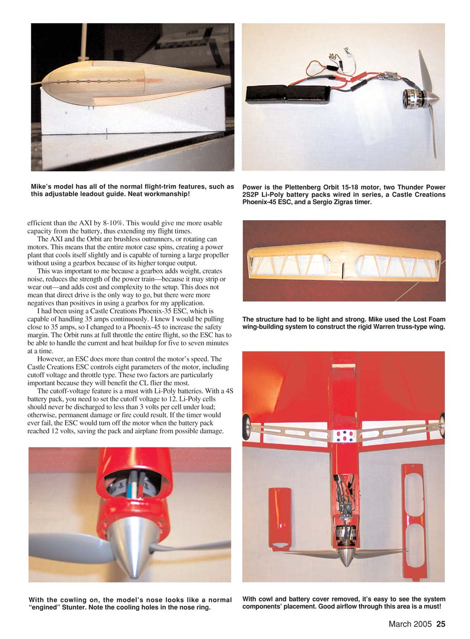
I also switched to a motor capable of turning a lower-pitch propeller at higher rpm. I replaced the AXI 2820/10 with a Plettenberg Orbit 15-18, which can handle more voltage and higher current levels. I found it to be 8–10% more efficient than the AXI. This yielded more usable capacity from the battery and extended flight times.
The AXI and the Orbit are brushless outrunners (rotating-can motors). The entire motor case spins, which slightly improves cooling and provides the torque to turn a large propeller without a gearbox. A gearbox adds weight, noise, complexity, and weak points in the powertrain, so direct drive was preferable for this application.
I had been using a Castle Creations Phoenix-35 ESC (35 A continuous). Knowing I would be pulling close to 35 A, I switched to a Phoenix-45 to increase the safety margin. The Orbit runs at full throttle for the entire flight, so the ESC must handle current and heat buildup for five to seven minutes at a time.
The Castle Creations ESC does more than control motor speed: it controls eight parameters, including cutoff voltage and throttle type. These two features are particularly important for CL fliers.
- Cutoff voltage is a must with Li-Poly batteries. With a 4S battery pack, set the cutoff to 12 volts. Li-Poly cells should never be discharged below 3.0 V per cell under load; otherwise permanent damage or fire could result. If the timer ever fails, the ESC will turn off the motor when the pack reaches 12 V, protecting the pack and airplane.
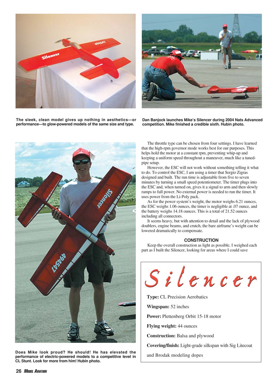
- Throttle type: the high-rpm governor mode works best for our purposes. It helps hold the motor at constant rpm, preventing whip-up and keeping uniform speed throughout a maneuver, much like a tuned-pipe setup.
To control the ESC I used a timer designed and built by Sergio Zigras. The run time is adjustable from five to seven minutes by turning a small speed potentiometer. The timer plugs into the ESC and, when turned on, gives it a signal to arm and then slowly ramps to full power. The timer draws power from the Li-Poly pack—no external power is needed.
Power-system weights:
- Motor: 6.21 ounces
- ESC: 1.06 ounces
- Timer: 0.07 ounce
- Battery: 14.18 ounces
- Total (including connectors): 21.52 ounces
That seems heavy, but with attention to detail and the lack of plywood doublers, engine beams, and crutch, the bare airframe’s weight can be lowered dramatically to compensate.
Construction
Keep overall construction as light as possible. I weighed each part as I built the Silencer, looking for areas where I could save weight. Weight is the biggest concern with electric power because you are "behind" from the start; however, with the right wood selection and a light finish, you can keep the weight to a minimum.
Specs
- Type: CL Precision Aerobatics
- Wingspan: 52 inches
- Wing area: 510 square inches (including flaps)
- Power: Plettenberg Orbit 15-18 motor
- Flying weight: 44 ounces
- Construction: Balsa and plywood
- Covering/finish: Light-grade silkspan with Sig Litecoat and Brodak modeling dopes
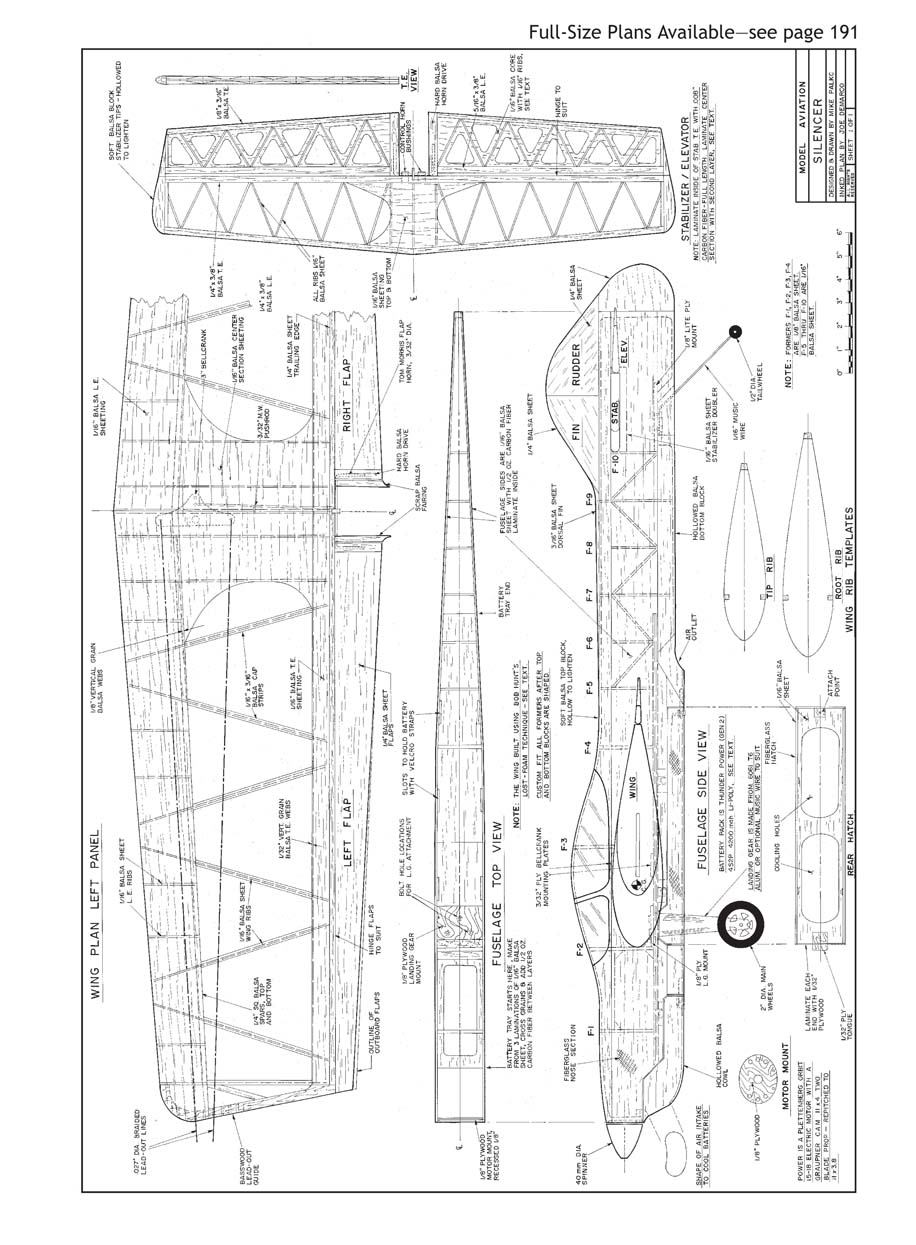
Note: The scanned plans sheet for the Silencer page is a full-size plans sheet and contains only drawing labels and plan notes (no narrative). Examples of the drawing labels include:
- Wing plan left panel
- Left flap / Right flap
- Wing
- Fuselage top view / Fuselage side view
- Stabilizer / Elevator
- Fin / Rudder
- Wing rib templates (tip rib, root rib)
- Rear hatch
- Motor mount
Wing
The wing is built up and utilizes a Warren truss–type ribbing scheme. The main ribs are angled, with half ribs between opposing sets of ribs at the leading edge to support the sheeting. The model has a 52-inch wingspan and 510 square inches of wing area, including the flaps. The wing panels are of equal length.
I built the wing using Bob Hunt's Lost Foam wing-building system because it is one of the most accurate ways to construct a wing. It allows you to build the structure extremely light while maintaining integrity, and it provides the easiest and most accurate way to produce the Warren-truss rib sets.
Using the Lost Foam method, mark the desired rib locations on the front and rear of a foam blank cut to the wing platform. Cut and sand the core, mark the rib locations chordwise using a ballpoint pen, and mark the spar location on the top and bottom. Scribe the rib locations into the lower cradle half from which the core was cut; this cradle is an accurate negative and can be used as a building fixture. Slice the core vertically at each rib station to yield perfectly accurate rib templates for cutting balsa ribs.
Bob Hunt has produced a two-video set about the Lost Foam wing-building system. His company, Robin's View Productions, sells the videos and offers a cutting service and can supply complete Lost Foam fixture sets for this model and others.
To keep weight to a minimum I used 4- to 6-pound contest-grade wood throughout. The flaps are made from 1/4-inch straight C-grain balsa, with the grain following the trailing edge to help reduce warping. The outboard flap is 1/8 inch wider at the tip than the inboard flap to help the inboard and outboard wing panels lift equally in a turn.
The fuselage blankets the outboard wing because the model is flying in a circle and is angled somewhat tangent to the path of flight. Therefore, the outboard wing and flap have less effective area. The outboard flap's larger area helps the wing turn flat and without a rolling tendency, even though there is less airflow over it.
Tailplane
The stabilizer is 3/8 inch thick and is built using Warren truss–style construction. The leading edge and trailing edge are made from 1/4 x 3/8 balsa. I laminated the forward face of the stabilizer trailing edge with 0.008-inch carbon fiber across the full span and used a double layer in the center section for added stiffness. The tips are soft balsa, carved to shape and hollowed.
The elevators are 5/16 inch thick and were built using a sheet of 1/16-inch balsa shimmed 1/8 inch off the building board. The leading and trailing edges were glued to the 1/16 sheet, as were the ribs. I then flipped the elevator over and glued the bottom ribs in place.
I capped the inside root edges of the elevators with hard balsa to support the elevator horn, capped the tips with soft balsa and carved them to shape, then sanded and tapered the elevators to 1/8 inch at the trailing edge. After completion, I removed the wood between each rib to reduce weight further.
Fuselage
The fuselage is built with 1/16-inch C-grain sides. On the inside I doped on 0.5-ounce carbon-fiber mat as a replacement for doublers. The motor mount is 1/8-inch aircraft plywood with three holes drilled and lightly countersunk in each side to allow for motor cooling.
The motor mount sits roughly 1/8 inch behind the front edge of the fuselage. The overhanging fuselage sides act as a small scoop to guide air into the cooling holes. I applied a fillet of Aeropoxy Lite on the inside and outside of the motor mount glue joint for added strength and to help smooth the airflow.
I covered the nose section with 0.75-ounce fiberglass, making sure to wrap around the front of the nose to reinforce the motor-mount joint. I also reinforced the inside motor-mount joint with 0.75-ounce fiberglass.
Final Assembly
Install the battery tray after the wing is joined to the fuselage. Once the wing is in place, its lower center section needs to be removed for battery clearance. During wing construction, the lower bellcrank mount must be sunk into the wing 3/8 inch so you don't sacrifice strength; otherwise this section of the bellcrank mount would be removed to provide clearance for the battery tray.
I made the battery tray from three layers of 1/16-inch balsa with alternating grain to make balsa plywood. I laminated each layer together with epoxy and 0.5-ounce carbon-fiber mat. I epoxied this tray directly to the landing-gear mount, the wing, and the lower bellcrank mount, tying everything together. I used Aeropoxy Lite to make fillets inside the battery compartment and around the wing to help blend and reinforce the joints.
I removed the lower wing center section to position the battery pack as close to the airplane's centerline as possible, to keep the vertical CG in the proper location. If the 14-ounce battery pack had been placed too far from the intended vertical CG, the airplane could rock and roll as speed changes were made during flight or cause the outboard wing to fly high or low in level flight, resulting in poor performance.
Tucking the battery pack high into the fuselage allowed me to have a fuselage with minimal side area. I wanted a model that would fly well in light or heavy winds. Airplanes with large fuselages or vertical surfaces are usually affected more by wind and tend to "weather vane" during flight.
So far this design has proven to work extremely well. Its first real test was at the 2004 Nats, where I flew it in winds exceeding 20 mph, gusting at times to more than 30 mph. This was an extreme case, and in winds that high it's difficult to get any airplane to perform well. The Silencer made it through the wind slowly at times, but I was able to complete the pattern and land it safely.
Flying
The ready-to-fly weight came in at 44 ounces. This gives the Silencer a wing loading of 11.59 ounces per square foot of wing area, which is close to that of glow-powered Stunt models. Performance so far has been better than expected. As of this writing I have put only 25 flights on the Silencer, so I need to do more trim work to get it dialed in, but the potential is surely there.
Propeller selection has been one of the most important trimming areas. First flights yielded lap times in the mid- to low-four-second range with a 10 x 5 APC-E propeller. The model is being flown on 19-strand, .015 x 60-foot, eyelet-to-eyelet control lines.
So far the best propeller for this model has been a Graupner CAM II x 4 two-blade, repitched to 11 x 3.8. On the same 60-foot lines, I am now turning 5.1- to 5.2-second lap times.
At launch the motor pulls 32–34 amps and spins the 11 x 3.8 propeller roughly 11,800 rpm. This equates to approximately 450 watts in (about 0.6 hp) and roughly 382 watts out to the propeller (about 0.51 shp).
After the first flights the battery temperature was 100°F and the motor temperature was 140°F measured at the windings. Motor temperature must be measured at the windings because the motor case spins and cools more than the windings, giving a false reading if measured at the case. Li-Poly batteries should never exceed 140°F during discharge, and brushless motors can handle as much as roughly 200°F safely.
History
- September 7, 2003: I competed in the Bergen County CL contest and finished with 497.5 points, placing eighth out of 17 entrants in Expert with my electric Twister.
- Summer 2004 (AMA Nats): I flew the Silencer to sixth place out of 37 entrants. I also received the James A. Hunt Technical Innovation Award for my accomplishment.
Thanks
This project has turned out to be more fun and rewarding than I ever imagined. I thank Castle Creations and Thunder Power batteries for their fantastic customer service, along with everyone who has helped or supported me throughout this project. Without them it wouldn't be where it is today.
I look forward to future electric-power technology and what it will bring. I will continue developing new electric-powered models and hope you will too.
Mike Palko 121 N. 4th St. Telford, PA 18969 [email protected]
Sources
- Gen2 4S2P 4200 mAh Li-Poly pack: Thunder Power, 4720 W. University Ave., Las Vegas, NV 89103; (702) 228-8883; www.thunderpower-batteries.com
- Plettenberg Orbit 15-18 motor: ICARE, 381 Joseph-Huet, Boucherville, Quebec, J4B 2C5 Canada; (450) 449-9094; www.icare-rc.com
- Phoenix-45 ESC: Castle Creations, 402 E. Pendleton Ave., Wellsville, KS 66092; (785) 883-4519; www.castlecreations.com
- Timer mentioned in text: Sergio Zigras, 171 Arundel Rd., Paramus, NJ 07652
- Lost-Foam wing-building system fixtures and videos: Robin’s View Productions, Box 68, Stockertown, PA 18083; (610) 746-0106
Transcribed from original scans by AI. Minor OCR errors may remain.

