
Simitar Twin
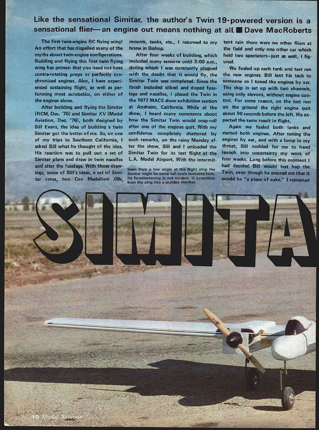
Like the sensational Simitar, the author's Twin 19-powered version is a sensational flier—an engine out means nothing at all. —Dave MacRoberts
The first twin-engine RC flying wing dispelled many myths about twin-engine configurations. Building and flying this twin Simitar proved you need not have contra-rotating props or perfectly synchronized engines. The author experienced sustained flight and was able to perform most aerobatics on either engine alone.
After building and flying the Simitar (RCM, Dec. 1976) and Simitar XV (Model Aviation, Dec. 1976), both designed by Bill Evans, the idea of a twin Simitar took hold. On a trip to Southern California the author asked Bill about the idea. Bill drew twin nacelles and altered the fuselage on a set of Simitar plans. With those drawings, Simitar cores, two Cox Medallion .09s, mounts, tanks, and other parts, the author returned home and completed the Simitar Twin after four weeks of late-night work.
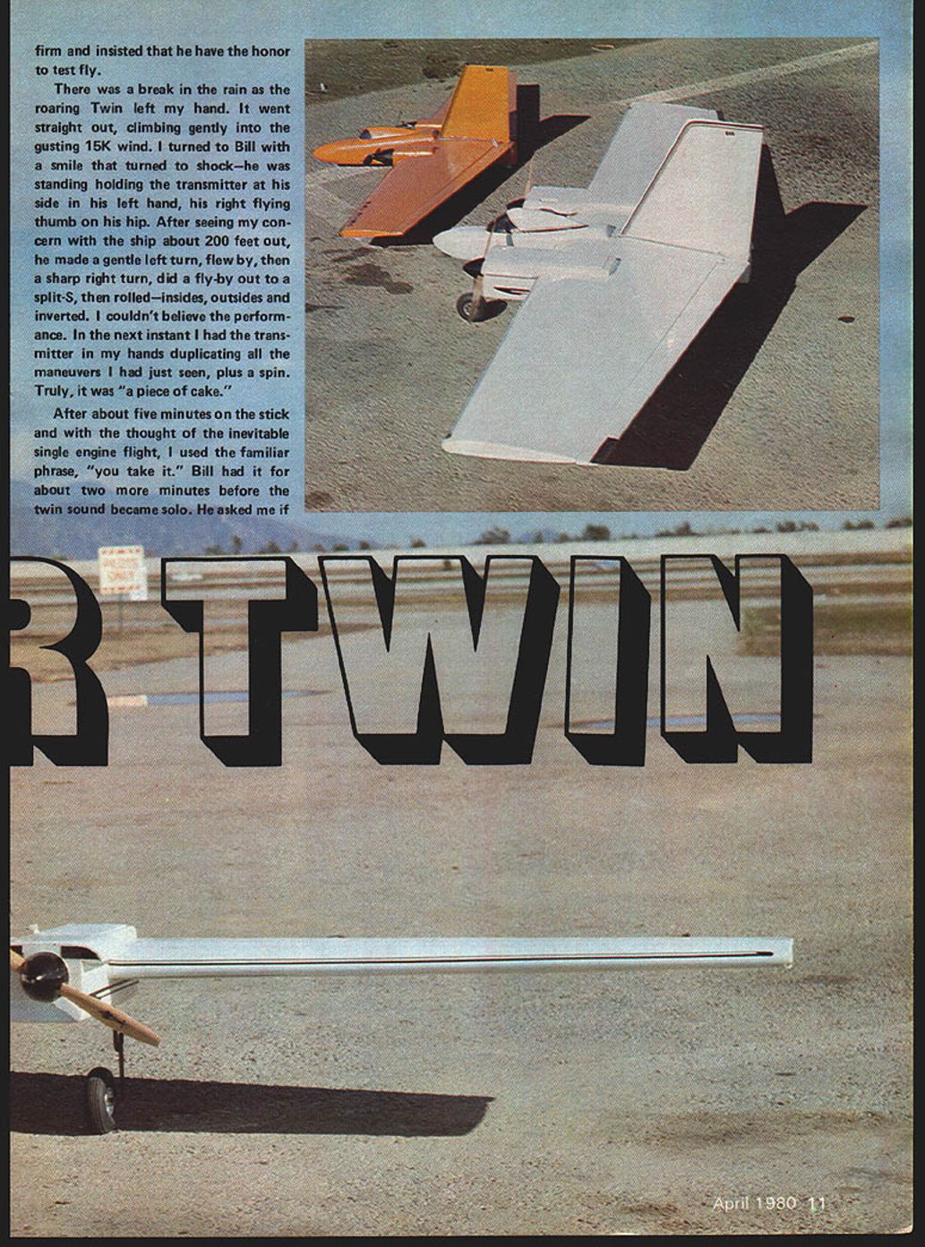
At the 1977 MACS show in Anaheim the finished Twin (silked and doped fuselage and nacelles) drew comments that it would snap-roll if an engine quit. Apprehensive, the author and Bill tested the model at L.A. Model Airport on a rainy day. Both engines were started and tuned by ear. Bill test-flew the Twin and performed gentle and aggressive maneuvers—rolls, split-S, insides and outsides, and inverted flight. The author later took the transmitter and duplicated those maneuvers, plus a spin.
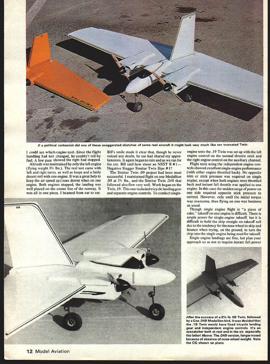
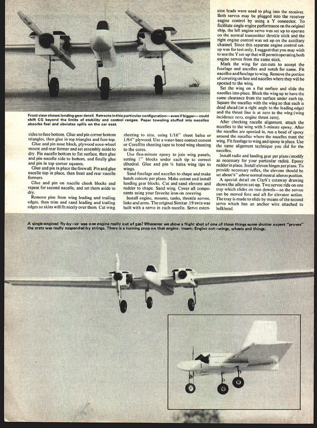
About seven minutes into the flight the Twin became a single-engine ship when the right engine quit. Altitude was maintained on the left engine (flying weight about 3½ lbs.). Turns, loops and a decent roll were performed on one engine; keeping airspeed up (nose down) helped. Both engines later stopped and the landing was well placed on the runway centerline. The airframe was undamaged. Bill jokingly proposed an "NSSTB #1 — Negative Stagger Simitar Twin Bipe #1."
The Simitar Twin .09 project was very successful. Flight was maintained on one Medallion .09 at roughly 3½ lbs. A Simitar Twin .049 also flew well. Work then began on the Twin .19 version, which included tricycle landing gear and separate engine controls. The .19 was set up for single-engine tests with the left engine control on the normal throttle stick and the right engine control on an auxiliary channel.
Flight tests with independent engine controls showed excellent single-engine performance with either engine throttled back. No opposite trim or stick pressure was required on single engine, except when both engines were throttled back and instant full throttle was applied to one engine—then initial torque required opposite stick pressure until the torque was overcome. Takeoff on one engine was difficult due to nose-wheel skipping and bouncing during ground-roll steering. Single-engine landings were fine if the approach was planned to avoid needing instant full power.
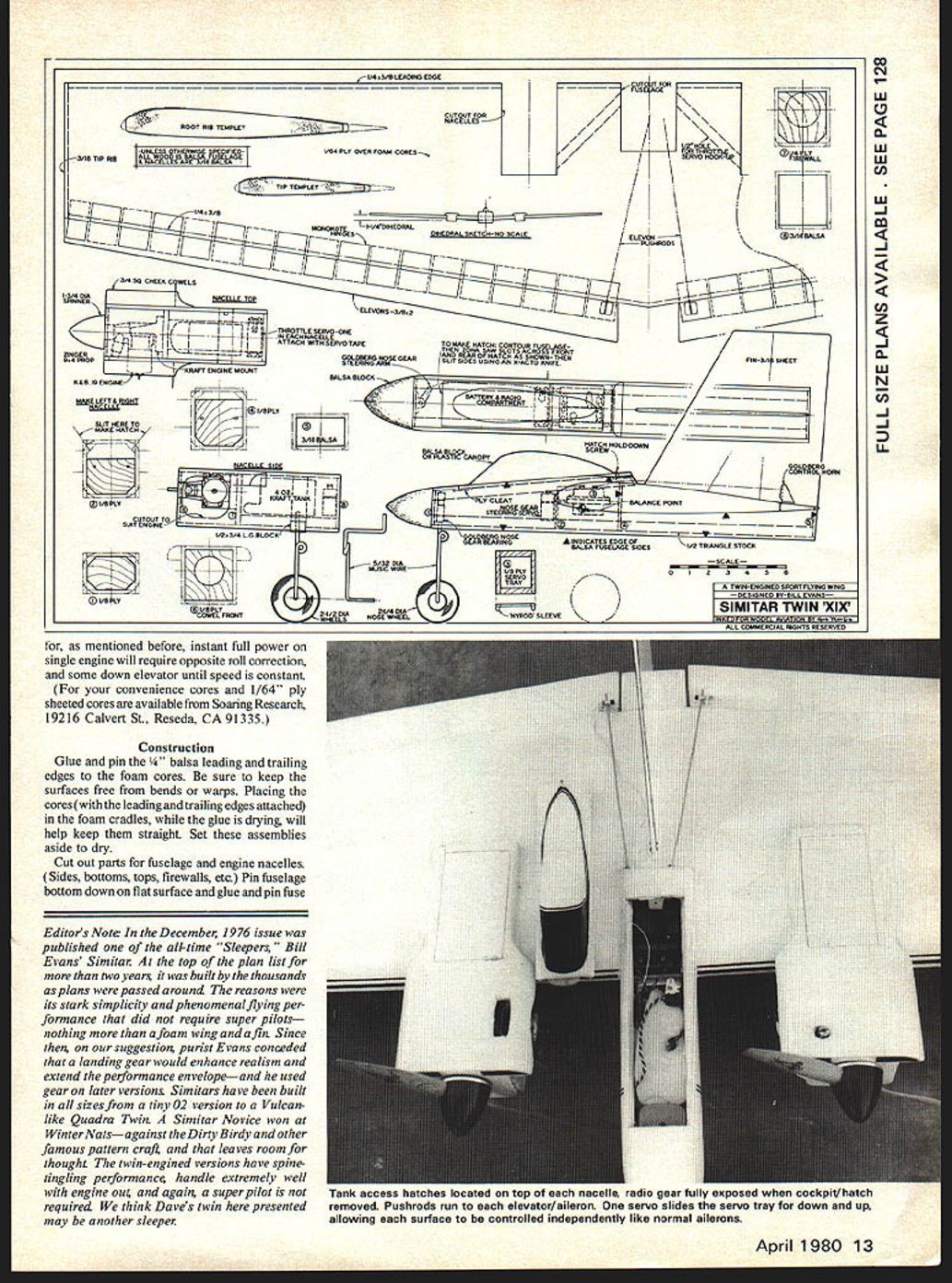
For convenience, cores and 1/64" ply-sheeted cores are available from: Soaring Research 19216 Calvert St. Reseda, CA 91335
Construction
Materials / Parts (selection)
- 1/4" balsa leading and trailing edges
- 1/16" sheet balsa or 1/64" plywood for wing sheeting
- 1/4" x 3/8" spar trailing edge
- 1/4" x 5 1/4" balsa leading edge
- 3/8" x 2" balsa elevons (approx.)
- 3/16" balsa tip rib
- 1/32" plywood planking for wing top and bottom
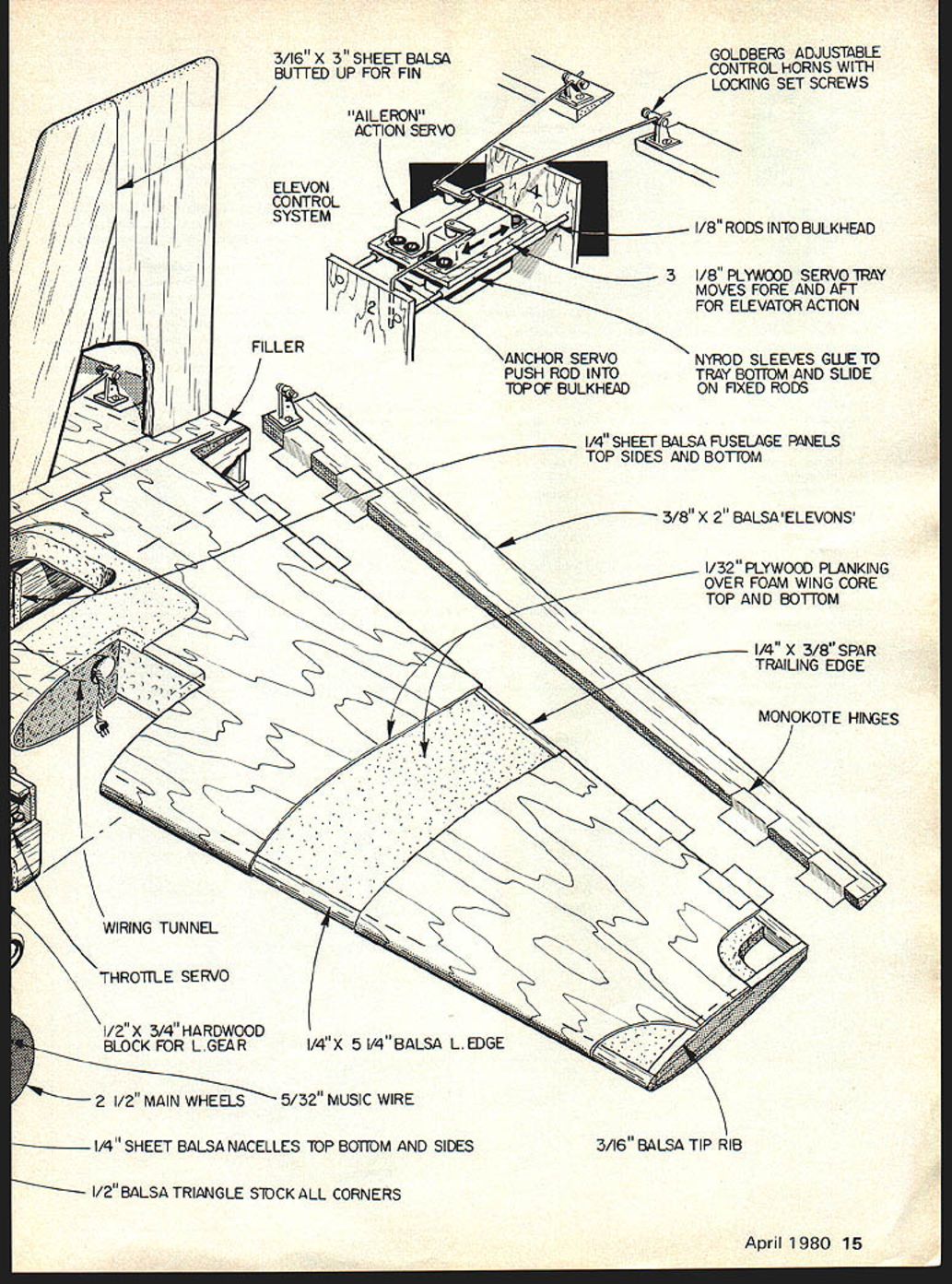
- 1/4" sheet balsa fuselage panels — top, sides and bottom
- 1/4" sheet balsa nacelles — top, bottom and sides
- 1/2" balsa triangle stock for corners
- 1/2" x 3/4" hardwood block for left gear
- 5/32" music wire
- 2-1/2" main wheels
- 1/8" rods into bulkhead
- 1/8" plywood servo tray
- Nyrod sleeves
- Monokote hinges (or equivalent)
- Goldberg adjustable control horns with locking set screws
- 3/16" x 3" sheet balsa (butted up for fin)
- Wiring tunnel, throttle servo, filler
- Servo leads, Y-connector (optional)
- Firewalls, formers, nose-wheel mount, nose block
- Adhesives: water-base contact cement or Corefilm sheeting tape, five-minute epoxy, other glues as needed
- Covering material (iron-on)
Building the Wing Cores
- Glue and pin the 1/4" balsa leading and trailing edges to the foam cores. Keep surfaces free from bends or warps.
- Place the cores (with leading and trailing edges attached) in foam cradles while glue dries to keep them straight. Set assemblies aside to dry.
- Remove pins, then trim and sand the leading and trailing edges so skins will fit nicely.
- Cut wing sheeting to size. Bond sheeting to the cores using a water-base contact cement or Corefilm sheeting tape.
- Use five-minute epoxy to join wing panels. Set 1" blocks under each tip to correct dihedral.
- Glue and pin 1/4" balsa wing tips to wings.
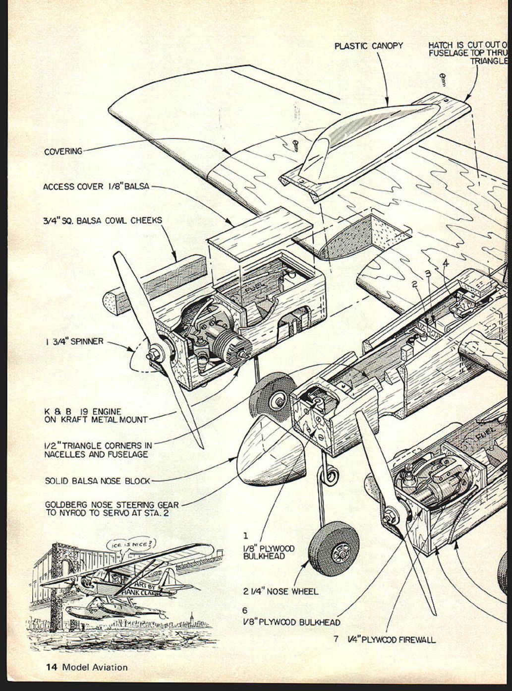
Fuselage and Nacelles
- Cut out fuselage and nacelle parts (sides, bottoms, tops, firewalls, formers, etc.).
- Pin fuselage bottom down on a flat surface and glue and pin fuselage sides to the bottom.
- Glue and pin corner bottom triangles, then glue in top triangles and fuse top.
- Glue and pin nose block, plywood nose-wheel mount and rear former; set assembly aside to dry.
- Pin nacelle bottom to the fuselage surface; glue and pin nacelle side to bottom, then glue and pin in top corner squares.
- Glue and pin in place the firewall. Pin and glue nacelle top in place, then front and rear nacelle formers.
- Glue and pin on nacelle cheek blocks; repeat for second nacelle and set aside to dry.
Finishing the Airframe
- Sand fuselage and nacelles to shape. Make hatch cutouts per plans.
- Make cutout and install landing gear blocks.
- Cut and sand elevons and rudder to shape. Sand wing surfaces.
- Cover all components with your preferred iron-on covering.
Installations and Radio Setup
- Install engines, mounts, tanks, throttle servos, links and servo arms.
- The original Simitar .19 twin was built with a servo in each nacelle and used servo extension leads to the receiver. Both servos may be plugged into the receiver engine control using a Y connector to operate both from one throttle stick.
- For single-engine testing, set the left engine servo on the normal transmitter throttle stick and the right engine on an auxiliary channel (temporary test setup). For normal operation you may prefer the Y setup so one stick controls both engines.
Fitting Wing, Nacelles and Fuselage
- Mark the wing for cut-outs to accept the fuselage and nacelles and notch for fit.
- Fit nacelles and fuselage to wing. Remove the covering where epoxy joints will be made.
- Set the wing on a flat surface and slide nacelles into place. Block the wing so each tip has the same clearance from the work surface.
- Square the nacelles with the wing so each is dead ahead (at right angle to the leading edge) and the thrust line is at zero to the wing (wing incidence zero, engine thrust zero).
- After checking alignment, attach nacelles to the wing with five-minute epoxy. Run a bead of epoxy around the nacelles where they meet the wing.
- Fit fuselage to wing and epoxy in place, using the same alignment technique.
Final Assembly and Controls
- Install radio and landing gear per plans; modify as needed for your radio.
- Epoxy rudder in place. Install elevon hinges per plans.
- To provide necessary reflex, set the elevons about 1/8" above the neutral aileron position.
- Aileron/elevon setup detail (per Clark's cutaway drawing): two servos ride on one tray which slides on two dowels so the servos can be moved fore and aft for elevator action. The tray is made to slide by means of the second servo which has an anchor wire attached to the bulkhead. Anchor the servo push rod into the top of the bulkhead; Nyrod sleeves glue to tray bottom and slide on fixed rods.
- Check all linkages, control horns, and locking set screws. Balance and trim the model as required.
Flight Notes and Tips
- Single-engine flight and most aerobatics are readily achievable on the Simitar Twin.
- Keep airspeed up (nose down) when flying on one engine to maintain control authority.
- Single-engine takeoffs are difficult due to nose-wheel skipping and ground steering problems; although there is ample power, holding the ship straight on the roll is challenging.
- Plan single-engine approaches and avoid situations that require instant full power.
- If you use separate throttle channels for testing, be aware that applying instant full power on one engine while the other is throttled back will require temporary opposite stick input to counter initial torque.
Editor's Note
In December 1976 we published Bill Evans' Simitar, a model that became a "sleeper"—built by thousands for its stark simplicity and phenomenal flying performance that did not require super pilots. Later versions included landing gear for realism and greater performance range. Simitars have been built in many sizes from tiny .02 versions to large multi-engine variants. A Simitar Novice won at Winter Nats—against many famous pattern craft—and twin-engined versions deliver spine-tingling performance while handling extremely well with an engine out. Dave MacRoberts' Simitar Twin may be another sleeper.
Transcribed from original scans by AI. Minor OCR errors may remain.

