
Simple Servo Tester
Peter T. Waters
I HAVE FOUND a servo tester to be one of the handiest gadgets an RC modeler can have on his workbench. It may be used, for example, when installing servos into a new model; one need not use the rest of the airborne pack to set up travel. It is also useful for providing a signal source for servicing servos, and provides a neutral standard to align servos after servicing.
There are several servo testers available on the market and several magazines have published articles on constructing different designs, some extremely complicated. The circuit I have used is outstandingly simple; it uses only seven components in the basic circuit, which practically guarantees that it will work for you. The components are low cost, not critical in size or tolerance, and one can easily add to the basic unit to create a custom unit with features such as meters, deadband check, pre-set neutral limits, and the like. However, this article is aimed at keeping it simple, and modifications are up to the individual.
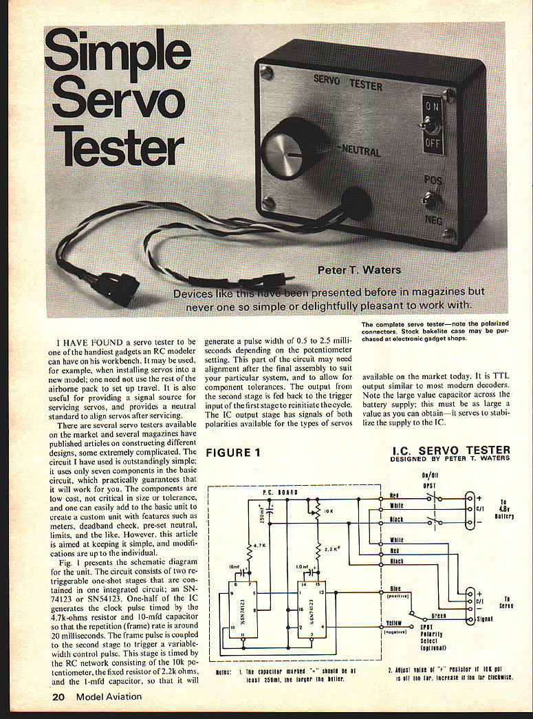
Fig. 1 presents the schematic diagram for the unit. The circuit consists of two retriggerable one-shot stages that are contained in one integrated circuit; an SN74123 or SN54123. One-half of the IC generates the clock pulse timed by the 47k-ohms resistor and 10‑mfd capacitor so that the repetition (frame) rate is around 20 milliseconds. The frame pulse is coupled to the second stage to trigger a variable-width control pulse. This stage is timed by the RC network consisting of the 10k potentiometer, the fixed resistor of 2.2k ohms, and the 1‑mfd capacitor, so that it will generate a pulse width of 0.5 to 2.5 milliseconds depending on the potentiometer setting. This part of the circuit may need alignment after the final assembly to suit your particular system, and to allow for component tolerances. The output from the second stage is fed back to the trigger input of the first stage to reinitiate the cycle. The IC output stage has signals of both polarities available for the types of servos available on the market today. It is TTL output similar to most modern decoders.
Note the large value capacitor across the battery supply. The larger the value you can obtain, the better — it serves to stabilize the supply to the IC.
FIGURE 1
Assembly
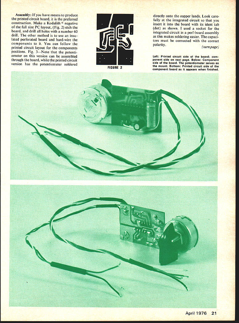
If you have the means to produce a printed circuit board, this is the preferred construction. Make Kodalith (negative) full-size P.C. layout, Fig. 2; etch board, drill holes (No. 60 drill). By other methods, use insulated perforated board and hard-wire the components; you can follow the printed-circuit layout component positions, Fig. 3. Note: the potentiometer version can be assembled through the board. The printed-circuit version has the potentiometer soldered directly onto the copper lands. Look carefully at the integrated circuit insert on the board; its identification tab (dot) shown is used with a socket. Integrated-circuit perf-board assembly makes soldering easier. Capacitors must be connected with correct polarity.
Clean off flux residue from the board using lacquer thinner or dope thinner; a small stiff brush (a toothbrush does nicely). Mop off surplus tissue. Look over soldered connections and touch up as necessary. Make connecting wires about 10 inches long.
The de-luxe version has a Polarity Select switch (double-pole). Some Pro-Line and older EK units, and some older World Engine servos, are known to use a negative pulse. The Polarity Select switch can be eliminated if you do not need to change the polarity of the signal. Install suitable connectors for battery pack and servo output. There are several different types of servos and they need different connectors; either make up adapter cables or wire several servo output lines in parallel. Exercise care handling bare plugs when using the unit. Systems using modern three-wire type amplifiers eliminate the white wire used with the center-tapped supply.
Check over assembly carefully for errors.
Calibration
Smoke-test the finished unit. Set the potentiometer at the middle of its rotation and set the polarity switch appropriately for the servo to be tested. Connect the battery and turn the switch on (with the servo plugged in). Lay a finger on the integrated circuit to detect the IC becoming warm; switch off if it becomes uncomfortably hot.
Assembly:
If you have means to produce the printed circuit board, it is the preferred construction. Make a Kodalith negative of the full-size PC layout (Fig. 2), etch the board, and drill all holes with a number 60 drill. The other method is to use an insulated perforated board and hard-wire the components to it. You can follow the printed circuit layout for the component positions.
Fig. 3 — Note that the potentiometer on this version can be assembled through the board, while the printed-circuit version has the potentiometer soldered directly onto the copper lands. Look carefully at the integrated circuit so that you insert it into the board with its ident tab (dot) as shown. I used a socket for the integrated circuit in a perf-board assembly as this makes soldering easier. The capacitors must be connected with the correct polarity. Switch Off and look over the unit again for possible shorts, orientation of the integrated circuit, battery reversed, and the like.
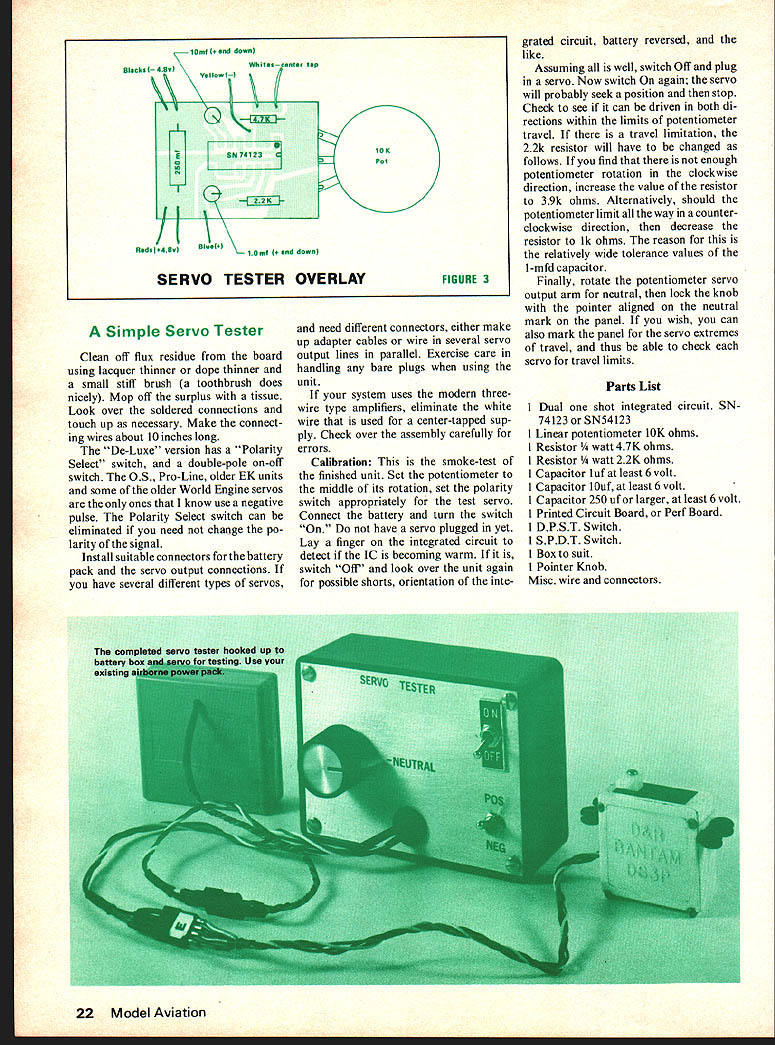
Assuming all is well, switch Off and plug in a servo. Now switch On again; the servo will probably seek a position and then stop. Check to see if it can be driven in both directions within the limits of the potentiometer travel. If there is a travel limitation, the 2.2k resistor will have to be changed as follows. If you find that there is not enough potentiometer rotation in the clockwise direction, increase the value of the resistor to 3.9k ohms. Alternatively, should the potentiometer limit all the way in a counter-clockwise direction, then decrease the resistor to 1k ohms. The reason for this is the relatively wide tolerance values of the 1-mfd capacitor.
Finally, rotate the potentiometer servo output arm for neutral, then lock the knob with the pointer aligned on the neutral mark on the panel. If you wish, you can also mark the panel for the servo extremes of travel, and thus be able to check each servo for travel limits.
Parts List
- 1 Dual one shot integrated circuit. SN74123 or SN54123.
- 1 Linear potentiometer 10K ohms.
- 1 Resistor 1/4 watt 4.7K ohms.
- 1 Resistor 1/4 watt 2.2K ohms.
- 1 Capacitor 1 ufd, at least 6 volt.
- 1 Capacitor 10 ufd, at least 6 volt.
- 1 Capacitor 250 ufd or larger, at least 6 volt.
- 1 Printed Circuit Board, or Perf Board.
- 1 D.P.S.T. Switch.
- 1 S.P.D.T. Switch.
- 1 Box to suit.
- 1 Pointer Knob.
- Misc. wire and connectors.
Transcribed from original scans by AI. Minor OCR errors may remain.

