
Simple Simone
CONTROL LINE (CL) model aviation has been in operation for more than 60 years. However, it is clear that we need to introduce each new generation to it, to replace the growing number of mature fliers who drift away.
Most of the designs published recently are high-performance equipment that require experienced piloting.
Now there are multipurpose clubs, with members from all model-airplane interests. They are proving that we must exist together, rather than separately, in order to increase member numbers on a local basis to acquire and hold flying sites.
These clubs also maintain active training programs to assist beginners through the initial phase, in which an instructor can let the beginner handle the controls and prevent crashing until the novice gets a "feel."
Once the beginner solos, the airplanes must be capable of challenging him or her to become more proficient. The clubs need a good-looking CL training model.
How does one approach a CL design created to be capable of shrugging off the exaggerated control movements made by a beginner who doesn't yet have the feel for the controls and the peculiar operating environment of being in the center of the airplane's flight envelope while maintaining a modest five-second-plus lap time (dizziness factor), and has the ability to plow through blustery 15 mph winds without blowing out of the flight path?
Very carefully!
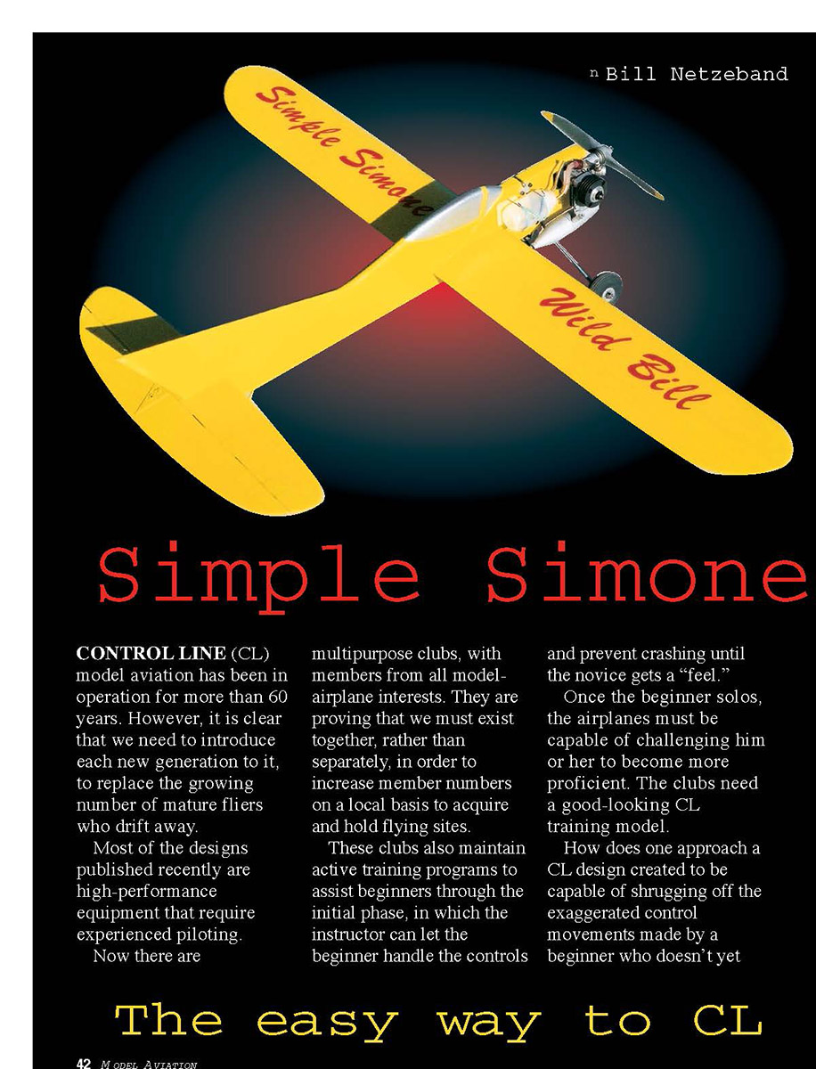
The airplane is scalelike, and has pretty shapes and a canopy, with fairly nice paint.
The geometry utilizes a high (9:1) aspect-ratio wing, with a flat-bottom, cambered section, a generous stabilizer, idealized stabilizer-elevator ratio, and a generous tail-moment arm to help all the parts go in the same direction at the same time.
I originally designed and built Simple Simone in 1956. It provided my St. Louis, MO club with a counterclockwise trainer, with the ability to increase performance.
The original was powered by a Fox .19, and had the J. Roberts throttle system added later. A second airplane was built around the new Fox .15. Both models put in a lot of air time and slow flying for Carrier practice.
A third machine was beefed up to use .36 engines, and did a very nice job of imitating the early Rat Racers. Simple Simone was published in the 1959 Air Trails Annual.
In order to fly CL near Murrieta, CA, we joined a Radio Control (RC) club—the Palomar RC Flyers—because they let us build a CL circle on their field. The main nuisance is a 98 decibels-at-nine-feet noise limit, but we have adapted.
The club works with several youth groups, and we decided to get the CL subgroup ready for youth too. Therefore, Simple Simone was built again.
I made some structural changes to include modern techniques and engines, and ran the aerodynamic characteristics data. The data proved that all of the original geometry features were okay.
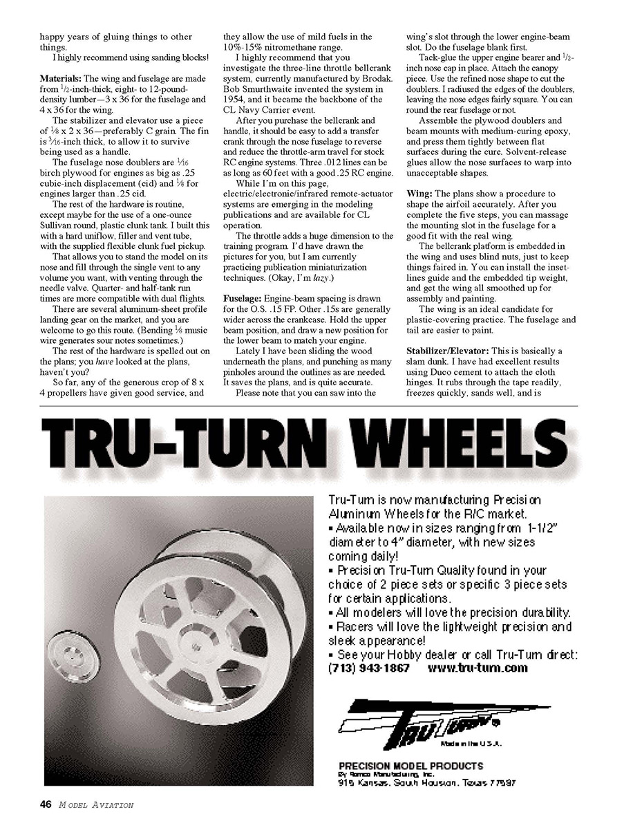
The plans show an O.S. .15 FP and muffler, because it is a good choice, and I have the drawings in my CAD (computer-aided design) system. This airplane is powered by an early Norvel .15, and it is a good match. This is an ideal home for some of those hot .15s that have been outperformed by something hotter.
Construction
Simple Simone wasn't intended to be a beginner's construction project. It requires some woodworking skills, and is happiest when assembled with good glue and alignment skills.
It is a neat idea to have the beginner present during construction, and gently get him or her on the right track with good building techniques.
I'll be brief about the details of construction, and offer a few helpful hints I have learned during these many happy years of gluing things to other things.
I highly recommend using sanding blocks!
Materials
- Wing and fuselage: 1/2-inch-thick, eight- to 12-pound-density lumber—3 x 36 for the fuselage and 4 x 36 for the wing.
- Stabilizer and elevator: 1/8 x 2 x 36—preferably C grain.
- Fin: 3/16-inch thick (to allow it to survive being used as a handle).
- Fuselage nose doublers: 1/16 birch plywood for engines up to .25 cid; 1/8 for engines larger than .25 cid.
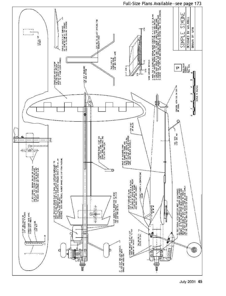
- Tank: one-ounce Sullivan round plastic clunk tank; built with a hard uniflow, filler and vent tube, and the supplied flexible clunk fuel pickup.
That clunk tank allows you to stand the model on its nose and fill through the single vent to any volume you want, with venting through the needle valve. Quarter- and half-tank run times are more compatible with dual flights.
There are several aluminum-sheet profile landing gear on the market, and you are welcome to go this route. (Bending 1/8 music wire generates sour notes sometimes.)
So far, any of the generous crop of 8 x 4 propellers have given good service, and they allow the use of mild fuels in the 10%-15% nitromethane range.
I highly recommend that you investigate the three-line throttle bellcrank system, currently manufactured by Brodak. Bob Smurthwaite invented the system in 1954, and it became the backbone of the CL Navy Carrier event.
After you purchase the bellcrank and handle, it should be easy to add a transfer crank through the nose fuselage to reverse and reduce the throttle-arm travel for stock RC engine systems. Three .012 lines can be as long as 60 feet with a good .25 RC engine.
While I'm on this topic, electric/electronic/infrared remote-actuator systems are emerging in the modeling publications and are available for CL operation.
The throttle adds a huge dimension to the training program.
Fuselage
- Engine-beam spacing is drawn for the O.S. .15 FP. Other .15s are generally wider across the crankcase. Hold the upper beam position, and draw a new position for the lower beam to match your engine.
- I punch pinholes around the outlines by sliding the wood under the plans. It saves the plans and is quite accurate.
- You can saw into the wing's slot through the lower engine-beam slot. Do the fuselage blank first.
- Tack-glue the upper engine bearer and 1/2-inch nose cap in place. Attach the canopy piece. Use the refined nose shape to cut the doublers. I radiused the edges of the doublers, leaving the nose edges fairly square. You can round the rear fuselage or not.
- Assemble the plywood doublers and beam mounts with medium-curing epoxy, and press them tightly between flat surfaces during the cure. Solvent-release glues allow the nose surfaces to warp into unacceptable shapes.
Wing
- The plans show a procedure to shape the airfoil accurately. After you complete the five steps, you can massage the mounting slot in the fuselage for a good fit with the real wing.
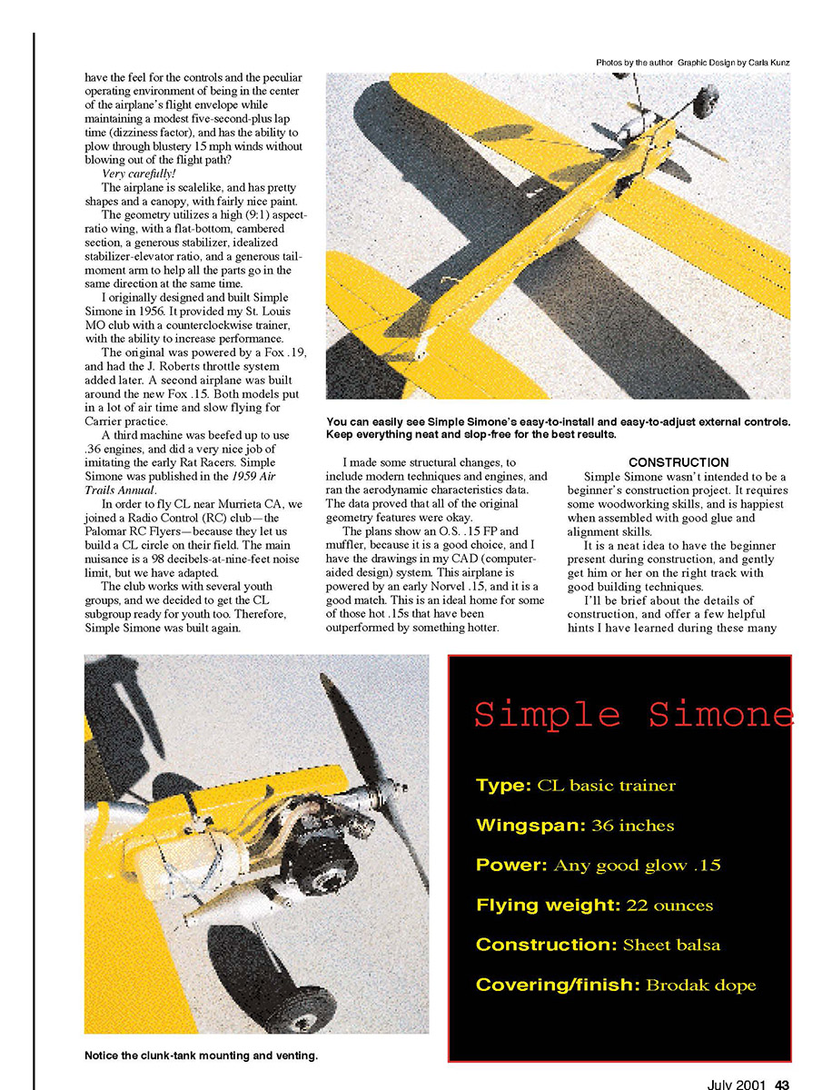
- The bellcrank platform is embedded in the wing and uses blind nuts, just to keep things faired in.
- You can install the inlets guide and the embedded tip weight, and get the wing all smoothed up for assembly and painting.
- The wing is an ideal candidate for plastic-covering practice. The fuselage and tail are easier to paint.
Stabilizer/Elevator
- This is basically a slam dunk.
- I have had excellent results using Duco cement to attach the cloth hinges. It rubs through the tape readily, freezes quickly, sands well, and is compatible with most of the dope and polyurethane finishes I have used.
- The edges of the stabilizer and elevator are shaped to a simple radius, all around, before hinging, and sanded smooth afterwards.
Fin
- There's nothing unusual here. Carve, sand, and glue it onto the fuselage, as straight as your pride will allow.
- The grain runs parallel to the outside edge of the fin.
Hardware
- The landing gear mounting holes, wire tank-mounting bracket holes, and engine-mounting holes are laid out before painting.
- I leave the main landing gear on the bench until after the tailplane has been painted. The same procedure applies to the control hardware.
- Preassemble all of the parts and make their holes in the balsa, then disassemble and paint the model.
- The pushrod length assembly and pushrod guide are basically the best items for permanent assembly by location.
The effect of most built-in CGs is adjusted for with the controls and the trim guide. The prototype model's CG was located 1/2-inch aft of the leading edge. The pushrod was plugged into the holes shown on the plans, and after a few flights the leadout settled through the #3 and #5 holes in the guide.
The final adjustment was a three-inch line set on the handle, and we had a beginner's tune wired in.
All of these items are determined by the interaction of the actual weight, the actual CG, the flight velocity, the actual lines' characteristics, and the actual handle-to-elevator travel ratio.
Simple Simone will do a respectable loop with more elevator action. Please resist the temptation to fly inverted if you insist; give yourself the full height of the circle to recover.
Further performance enhancements come from more power.
You probably already have a training routine. My only caveat: keep the new pilot on dual control until he or she shows signs of correcting the flight path at the turns. See how many solo pilots you can paint on the side of your club's Simple Simone.
Have fun!
SG
Transcribed from original scans by AI. Minor OCR errors may remain.

