
Skinny Scale North American T-28 Trojan
by Gary Fuller
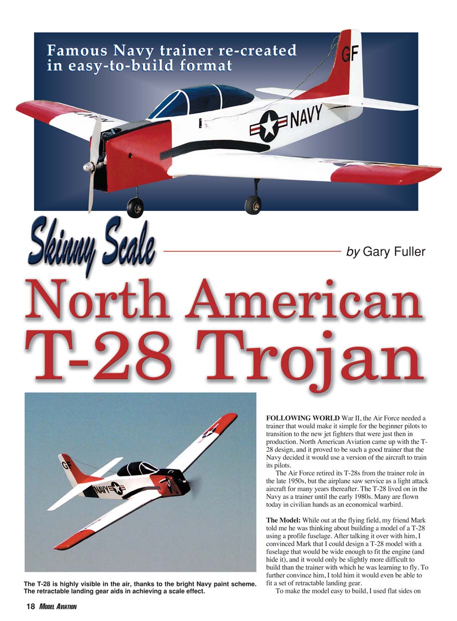
FOLLOWING WORLD War II, the Air Force needed a trainer that would make it simple for beginner pilots to transition to the new jet fighters then entering production. North American Aviation came up with the T-28 design, and it proved to be such a good trainer that the Navy adopted a version of the aircraft to train its pilots.
The Air Force retired its T-28s from the trainer role in the late 1950s, but the airplane saw service as a light-attack aircraft for many years thereafter. The T-28 lived on in the Navy as a trainer until the early 1980s. Many are flown today in civilian hands as economical warbirds.
The Model
While out at the flying field, my friend Mark told me he was thinking about building a model of a T-28 using a profile fuselage. After talking it over, I convinced Mark that I could design a T-28 model with a fuselage wide enough to fit (and hide) the engine, and it would only be slightly more difficult to build than the trainer with which he was learning to fly. To further convince him, I told him it would even be able to fit a set of retractable landing gear.
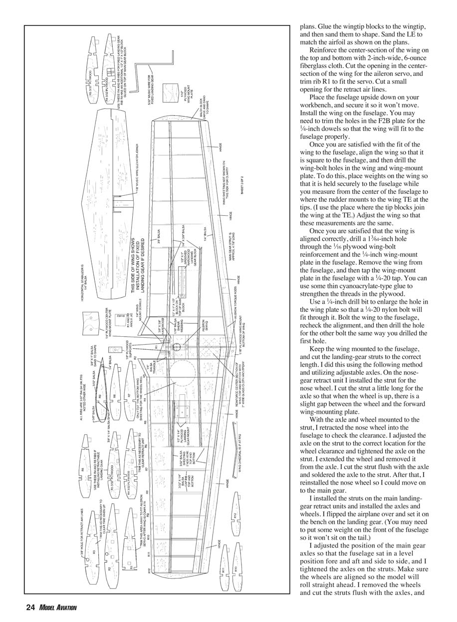
To make the model easy to build, I used flat sides on the fuselage, as are used on a trainer. The top and bottom sheeting is thick, and combined with 1/4-inch balsa triangle stock in the corners, you can almost sand the fuselage to an oval shape. The top sheeting of the fuselage over the engine is cut away to allow easy access to the engine, as in a trainer. To make the T-28 easy to fly, I used a thick semisymmetrical airfoil with a great deal of dihedral, as the full-scale T-28 has. To make the model economical, I designed it with the .40-size engine in mind, which is common in trainers. Therefore you should be able to use the engine that was in your primary trainer. The T-28 should appeal to a wide range of modelers, from those moving up from a trainer to more experienced builders looking for a nice-flying semiscale Sunday flier.
I generally believe that if a full-scale airplane has retractable landing gear, a model of the aircraft won’t look right tooling around with its gear hanging in the breeze; I designed my T-28 with this in mind. But I realize that the expense and trouble associated with retracts don’t appeal to everyone, so the plans show provisions for fixed gear. I tried to design the T-28 with the novice builder in mind, but get help from an experienced builder if you have never built a radio-controlled airplane.
Construction
Fuselage
The fuselage is fairly simple and straightforward. Lay both fuselage sides on your worktable positioned top-to-top. Doing this will keep you from building two left or two right sides.
- Glue the 1/8-inch balsa fuselage doublers to the fuselage sides. Make sure the shorter of the two doublers is glued to the inside of the right fuselage side; this provides 2° of right thrust for the engine.
- Glue the 1/4-inch balsa triangle stock in place on the sides as shown on the plans. Glue the 1/4-inch square balsa to the sides aft of the wing as shown on the plans.
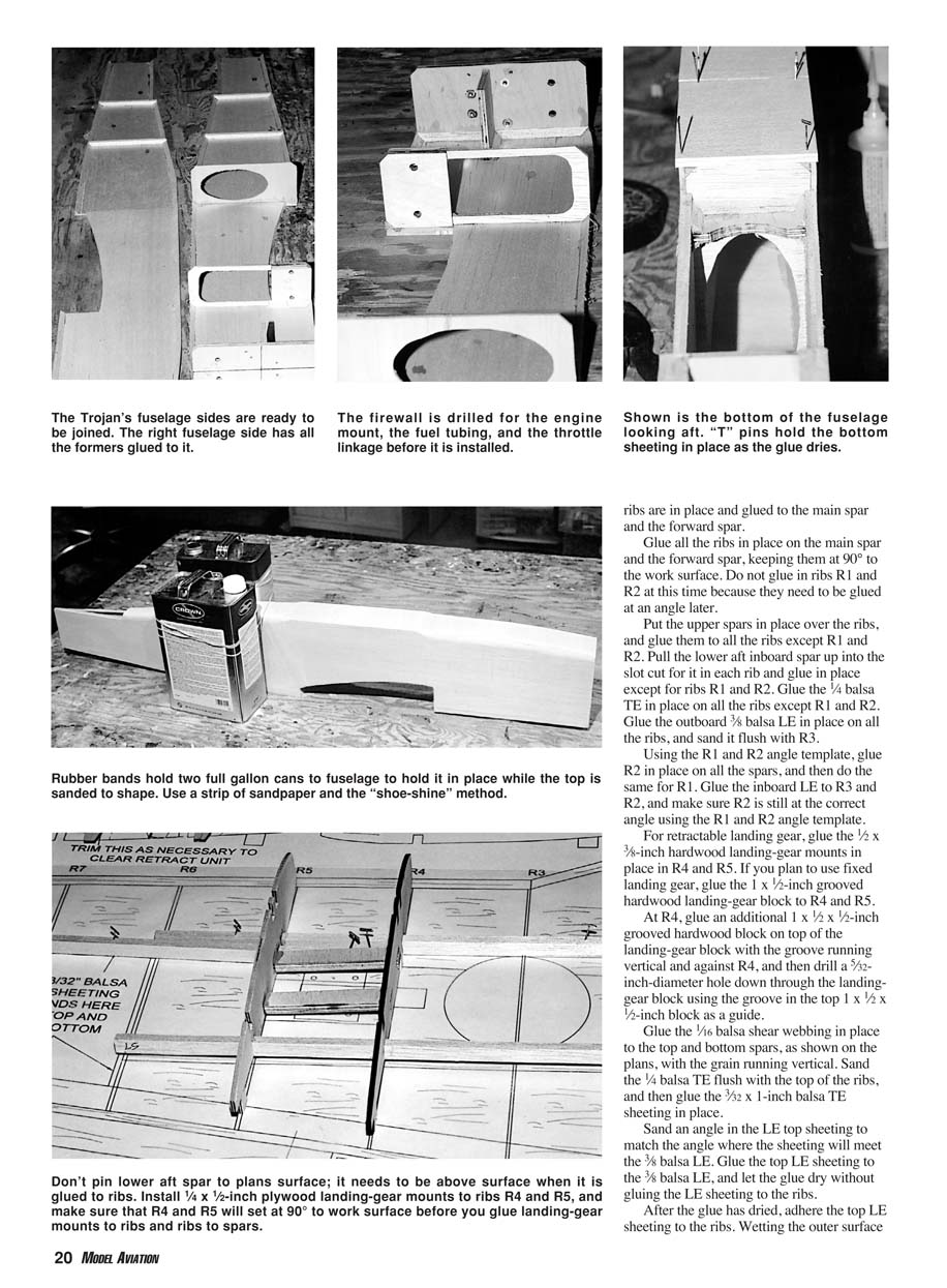
- Drill the holes in F1 for the engine mount, throttle cable, and fuel lines.
- Glue bulkheads F2A, F2B, and F3 in place on the right side only. Ensure the bulkheads are 90° to the side.
- Install the left side to the bulkheads, checking alignment with a carpenter’s square at various places on the top and bottom of the fuselage sides.
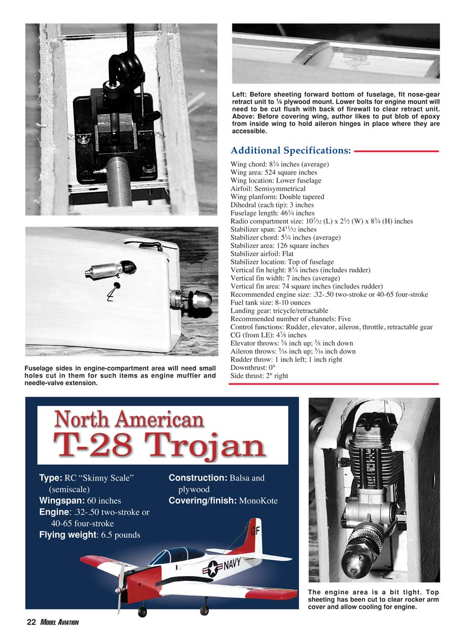
- Install firewall F1. Glue in the 1/4-inch plywood nose-wheel retract mount plate, the 1/16-inch plywood fuel-tank compartment floor, and the 1/4-inch plywood wing-mount plate. Glue the 1/4-inch balsa triangle to F1, F2B, the nose-wheel retract mount plate, and the wing-mount plate as shown on the plans.
If you don't plan to use retractable landing gear, you can skip installing the 1/4-inch plywood nose-gear mounting plate. Use a steerable nose-gear mount attached directly to the firewall or an engine mount that has provisions for mounting a nose-wheel assembly.
Flip the fuselage up on its bottom and join the sides at the tail. You will need to trim the 1/4-inch balsa triangle to do this. Make sure the fuselage is not twisted or crooked as you perform this step.
- Glue on the 3/16-inch balsa top sheeting with the grain running side-to-side.
- Flip the fuselage over and glue the 3/16-inch balsa bottom sheeting to the fuselage aft of the wing with the grain running side-to-side. Do not glue on the bottom sheeting forward of the wing until later.
- Install the nose-wheel retract unit on its mounting plate.
Put the fuselage aside and start the wing.
Wing
The wing is slightly more difficult to build than a trainer's, but it is a fairly straightforward design.
- Cut the 3/8-inch balsa leading edge (LE) from medium to hard balsa. Cut the LE so that it is approximately 3/16 inch wider than each rib's LE; this will be about 1 1/16 inches at R12, tapering to roughly 1 inch at R3. The inboard LE will taper from approximately 1 1/16 inches to 1 inch at R3. You may want to add a bit more to be safe.
- Cut the R1 and R2 rib template from the plans, and glue it to a piece of cardboard or scrap balsa for later use. Use a 3/8-inch-diameter sharpened brass tube to cut the holes in R2 and R3 for the retract air lines.
Start constructing the wing by building one side first:
- Pin the outer lower main spar in place over the plans. Pin the lower forward inboard spar in place over the plans. Place the lower aft inboard spar on the plans but do not pin it; it will be lifted into place after the ribs are glued to the main spar and forward spar.
- Glue all the ribs in place on the main spar and forward spar, keeping them at 90° to the work surface. Do not glue ribs R1 and R2 yet; they need to be glued at an angle later.
- Put the upper spars in place over the ribs, and glue them to all the ribs except R1 and R2.
- Pull the lower aft inboard spar up into the slot cut for it in each rib and glue in place except for ribs R1 and R2.
- Glue the 1/4-inch balsa trailing edge (TE) in place on all the ribs except R1 and R2. Glue the outboard 3/8-inch balsa LE in place on all the ribs and sand it flush with R3.
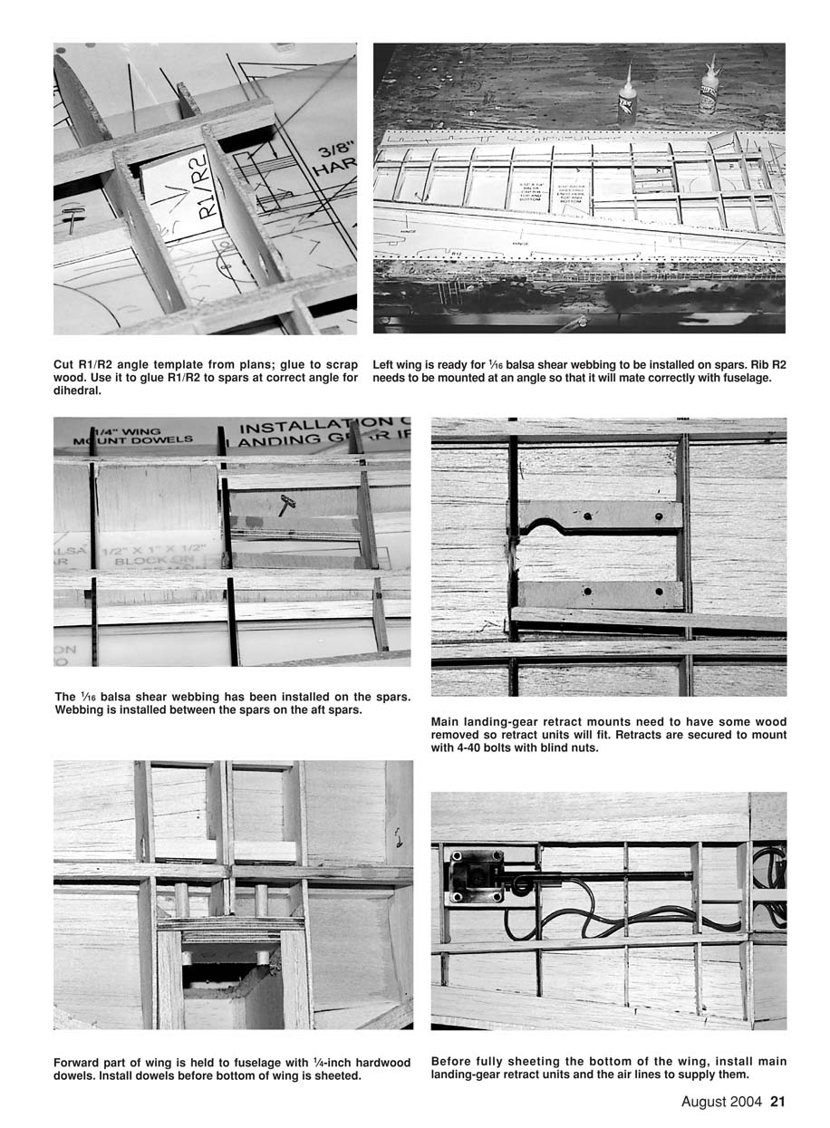
Using the R1/R2 angle template, glue R2 in place on all the spars, then do the same for R1. Glue the inboard LE to R3 and R2, and ensure R2 is still at the correct angle using the template.
- For retractable landing gear, glue the 1/2 x 3/8-inch hardwood landing-gear mounts in place in R4 and R5.
- For fixed landing gear, glue the 1 x 1/2-inch grooved hardwood landing-gear block to R4 and R5.
- At R4, glue an additional 1 x 1/2 x 1/2-inch grooved hardwood block on top of the landing-gear block with the groove running vertical and against R4, then drill a 3/32-inch hole down through the landing-gear block using the groove as a guide.
Glue the 1/16-inch balsa shear webbing in place to the top and bottom spars with the grain running vertical. Sand the 1/4-inch balsa TE flush with the top of the ribs, then glue the 3/32 x 1-inch balsa TE sheeting in place.
- Sand an angle in the LE top sheeting to match where the sheeting will meet the 3/8-inch balsa LE. Glue the top LE sheeting to the 3/8-inch balsa LE and let the glue dry without gluing the LE sheeting to the ribs.
- After the glue has dried, adhere the top LE sheeting to the ribs. Wetting the outer surface of the sheeting with water will help it conform to the ribs. Glue the rest of the top sheeting in place.
- Glue the 1/4 x 3/32-inch balsa rib caps in place.
Unpin this side from the plans, and prop up the wingtip at R12 using a 6-inch-high block that is longer than R12 and has sides that are 6 inches parallel to each other so the wing will not have any twist at the wingtip. Glue the 3/8-inch square hardwood aileron servo mounts to R1 and R2. Build the other wing half the same way, gluing R1 to the other R1 without using the R1/R2 rib template.
Unpin the wing from the building board. Glue the 1/4-inch plywood center wing mount to R1 and R2 as shown on the plans. Fit the wing to the fuselage and drill the holes in the 1/4-inch plywood F2B in the fuselage using the center wing mount as a guide. Remove the wing from the fuselage.
Place 1/4-inch hardwood dowels in the holes to hold the wing to the fuselage. Place 1/8-inch plywood dowel supports on the dowels and glue the supports to the forward inboard top and bottom spars so the 1/4-inch dowels are 90° to the 1/4-inch wing-mount block and parallel to each other. Glue the dowels to the 1/4-inch plywood wing mount and to the 1/8-inch plywood dowel supports.
Begin sheeting the bottom of half the wing by gluing the LE sheeting to the 3/8-inch LE as you did for the top LE sheeting. When the glue has dried, use slow-drying cyanoacrylate to glue the sheeting to the ribs. If you wet the sheeting, place the wing on the building board and weight it down until the sheeting has dried. Prop up the other half of the wing while the sheeting dries. Glue the LE sheeting on the other wing half using the same method.
After the LE sheeting has dried:
- Remove the building tabs from the bottom of the ribs, sand the 1/4-inch TE flush with the ribs, and glue the 1 x 3/32-inch balsa TE sheeting in place.
- Before the rest of the bottom sheeting is installed, fit the main landing-gear retracts in place and run the air lines to the center of the wing. Trim ribs R3 and R4 as necessary to fit the retract units and wheels when the wheels are in the up position.
- Glue the rest of the bottom sheeting in place along with the 1/4 x 3/32-inch rib caps.
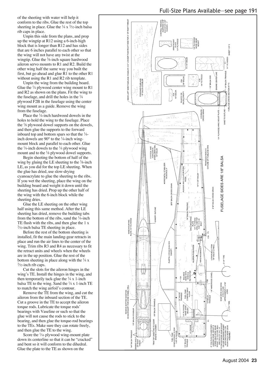
Cut the slots for the aileron hinges in the wing TE. Install the hinges and then temporarily tack-glue the 1/4 x 1-inch balsa TE to the wing. Sand the 1/4 x 1-inch TE to match the wing airfoil contour.
Remove the TE from the wing and cut the aileron from the inboard section of the TE. Cut a groove in the TE to accept the aileron torque rods. Lubricate the torque-rod bearings with Vaseline or similar so the glue will not cause the rods to stick to the bearings, then glue the torque-rod bearings to the TEs. Make sure they rotate freely, then glue the TE to the wing.
Score the 1/16-inch plywood wing-mount plate down its centerline so it can be "cracked" and bent to conform to the dihedral. Glue the plate to the TE as shown on the plans. Glue the wingtip blocks to the wingtips and sand them to shape. Sand the LE to match the airfoil as shown on the plans.
Reinforce the center-section of the wing on the top and bottom with 2-inch-wide, 6-ounce fiberglass cloth. Cut the opening in the center-section of the wing for the aileron servo and trim rib R1 to fit the servo. Cut a small opening for the retract air lines.
Place the fuselage upside down on your workbench and secure it. Install the wing on the fuselage. You may need to trim the holes in the F2B plate so the wing fits properly.
Once satisfied with the fit, align the wing square to the fuselage and drill the wing-bolt holes in the wing and wing-mount plate. Place weights on the wing so it is held securely while you measure from the center of the fuselage to where the rudder mounts to the wing TE at the tips. Adjust the wing so these measurements are the same.
When aligned correctly:
- Drill a 13/64-inch hole through the 1/16-inch plywood wing-bolt reinforcement and the 1/4-inch wing-mount plate in the fuselage. Remove the wing, then tap the wing-mount plate in the fuselage with a 1/4-20 tap. Use a little thin cyanoacrylate to strengthen the threads in the plywood if desired.
- Enlarge the hole in the wing plate to accept a 1/4-20 nylon bolt. Bolt the wing to the fuselage, recheck alignment, and then drill the hole for the other bolt the same way.
Keep the wing mounted to the fuselage and cut the landing-gear struts to the correct length. The author used adjustable axles:
- On the nose-gear retract unit, install the strut and cut it a little long for the axle so when the wheel is up there is a slight gap between the wheel and the forward wing-mounting plate.
- Mount the axle and wheel to the strut, retract the nose wheel into the fuselage to check clearance, adjust the axle position for correct clearance, tighten, extend the wheel and remove it from the axle, cut the strut flush with the axle and solder the axle to the strut, then reinstall the nose wheel.
For the main gear:
- Install struts on the main landing-gear retract units, install axles and wheels, flip the airplane and set it on the bench on the landing gear. You may need to add weight to the front of the fuselage so it won't sit on the tail.
- Adjust the position of the main gear axles so the fuselage sits level fore-and-aft and side-to-side. Make sure the wheels are aligned for straight tracking. Remove the wheels, cut the struts flush with the axles, and solder the axles to the struts.
Now is a good time to glue the 1/8-inch balsa belly pan sides to the wing along with bulkhead F3A and the 3/16-inch belly pan bottom sheeting.
Remove the wing from the fuselage and cut the bottom sheeting for the main wheels to retract into. Mount the wheels to the axles and actuate the retract unit by hand so the main wheel lies against the sheeting. Mark the sheeting around the wheel and strut, move the wheels to the down position, and cut the sheeting at the marks. Move the wheel to the up position and trim the hole and ribs R3 and R4 so the wheel and strut fit into the wing. Leave roughly 1/8 inch of clearance around the wheel and strut to allow for bent struts on rough landings. If you wish, line the openings with 1/16-inch balsa (not shown on plans).
Sheet the bottom of the forward fuselage and cut the bottom sheeting for the nosewheel opening as you did for the main wheels.
Tail and Final Assembly
- Glue all pieces together for the vertical stabilizer. Hinge the rudder to the vertical stabilizer, but do not glue the hinges permanently yet.
- Hinge the elevators to the horizontal stabilizer, but don't glue those hinges either.
- Glue the piece that separates the elevators to the horizontal stabilizer.
- Cut a groove in the bottom center of the horizontal stabilizer for the music-wire elevator joiner. Mark the elevators for the joiner location, drill the holes and cut grooves in each elevator. Remove the elevators and the rudder and set them aside.
Refit the wing to the fuselage and mount the horizontal and vertical stabilizers:
- Place the fuselage right side up and secure it. Adjust the fuselage position so the wing sits level fore-and-aft by measuring the center of the wing LE and the wing TE to the workbench; they should be the same distance.
- Pin the horizontal stabilizer in place on the back of the fuselage. Sight down the fuselage carefully to ensure the stabilizer is not tipped to one side. Sand the high side of the stabilizer mounting area if necessary.
- Measure from the LE and TE of the stabilizer to the workbench; these need to be the same so the incidence angle between stabilizer and wing is 0°. Double-check lateral alignment by measuring from wing TE tip to stabilizer TE tip on both sides; adjust until equal. When satisfied, glue the horizontal stabilizer in place, making sure the elevator joiner is installed in the stabilizer center.
- Pin the vertical stabilizer in place, sight along the fuselage to align it with the centerline, and glue it so it is 90° to the horizontal stabilizer.
Finish
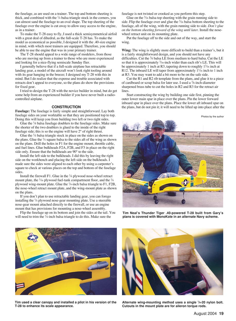
Most of the airplane is finished now; what remains are finishing touches and radio installation. If you plan to use a plastic canopy, mount it after you cover the fuselage. If you plan to carve and sand a balsa-block canopy, you may mount it before covering; hollowing the balsa canopy provides an ideal place to mount the retract air tank.
- Finish-sand the T-28 to the cross-sections shown on the plans. Bevel the hinged parts of the control surfaces while finish-sanding. The more time you spend here, the better the model will look.
- Temporarily mount the rudder, elevators, and ailerons, then mount the servos and build up the pushrods. Do the same for the engine. Run the nose-wheel steering cable to the nose-wheel retract unit, hook it up, and adjust for smooth operation.
- I recommend pneumatic retracts and routing the air lines for the main gear through the wing before you cover it. Decide where to mount the retract air tank: under a non-clear canopy, mount the tank under the canopy; with a clear canopy and cockpit dressing, mount the tank behind the wing on the bottom sheeting inside the fuselage. Glue the tank to the bottom sheeting using RTV and make sure it doesn't interfere with the elevator and rudder pushrods.
- Cover the model with MonoKote or your preferred covering. Once covered, cut away the covering where the canopy belongs and dress up the cockpit. Glue the canopy to the fuselage using formula 560-type glue; cyanoacrylate may permanently fog the canopy.
- Permanently mount the control surfaces, hook up servos, and check directions and throws.
- Install the engine and fuel tank. Install the retract air valve and retract servo in convenient locations. Install the radio on/off switch and the retract air fill valve on the side opposite the engine exhaust. Install the receiver but hold off on installing the battery so you can move it to adjust CG.
- Assemble the wing to the fuselage, check the balance point, and place the battery where needed to achieve the correct CG. The author placed the battery as far forward as possible and still needed to add nose weight.
- Remove the wing, install the battery, reassemble, pressurize the retract air system, and check retract operation and for air leaks. Check the wing for warps and correct any found.
Flying
My first flight with the T-28 was a near disaster. The O.S. 40 four-stroke wasn't producing full power because of a bad glow plug, but I didn't realize that until I rotated and the T-28 staggered into the air and barely climbed higher than about 10 feet.
After getting roughly 200 feet away from the runway, I chopped the throttle and landed in a bean field north of the runway. The one good thing from the short flight was that the airplane seemed to have excellent low-speed handling. When I retrieved it, I found it had sustained no damage. After changing the glow plug and readjusting the high-speed needle, the next flight went much better.
Once at a safe altitude, I confirmed the slow-speed handling was very good. It will slow down considerably before it starts to wallow and then stall and drop a wing. Despite the small chord of the ailerons, the roll rate is respectable and the ailerons feel solid.
Vertical performance with the O.S. 40 four-stroke is not spectacular but is more than adequate for scalelike flight. Landings are a breeze: as it nears the runway, hold the airplane off with up-elevator as you bleed off airspeed and you will be rewarded with a beautiful touchdown on the mains. On pavement you can hold the nose wheel off the runway until the T-28 is nearly stopped.
This has turned out to be a thoroughly enjoyable airplane. The simple construction technique, pleasant flight characteristics, and semiscale looks have given me many hours of satisfaction. If you are a beginner or an advanced flier looking for something simple to build that doesn't look like the ordinary model, this may be the airplane for you.
Gary Fuller 7076 E. Heather Dr. Claremore, OK 74019 [email protected]
Additional Specifications
- Wing chord: 8 3/4 inches (average)
- Wing area: 524 square inches
- Wing location: Lower fuselage
- Airfoil: Semisymmetrical
- Wing planform: Double tapered
- Dihedral (each tip): 3 inches
- Fuselage length: 46 1/4 inches
- Radio compartment size: 10 7/32 (L) x 2 1/2 (W) x 8 3/4 (H) inches
- Stabilizer span: 24 1/2 inches
- Stabilizer chord: 5 1/4 inches (average)
- Stabilizer area: 126 square inches
- Stabilizer airfoil: Flat
- Stabilizer location: Top of fuselage
- Vertical fin height: 8 3/4 inches (includes rudder)
- Vertical fin width: 7 inches (average)
- Vertical fin area: 74 square inches (includes rudder)
- Recommended engine size: .32–.50 two-stroke or 40–65 four-stroke
- Fuel tank size: 8–10 ounces
- Landing gear: Tricycle/retractable (plans show fixed-gear provisions)
- Recommended number of channels: Five
- Control functions: Rudder, elevator, aileron, throttle, retractable gear
- CG (from LE): 4 7/8 inches
- Elevator throws: 5/8 inch up; 5/8 inch down
- Aileron throws: 5/16 inch up; 5/16 inch down
- Rudder throw: 1 inch left; 1 inch right
- Downthrust: 0°
- Side thrust: 2° right
North American T-28 Trojan
- Type: RC "Skinny Scale" (semiscale)
- Wingspan: 60 inches
- Engine: .32–.50 two-stroke or 40–65 four-stroke
- Flying weight: 6.5 pounds
- Construction: Balsa and plywood
- Covering/finish: MonoKote
Transcribed from original scans by AI. Minor OCR errors may remain.

