
Skinny Scale World War II Val
BY GARY FULLER
Introduction
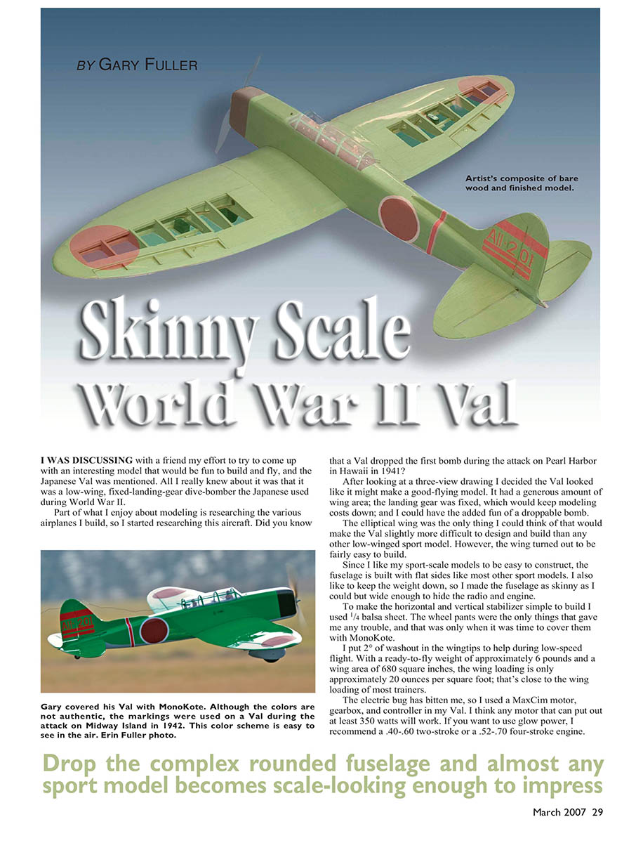
I was discussing with a friend my effort to come up with an interesting model that would be fun to build and fly, and the Japanese Val was mentioned. All I really knew about it was that it was a low-wing, fixed-landing-gear dive-bomber the Japanese used during World War II.
Part of what I enjoy about modeling is researching the various airplanes I build, so I started researching this aircraft. Did you know that a Val dropped the first bomb during the attack on Pearl Harbor in 1941?
After looking at a three-view drawing I decided the Val looked like it might make a good-flying model. It had a generous amount of wing area; the landing gear was fixed, which would keep modeling costs down; and I could have the added fun of a droppable bomb. The elliptical wing was the only thing I could think of that would make the Val slightly more difficult to design and build than any other low-winged sport model. However, the wing turned out to be fairly easy to build.
Since I like my sport-scale models to be easy to construct, the fuselage is built with flat sides like most other sport models. I also like to keep the weight down, so I made the fuselage as skinny as I could but wide enough to hide the radio and engine. To make the horizontal and vertical stabilizer simple to build I used 1/4" balsa sheet. The wheel pants were the only things that gave me any trouble, and that was only when it was time to cover them with MonoKote.
I put 2° of washout in the wingtips to help during low-speed flight. With a ready-to-fly weight of approximately 6 lb and a wing area of 680 in², the wing loading is only approximately 20 oz/ft²—close to the wing loading of most trainers.
The electric bug has bitten me, so I used a MaxCim motor, gearbox, and controller in my Val. I think any motor that can put out at least 350 W will work. If you want to use glow power, I recommend a .40–.60 two-stroke or a .52–.70 four-stroke engine.
Specifications
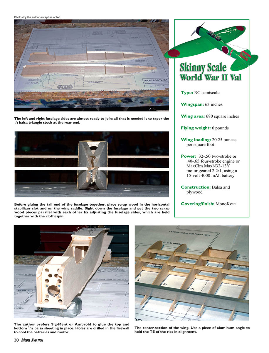
- Type: RC semiscale
- Wingspan: 63 in
- Wing area: 680 in²
- Flying weight: ≈ 6 lb
- Wing loading: 20.25 oz/ft²
- Power: .32–.50 two-stroke or .40–.65 four-stroke engine, or MaxCim MaxN32-13Y motor geared 2.2:1 using a 15 V 4000 mAh battery (approx. 350 W+)
- Construction: Balsa and plywood
- Covering/finish: MonoKote
Photos by the author except as noted.
Construction
Preparing parts
- Cut most parts before building. My favorite transfer method is to cut the plans for each part and adhere the paper directly to the wood with low-tack glue (Elmer's glue sticks work well).
- Use a band saw to rough-cut parts, then remove the paper. Drill firewall motor-mount holes while cutting the firewall.
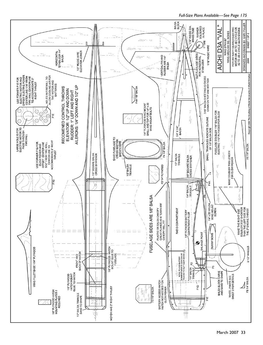
Fuselage
- Lay left and right fuselage sides top-to-top on the bench so you don't make two lefts or rights as you add pieces.
- Glue 1/16" balsa (or plywood if using glow) doublers to the sides. Glue the shorter of the two doublers to the right side—this is for the 2° right thrust for the engine.
- Adhere 1/2" balsa triangle stock to the side edges as shown on the plans. After glue dries, taper the triangle stock at the rear.
- Glue 1/4" square balsa side stiffeners to the sides (per plans).
- Glue formers F2, F3, and F4 to only one side initially. Position F2 to suit glow or electric installation; ensure formers are square (90°) to the side.
- Glue 1/8" square balsa to F4 as shown on the plans. Join the other side by rubber-banding sides together, aligning with a square and eye, and glue the remaining formers and firewall in place.
- Set the fuselage on its top. Place 1/4" balsa scraps in the wing saddle and horizontal stabilizer slots. Bring the aft ends together and hold with a clothespin. Sight down the fuselage and align the scraps parallel; adjust sides until fuselage is straight. Glue the back end together.
- Sheet the top of the fuselage with 3/16" balsa. If using electric power, build a hatch on the top forward part of the fuselage. Sheet the bottom of the fuselage aft of the wing with 3/16" balsa (grain crosswise on top and bottom sheeting).
- The bottom forward of the wing will be sheeted after mounting the wing. Glue in the 1/4" plywood wing-mount plate and allow glue to dry.
- When dry, final-sand the fuselage to shape. I support a plywood backing in a C-clamp and pull sandpaper across the overhanging fuselage to shape it.
Notes:
- Before gluing the tail end together, place scrap wood in the stabilizer slot and on the wing saddle; adjust sides so the scrap pieces are parallel, ensuring a straight fuselage.
- I prefer Sig-Ment or Ambroid to glue top and bottom 3/16" balsa sheeting in place.
- Drill holes in the firewall to cool batteries and motor if using electric.
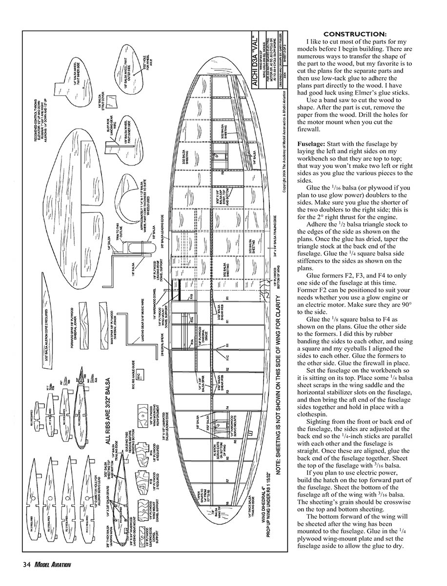
Wing — center-section
- Glue R1A and R1B ribs to the R1 ribs per plans. Pin the forward spar to the bench. Place the rear spar on the plans but do not pin it; it must be lifted into the ribs later.
- Fit (but don't glue) the 1/4" plywood wing dowel support to the ribs that have R1Bs glued and glue them to the forward spar.
- I used commercially available 6" landing-gear mounts (Sig). Cut 1" from the ends of two mounts—these 1" blocks will later be glued on top of the inboard end of each landing-gear mount against the R1A rib.
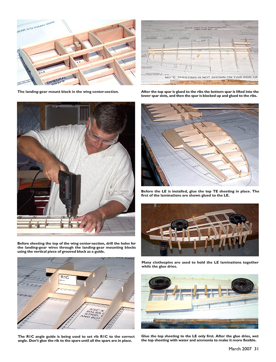
- Place landing-gear mounts on the plans and glue remaining R1 and R1A ribs to the forward spar. Glue top forward and rear spars to the ribs.
- Lift the lower rear spar into the ribs and glue ribs to it. Pull the landing-gear mounts into the ribs and glue in place; glue the 1" blocks on top of mounts against the inboard R1A rib.
- Glue 3/8" balsa leading edge (LE) to the center-section and then glue the 1/8" plywood wing-dowel support to the LE. Glue a 1" x 3/32" strip of balsa to the top of the ribs at the trailing edge (TE).
- Install 1/8" plywood dihedral supports by drilling 1/8" holes in the outermost R1 ribs between top and bottom spars, joining them to form a slot, inserting the dihedral joiner into the slot, and gluing to top and bottom spars. Ensure dihedral joiners are square to R1 ribs.
Wing — outboard panels
- Place forward and main spars on plans; pin ribs R2–R8 in place. Place rib R1C on the spar but do not pin it down.
- Lift the main spar up into all ribs and place shims under the spar at various locations to hold it into the ribs; then pin the spar to the bench.
- Keep the spar straight along the span and ensure rib building tabs contact the bench. Glue all ribs except R1C to the spar. Lift forward spar into R1C and R2 and glue to R2.
- Place the top spar on all ribs and glue it to all ribs except R1C. Glue the forward spar to R2.
- Cut the R1C angle guide from the plans, glue it to scrap plywood, cut the plywood to shape, and use it to position R1C. Place the guide on the bottom main spar between top and bottom spars against R1C; adjust R1C and glue it to top and bottom spars. Do not glue the guide to rib or spars. Move the guide to the forward spar, adjust R1C, and glue R1C to top and bottom spars.
- Glue 1/4" balsa TE to the aileron cutout. Make the cutout at least 3/32" wider than the ribs for 3/32" balsa sheeting. Glue the top 1" x 3/32" balsa sheeting to the TE at the aileron cutout. Glue 3/32" balsa sheeting to the TE inboard of the aileron.
- I used a laminated balsa LE: glue the first lamination to the ribs' LEs with CA while the wing is pinned. Use Sig-Ment or Ambroid to adhere successive laminations. Clothespins or clamps are required; clothespins may be short—work around this by placing the wing on a curved table edge with the LE overhanging, weight the wing flat, and use clothespins from top and bottom to hold laminations as glue dries.
- Glue 3/32" balsa LE sheeting to the top of the outboard wing section; spray water to help bend the sheeting if needed. When dry, sand sheeting flush with rib R1 and cut slots in R1 for dihedral braces.
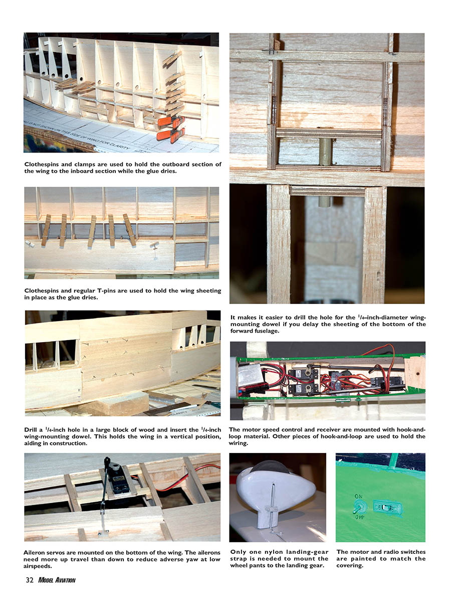
- When satisfied with outboard-to-inboard fit, glue panels together. Use many clothespins to hold R1 and R1C together from underneath.
- To strengthen the plywood dihedral joint to top and bottom spars, add 3/32" balsa fillers between spars and glue them to the plywood dihedral braces and the spars.
- Build the other outer panel the same way.
Wing finishing, mounting, and ailerons
- Round off the top of the center-section LE so the center-section fits in the fuselage wing saddle.
- Center the wing on the fuselage and drill the 1/4" wing-mount dowel hole through F2 and the wing's LE. Remove the wing, glue the 1/4" dowel in the wing.
- Sheet the bottom of the wing and glue 1/4" balsa TEs to the wing; sand to match the airfoil contour.
- Ailerons: 3/32" sheet balsa with half ribs glued top and bottom. Glue 1/4" balsa capstrips to the ribs (1/8" thick balsa for capstrips). Glue 1/4" balsa TE to the ailerons. Cut hinge slots in ailerons and wing, temporarily mount, and sand for fit.
- Install aileron-servo mount blocks per plans. Use 3/32" balsa to form a lip around the servo mount hole for the covering to adhere to.
- Adhere wingtip blocks and sand to shape. Glue 1/8" plywood wing-bolt reinforcing plate to bottom of the center-section.
Mount the wing to the fuselage, drill a 13/64" hole through wing and fuselage for the wing-mounting screw, tap the fuselage with a 1/4-20 tap, and enlarge the hole in the wing to 1/4". Glue F4A and F6 to the bottom of the wing and sheet over with 3/16" balsa. Use a sharpened brass tube to cut the access hole for the wing-mount screw.
Glue the 1/4" balsa F5s in place and sand the lower wing-fuselage fairing to match the fuselage contour. Flip the fuselage over and secure it to mount the horizontal stabilizer.
Tail surfaces, joiners, and tailwheel
- Slide horizontal stabilizer into the rear fuselage slot. Center and sight down the fuselage to confirm stabilizer and wing are parallel. Measure from wing TE to stabilizer TE on both sides to confirm symmetry. Horizontal stabilizer incidence should be approximately 1/2° LE down. When satisfied, glue in place.
- Mount vertical stabilizer with pins. Sight down the top of the fuselage from the front to avoid offset. Adjust so the vertical stabilizer is 90° to the horizontal stabilizer, then glue.
- Elevator joiner: bend from 1/8" music wire and temporarily mount elevator and rudder.
- Tailwheel bracket: use 1/16" music wire bent to shape and mounted in fuselage with 1/16" ID brass tube. Bend the bottom bracket for the axle, slip on a small washer to keep the tail wheel from pushing the rudder up, solder washer to the wire, drill a hole in the fuselage with the sharpened brass tube, glue the brass tube in place, cut to length, slip the music wire into the brass tube and bend the top of the bracket to fit into the rudder.
Landing gear and wheel pants
- Bend main landing gear from 3/16" music wire.
- Wheel pants are built from various thicknesses of balsa. The core thickness depends on wheel thickness plus wheel collars. If flying from grass, cut the bottoms so more wheel is exposed than shown on plans. Photos show full-scale Vals with and without wheel pants—building them is optional.
- Glue wheel-pant pieces together and sand to shape.
Fillet (optional)
The full-scale Val has a large wing-to-fuselage fillet; it is drawn on the plans but optional.
- Cut the fillet base from 1/64" plywood. Loosely mount wing and slip the fillet base between wing and fuselage. When satisfied, tighten wing, glue fillet to fuselage only.
- Glue soft balsa blocks to the fuselage, carve and sand them to fillet shape.
Canopy, cockpit, pilot/gunner, and finishing
- I used a canopy from the Great Planes AT-6 Texan ARF. I cut excess plastic as if mounting it for the original model, placed the canopy on top of the fuselage, pressed it down until the windscreen touched the fuselage, and marked where to trim with a dry-erase marker. Remove marks, tape canopy in place, and mark the fuselage to remove covering in the cockpit area and replace it with black MonoKote for cockpit rim.
- Cut a small strip of the black covering so the canopy glue will adhere to bare wood on the fuselage. Use a sharpened brass tube to cut cooling holes in the cockpit area.
- Pilot and gunner: I wanted simple flat figures. I scanned a picture of a pilot and gunner, enlarged to scale, created a mirror image, glued one image to 1/64" plywood, cut to shape, glued the mirror image to the other side, and darkened the plywood edge with a marker. Glue the figures into slots in the cockpit. Glue canopy in place with canopy glue (Formula 560 or similar).
- Final-sand the fuselage and cover with your covering of choice. I used MonoKote and loosely based the color scheme on a Val from the carrier Akagi at Midway. I used red "meatballs" from old decals.
Bomb release and radio placement
- I mounted an old Vortac bomb release to the bottom of the wing near the CG. If you mount a bomb release, be careful not to cut the wing spars when making the cutout—use a T-pin to poke through the wing sheeting to locate spars.
- Mount the bomb-release servo upside down in the wing so a servo arm actuates the release.
- The Val's nose is short; mount radio gear as far forward as possible. I still added lead to the nose to achieve the desired CG.
- Aileron servos are mounted to the bottom of the wing and connected to the receiver with a Y-harness.
Recommended control throws (starting point)
- Rudder: 1" left and right
- Elevator: 1/2" up and down
- Ailerons: 1/4" down and 1/2" up
Notes:
- Ailerons need more up than down travel. Mount the servo arm on the servo at roughly a 45° angle toward the front of the airplane to achieve this.
- These are good starting points; adjust throws to suit flying style.
Flying
If you've skipped ahead, here's how the Val flies: it handles much like an advanced trainer. If the only models you've flown are high-wing trainers and you want to move to a low-wing trainer, this may be the airplane you're looking for.
First flight summary:
- Performed on a cool, windless morning. After range-checking the radio with the motor on, I taxied to the runway, slowly advanced throttle, and kept the Val straight with rudder despite a left pull. After roughly 150 ft I applied up-elevator and the Val became airborne in a realistic manner.
- Trim required: some up-elevator and a little right aileron. Once trimmed, low passes were easy and the model was well behaved.
- Slow flight: the Val was able to fly quite slowly before stalling. The right wing tended to drop at the stall, but the model remained easy to control up to the stall.
- Approaches and landings: the big prop windmills and creates drag; keep a little power on in the approach or make steeper approaches to maintain airspeed. The Val does not float excessively when power is cut; it doesn't drop like a brick either.
- Repairs: I found a slight warp in the right wing after flying; reheating the MonoKote and twisting removed the warp. I later redrew the plans to show 1/2° incidence in the horizontal stabilizer.
- Aerobatics: the Val will fly inverted with a little down-elevator, rolls are crisp, and there is little roll/rudder coupling. Landings are easy—you can wheel on, three-point, or one-point on the tailwheel if careful.
If you want a model that will amaze in aerobatic competitions, the Val may not be extreme enough. But if you want an advanced trainer that looks like a full-scale airplane or a simple Fun Scale contest entry, this is a great fit.
MA
Gary Fuller
Transcribed from original scans by AI. Minor OCR errors may remain.

