
Skis for Snow Operations
Ray Gareau
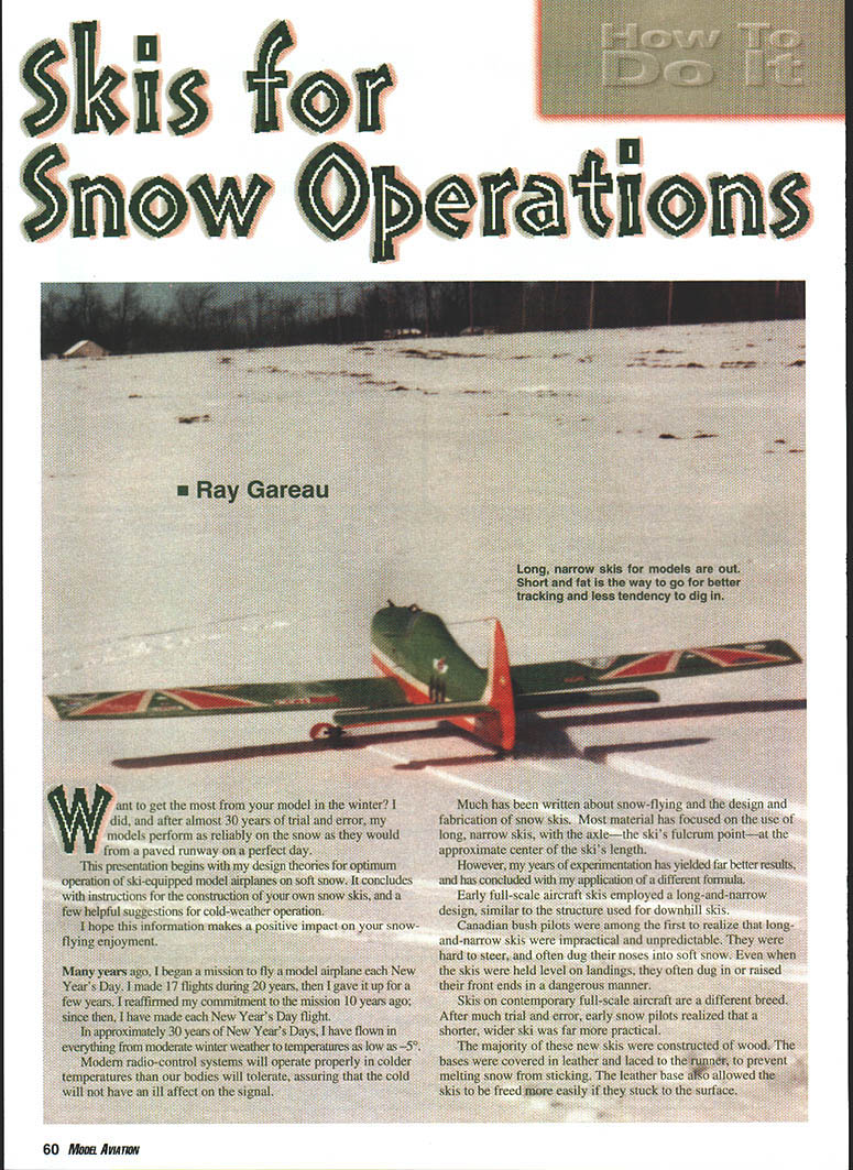
Want to get the most from your model in the winter? I did, and after almost 30 years of trial and error, my models perform as reliably on the snow as they would from a paved runway on a perfect day.
This presentation begins with my design theories for optimum operation of ski-equipped model airplanes on soft snow. It concludes with instructions for the construction of your own snow skis, and a few helpful suggestions for cold-weather operation.
I hope this information makes a positive impact on your snow-flying enjoyment.
Many years ago, I began a mission to fly a model airplane each New Year’s Day. I made 17 flights during 20 years, then I gave it up for a few years. I reaffirmed my commitment to the mission 10 years ago; since then, I have made each New Year’s Day flight.
In approximately 30 years of New Year’s Days, I have flown in everything from moderate winter weather to temperatures as low as -5°.
Modern radio-control systems will operate properly in colder temperatures than our bodies will tolerate, assuring that the cold will not have an ill effect on the signal.
Much has been written about snow-flying and the design and fabrication of snow skis. Most material has focused on the use of long, narrow skis, with the axle—the ski’s fulcrum point—at the approximate center of the ski’s length.
However, my years of experimentation have yielded far better results, and have concluded with my application of a different formula.
Early full-scale aircraft skis employed a long-and-narrow design, similar to the structure used for downhill skis.
Canadian bush pilots were among the first to realize that long-and-narrow skis were impractical and unpredictable. They were hard to steer, and often dug their noses into soft snow. Even when the skis were held level on landings, they often dug in or raised their front ends in a dangerous manner.
Skis on contemporary full-scale aircraft are a different breed. After much trial and error, early snow pilots realized that a shorter, wider ski was far more practical.
The majority of these new skis were constructed of wood. The bases were covered in leather and laced to the runner, to prevent melting snow from sticking. The leather base also allowed the skis to be freed more easily if they stuck to the surface.
Shorter skis were more predictable than the longer ones, and their overall performance was superior, but the design still called for the axle to be at the ski's midway point.
During the mid-1950s, designers began to experiment with moving the axle rearward. Their work resulted in the contemporary ski design—short and wide, with a rearward mounting point.
Skis used today on typical high-wing Piper, Aeronca, Cessna, and similar full-scale aircraft are shorter and wider than ever, with their axles located very near the heel of the runner. These skis are very effective on all snow textures, they steer with ease, they rise quickly on any surface, and they produce far less drag in flight.
More often than not, full-scale ski-equipped airplanes operate from packed surfaces. When power is applied and the resistance of the surface manifests itself, the resultant down-force makes the ski dig in harder.
If power is further increased in a typical single-engine airplane, the ski can eventually let go and bounce into the propeller. This results in propeller and ski damage—and possibly worse.
Few full-scale airplanes equipped with tricycle gear are enlisted for use with skis. However, one exception to the no-trike-gear rule is the de Havilland Twin Otter. The Otter is a twin-engine aircraft, so there is less risk of propeller damage in the event the ski digs in. The Otter has been flown on skis for years, and is popular for operations in the High Arctic.
The same principles can be applied to ski design for models as for full-scale practice.
I have flown from snow-covered surfaces for more than 30 years. I've made all the mistakes, but I've evaluated each performance carefully, applying whatever modifications were necessary to improve my models' takeoffs and landings.
As did other ski designers, I started with the axle at 50%. As I moved the axles toward the rear, I was amazed by the skis' ability to rise immediately as the airplane moved forward over the snow.
Once the ideal rearward fulcrum point was attained, each takeoff and landing became picture perfect. Nose-overs were memories, replaced by picturesque lengths of beautifully carved tracks in the snow.
Full-scale Norseman skis had axles located at approximately 1/3 of the ski length from the rear. I was on the right track.
My next experiment was to move the axle even farther back, to approximately 25% from the rear. That is closer to what I had observed on full-scale J-3s and Taylorcrafts. That was the ticket!
My final formula works very well when applied to .40-size models that weigh approximately six pounds, and are flown from snow more than six inches deep. This formula determines the ski size according to the airplane's weight.
Give the skis one inch of width, collectively, for each pound the model weighs. Subtract one inch from the total width. A ski's length should be approximately three times its width, so my formula reads as follows.
- Weight in pounds equals total ski width in inches minus one inch.
- Divide the total width by two to determine the width of each ski.
- Multiply width times three to determine the ideal length.
Example:
- A six-pound model will have a total ski width of five inches. There are two skis, so divide the five-inch figure by two, which results in 2½-inch-wide skis. Multiply the width by three to determine the ideal length of 7½ inches.
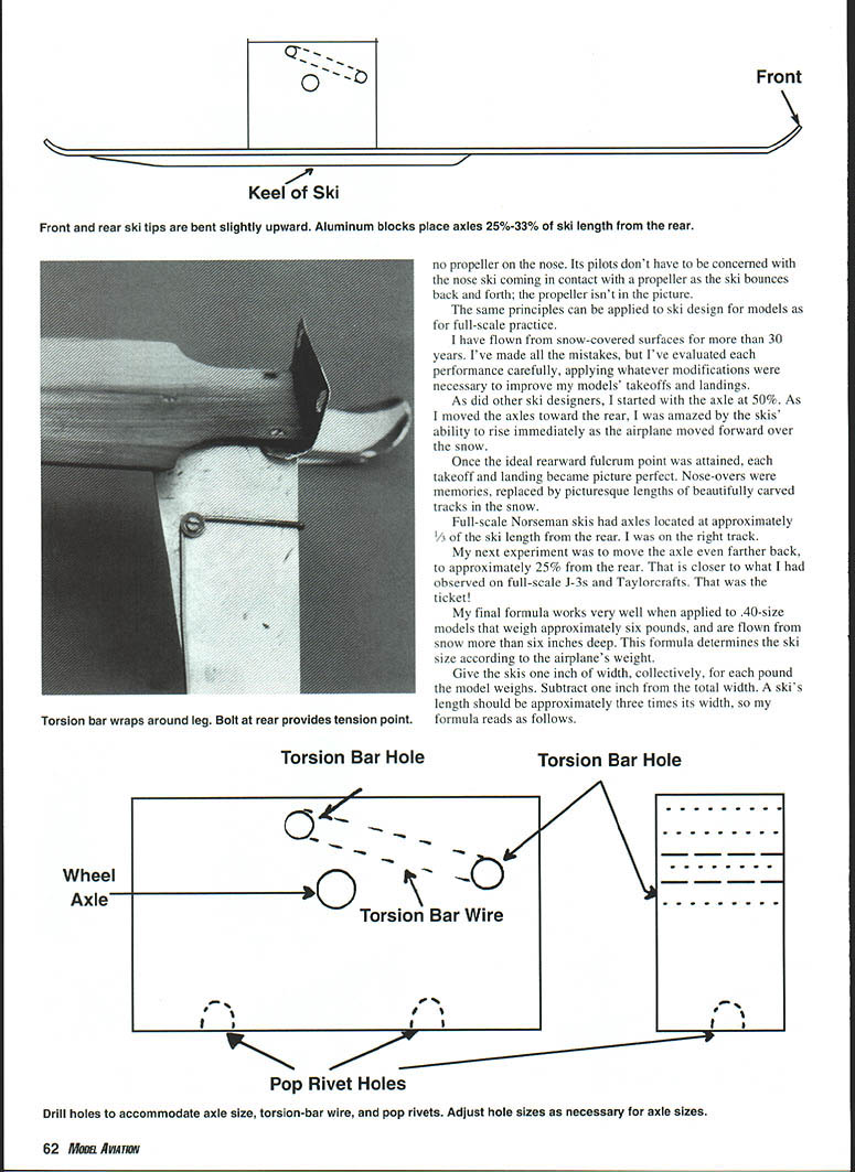
Position the axle anywhere from 25% to 33% from the rear of the ski. I use a bolt to fasten a small tail ski to a tail bumper. The front end attaches to one of the retaining screws with a short piece of nylon leader line, or its equivalent. Tie the leader line so that the ski takes a positive angle.
The length of the tail ski can be the same as the width of a main ski—2½ inches in this case. Use the W × 3 = L formula to reach an approximate length of 3/4–7/8 inch for the tail ski.
Model application
Because model aircraft are relatively light and their speed much lower, skis can be made with surprisingly small dimensions. The most critical factor in ski performance is the relation of the axle to the ski's length. Experience has shown that the axle should be located at approximately 0.40 of the ski length, measured from the tail. This rearward position gives improved steering, less tendency to dig the nose, and better flotation.
Construction materials
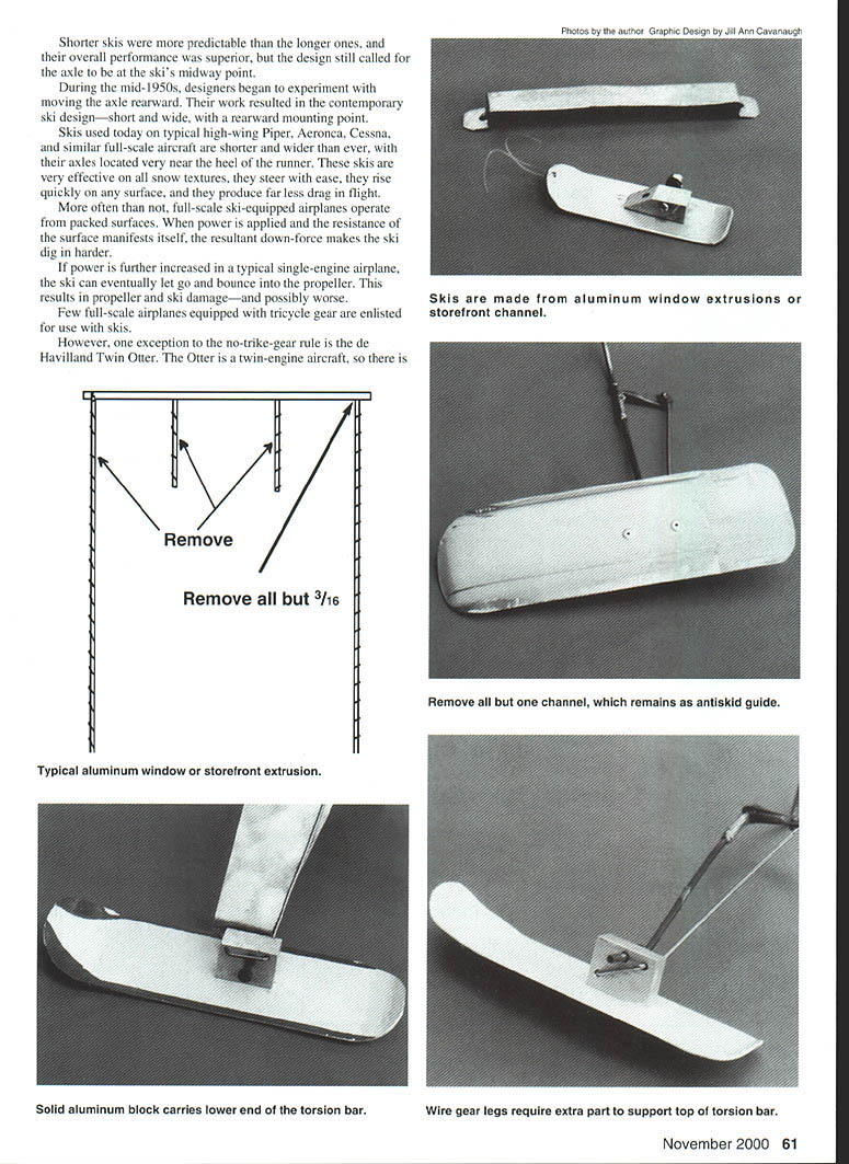
Commercially available aluminum window and storefront extrusions make excellent stock for model skis. Typical extrusions are 1-1/2 to 2 in. wide; cut two pieces to the desired ski length and rivet or weld them together. Remove all but one channel, which remains as an antiskid guide, and round the ends. A solid aluminum block carries the lower end of the torsion bar.
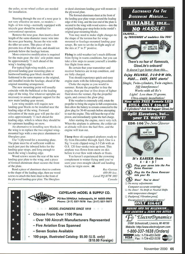
For tail-dragger models, a simple strap and block arrangement is adequate to secure the ski to the landing gear. For models with wire gear, wire gear legs require an extra part to support the top of the torsion bar.
ABS (Acrylonitrile Butadiene Styrene) plastic is a reasonable alternative to aluminum, although it is more difficult to form than aluminum. ABS blisters easily, and heat must be used to bend ABS at the tips of the skis.
If the material is anodized, it will do a better job of melting the snow.
Construction steps
- Cut the extrusion for each ski, using the W × 3 = L formula to determine length.
- Remove all but one of the channels that run down the length of each extrusion. This remaining channel will serve as an antiskid guide, and should be trimmed to extend approximately 3/16 inch from the extrusion.
- I use a band saw with a fine-tooth blade to remove the channels; this facilitates the process and reduces the amount of filing required to clean things up.
- It's easier to retain an outer channel than a center channel.
- Clamp the extrusion in a vise, then form the nose of the ski by gradually bending the front of the extrusion upward approximately 1/2 inch.
- Bend the rear end of the ski slightly upward, to prevent the ski from digging in if the airplane is pushed backward during preparation or maintenance.
- Make two axle-mounting blocks. Each is made from a 1/2 × 1 1/4 × 1 1/2-inch block of solid aluminum.
- Drill a 7/32-inch hole in each block to accommodate the axle, and drill two 5/64-inch holes for the torsion bar. Change hole sizes as necessary to accommodate axles that are larger or smaller in diameter.
- Aluminum sheeting may be used in place of solid blocks. Bend 1/16-inch sheet to a "U" shape, then drill the axle and torsion bar holes at the same locations.
- Use cyanoacrylate (CyA) to tack-glue the blocks in their correct positions on the tops of the skis, then drill appropriate-size holes through the skis and into the blocks.
- Use two pop rivets to fasten each block to the top of each ski.
- If a solid, dural-type landing gear is used, drill a hole in the upper portion of each gear leg to accept the 4-40 bolt that keeps the torsion bar against the rear of the leg.
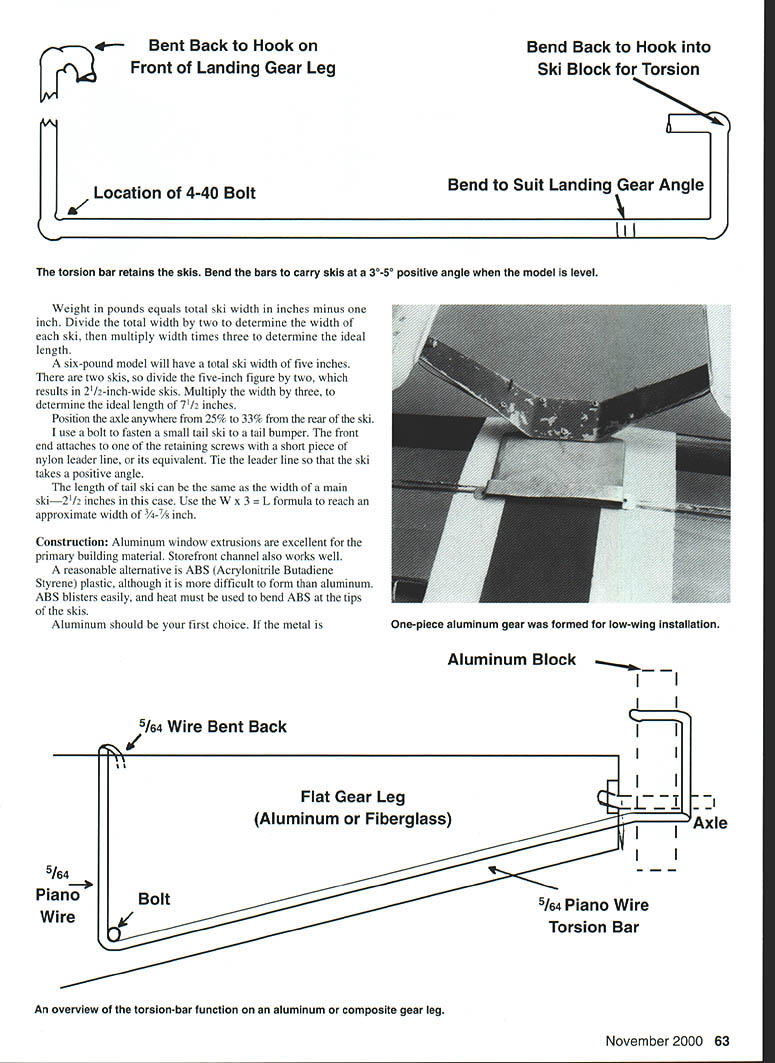
- Torsion bars are bent from music wire.
- Use 5/64 wire for airplanes weighing as much as eight pounds. Alternative wire diameters are 3/32 or .078. Use your own judgment when weight is four pounds or greater.
- Rubber bands have been used to perform the torsion-bar function in many older ski designs, but there is a problem with rubber: stretched rubber doesn't always return when it's cold, so its performance was poor. Music wire is ideal.
- Bend the torsion bars to produce a 3°–5° positive ski angle when the model is level with the ground. The angle of the skis must never be negative.
- With the torsion bar already bent to shape and fitted to the axle block, slip the ski over the axle.
- Bring the forward bend of the torsion bar over the front of the gear leg, then trap the torsion bar's dogleg with the 4-40 retaining bolt and a flat washer.
- The bend of the torsion bars prevents the skis from slipping off the leg.
Gear modifications and mounting
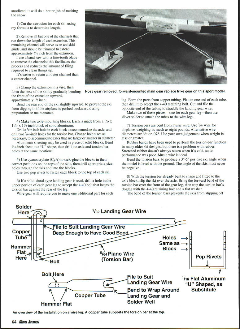
Steering through the use of a nose gear is not very effective on snow, so models—high- or low-wing—normally equipped with tricycle gear should be modified for conventional operation.
- Remove the nose gear, then insert a short length of starter music wire into the nose gear bearing. Secure the wire with the little set screw. This piece of wire prevents loss of the tiller arm, and should not protrude below the fuselage bottom.
More-extensive modification is required for the main gear; the skis' axle points must be approximately 1/2 inch ahead of the wing's leading edge.
- For typical high-wing models, a new plywood landing-gear mounting plate or hardwood landing-gear block should be fashioned in the same manner as the original, and installed inside the fuselage, ahead of the original mounting arrangement. The new mounting point will usually coincide with the bulkhead at the leading edge of the wing. Use whatever uprights are necessary to assure adequate support for the new main landing-gear mount.
- Low-wing models will require new landing-gear blocks to be installed near the leading edge of the wing. Forward relocation of the main gear will put the skis' axles approximately 1/2 inch ahead of the leading edge, which is where they should be for optimum handling on snow.
An alternative to installing new blocks in the wing is to replace the two original wing-mounted legs with a one-piece aluminum or fiberglass gear.
- Use 1/4-inch plywood for a mounting plate. The plate must be of sufficient width to reach just past the inboard holes for the landing-gear straps, and long enough to reach the wing's leading edge.
- Wood screws secure the rear of the new landing-gear plate to the wing, and a piece of formed aluminum sheet secures the front of the plate.
- Bend a piece of aluminum sheet to conform to the shape of the leading edge, then use wood screws to attach this bent sheet to the front of the plywood landing-gear plate. The fiberglass or dural aluminum landing gear will mount on the plywood plate.
- The formed-aluminum sheet at the front of the landing-gear plate wraps around the leading edge of the wing, and the rear end of the plate is secured to the wing with wood screws into the original landing-gear-strap holes in the model's original gear-mounting blocks.
You may need to make slight changes to the shape of the torsion bar for wing-mounted or fuselage-mounted landing gear setups. Be sure to set the in-flight angle of the skis at 3° to 5° positive.
Cold-weather operation
Flying in cold weather isn't much different from flying in warm conditions, but you can take a few steps to assure yourself a trouble-free flight from snow.
- Be certain that your transmitter and receiver batteries are in top condition, and are fully charged.
You should experience quick-and-easy engine starts with the following procedure:
- Choke the engine as you would in summer.
- Rotate the propeller to free the engine, then put four or five drops of lighter fluid down the venturi, flip the propeller again, and connect the glow plug.
- If the weather is extremely cold, rotate the propeller to bring the engine to full compression, then allow the battery to remain connected to the glow plug for 30–40 seconds before attempting to start the engine. This will heat the top of the piston, and immediately ignite the fuel charge.
- After starting the engine, run it very rich. When the airplane is airborne, the colder air at altitude will slow the fuel flow, and the engine will lean out.
I keep three ski-equipped airplanes ready to fly from December through April. One is a Sig 1/4-scale clipped-wing J-3 Cub with an O.S. 120 four-stroke twin up front. This airplane was flown from snow on skis before it ever flew with wheels or floats.
You haven’t experienced the crowning complement to winter flying until you’ve seen your own straight takeoff and landing tracks in virgin snow.
Ray Garneau 489-89e Ave. Laval PQ H7W 3H3 Canada
Transcribed from original scans by AI. Minor OCR errors may remain.

