
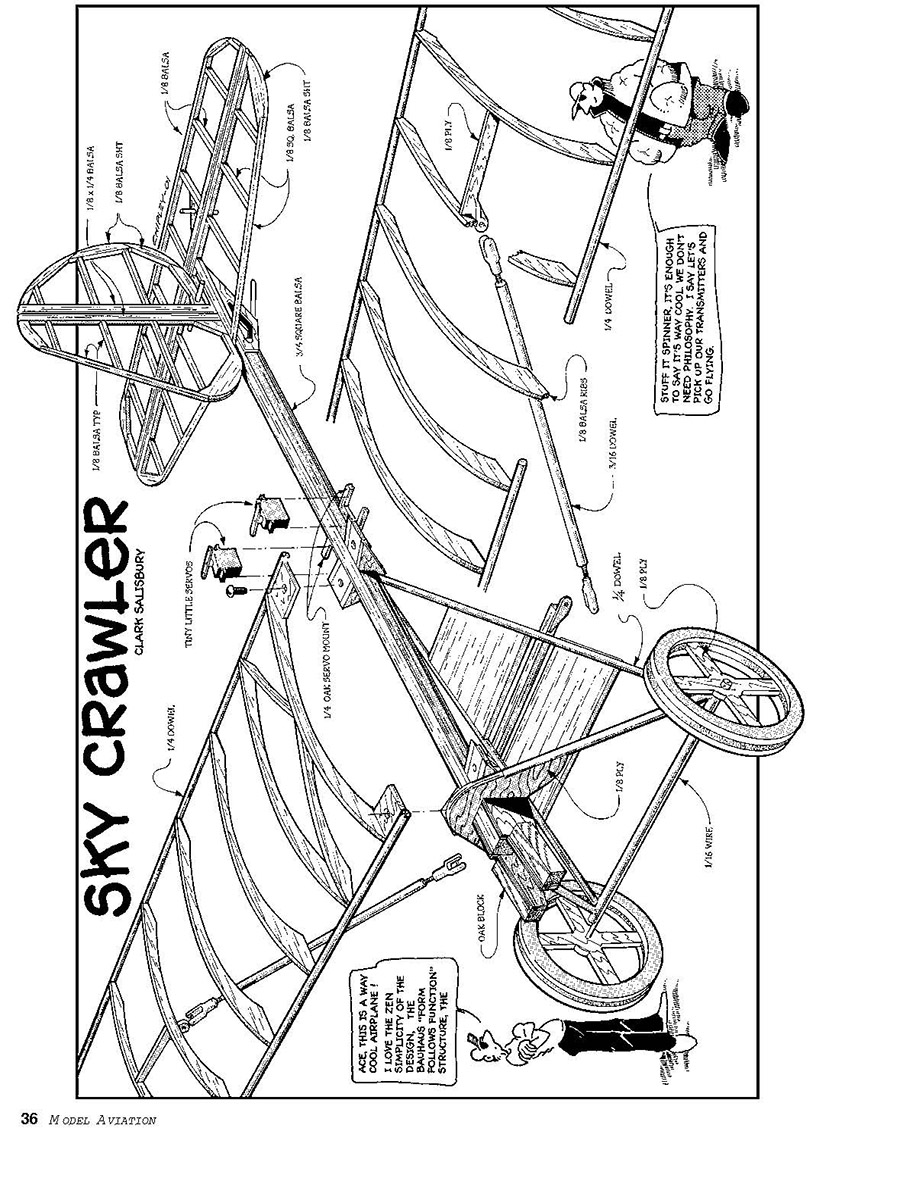
Sky Crawler
Before we build SkyCrawler, I would like to share a few thoughts on coming up with this type of airplane in the first place.
I live in Cache Valley, which is located at about 4,500 feet elevation in northern Utah. We are blessed, for the time being, to be able to fly on an abandoned runway at our local airport. That situation may change in the future, and our club has been very worried about that possibility.
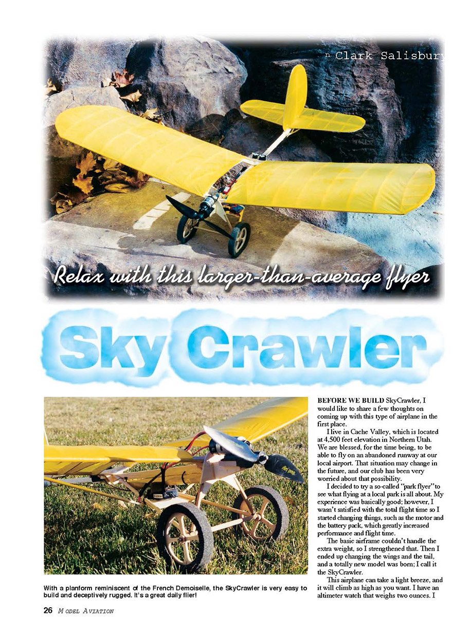
I decided to try a so-called "park flyer" to see what flying at a local park is all about. My experience was basically good; however, I wasn't satisfied with the total flight time, so I started changing things, such as the motor and the battery pack, which greatly increased performance and flight time. The basic airframe couldn't handle the extra weight, so I strengthened that. Then I ended up changing the wings and the tail, and a totally new model was born; I call it the SkyCrawler.
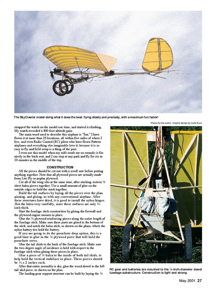
This airplane can take a light breeze, and it will climb as high as you want. I have an altimeter watch that weighs two ounces. I strapped the watch on the model one time and started it climbing. My watch recorded a 400-foot altitude gain. The main word used to describe this airplane is "fun." I have flown it at more than 25 locations, all within five miles of where I live, and even RC pilots who have flown Pattern airplanes and everything else imaginable love it, because it is so easy to fly and field setup is a thing of the past. I even use this model when my wife sends me on errands; it fits nicely in the back seat, and I can stop at any park and fly for six to ten minutes in the middle of the trip.
Construction
- Cut all pieces with a scroll saw before assembly. All plywood pieces are made from Lite Ply or poplar plywood.
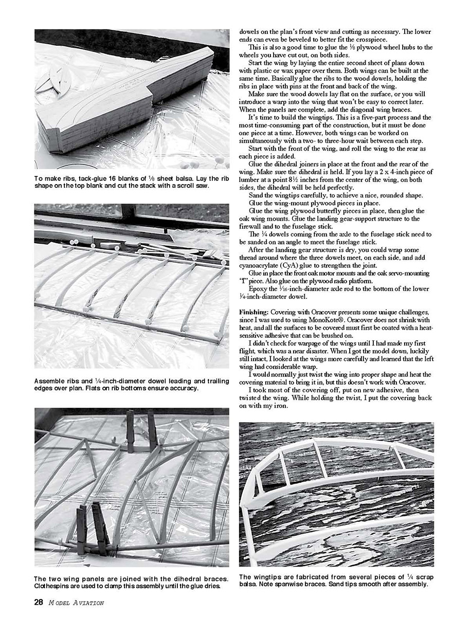
- Make ribs by tacking/gluing 16 blanks of 1/8-inch sheet balsa together. Lay the rib shape on the top blank and cut the stack with a scroll saw. Use a small amount of glue on the outside edges to hold the stack while cutting.
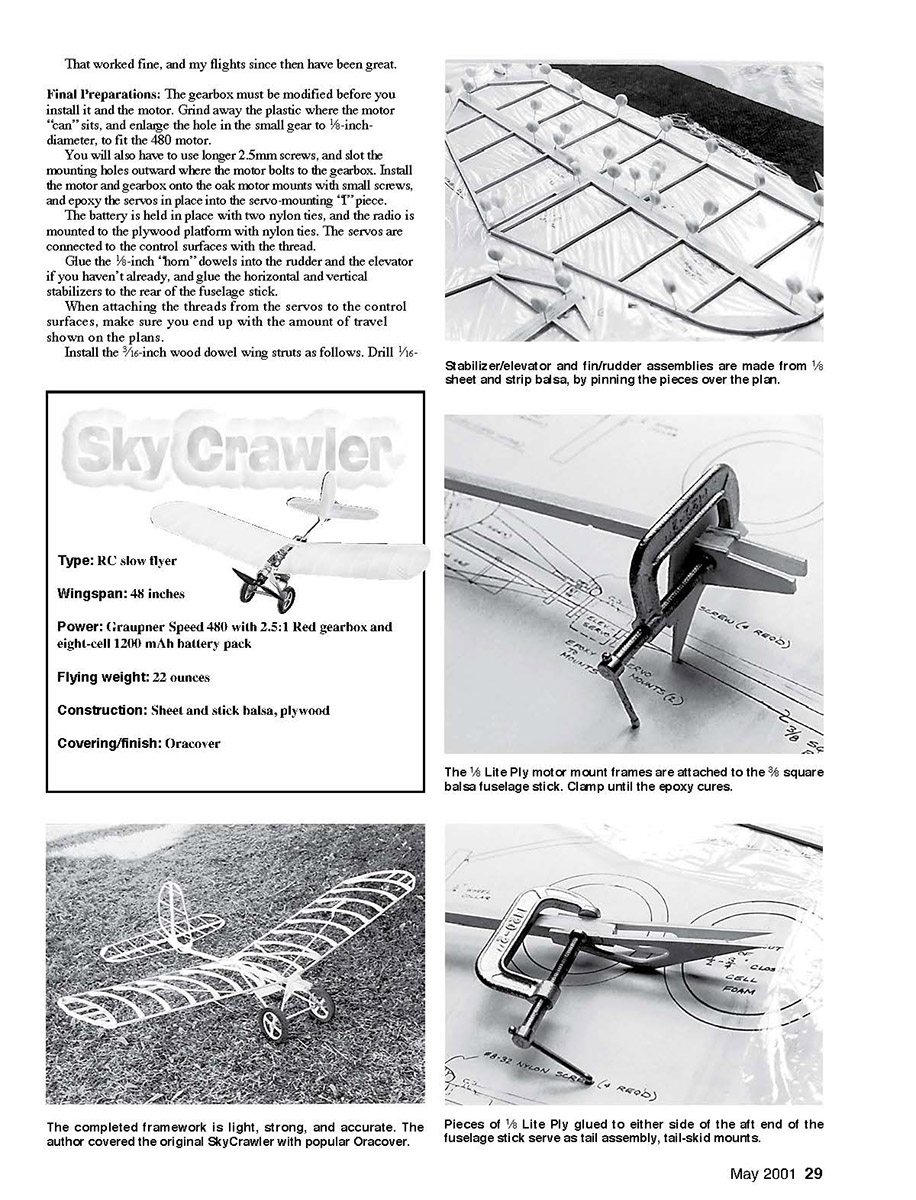
- Build tail surfaces by laying parts over the plan, pinning, and gluing as with any conventional airplane. After drying, install nylon hinges. Slot the balsa very carefully — these surfaces are only 1/8 inch thick.
- Begin the fuselage stick construction by gluing the firewall and plywood engine mounts in place. Glue 1/8-inch plywood reinforcing pieces along the entire bottom length of the fuselage stick. Notch the balsa stick where the nylon battery ties will hold the battery, as shown on the plans.
- If you plan to use the parachute-drop option, glue in the 1/8-inch plywood piece that will hold the parachute servo at this stage.
- Glue the tail skids to the back of the fuselage stick, maintaining a two-degree angle of incidence relative to the fuselage stick. Glue a piece of 1/8-inch balsa (1/4 x 2 inches) to the inside of both tail skids to help hold the vertical stabilizer. After the assembly is dry, glue the wood dowel to the left tail skid piece as shown on the plan.
- Build the landing-gear support by laying 1/4-inch-diameter dowel leading and trailing edges and ribs over the plan. Flats on rib bottoms ensure accuracy. Bevel the lower ends as necessary to fit the crosspiece.
- Glue 1/8-inch plywood wheel hubs to the wheels you have cut out on both sides.
- Start the wing by laying a second sheet of plans down with plastic or wax paper over them. Both wings can be built at the same time. Glue ribs to the wood dowels and hold them in place with pins at the front and back of the wing. Ensure dowels lay flat on the building surface to avoid warps. When panels are complete, add diagonal wing braces.
- Wingtips are a five-part process and the most time-consuming part of construction. Build them one piece at a time, working both wings simultaneously with a two- to three-hour wait between steps. Start with the front of the wing and roll the wing to the rear as each piece is added.
- Glue the dihedral joiners in place at the front and rear of the wing. Hold the dihedral while the glue dries; laying a 2 x 4-inch piece of lumber at a point 8-1/2 inches from the center of the wing on both sides will keep the dihedral accurate.
- Sand the wingtips carefully to achieve a nice, rounded shape.
- Glue the wing-mount plywood pieces and the plywood butterfly pieces in place, then glue the oak wing mounts.
- Glue the landing-gear-support structure to the firewall and to the fuselage stick. Sand the 1/4-inch dowels coming from the axle on an angle to meet the fuselage stick. After the landing-gear structure is dry, you may wrap some thread around the joint where the three dowels meet on each side and add cyanoacrylate (CyA) glue to strengthen the joint.
- Epoxy the 1/16-inch-diameter axle rod to the bottom of the lower 1/4-inch-diameter dowel.
- Glue the front oak motor mounts and the oak servo-mounting "T" piece in place. Also glue on the plywood radio platform. Epoxy the servos into the servo-mounting "T" piece.
- Install the 3/16-inch wood dowel wing struts per the plans. Drill 3/32-inch-diameter holes into both ends of the dowels. Insert 1/4-inch threaded rods into both ends of the dowels and put a drop of epoxy on the threaded rods as you screw them into the dowels.
- Adjust the nylon clevises to meet the wing and slide a small piece of silicone fuel line over the clevises so they don't come off in flight.
- The wing is held in place with four 8-32 nylon screws, as shown on the plan. Drill and tap the plywood mounts on the fuselage to 8-32 and drill holes in the plywood pieces aft of the center of the wing so the nylon screws can be installed.
- The battery is held in place with two nylon ties. Mount the radio to the plywood platform with nylon ties. Connect the servos to the control surfaces with thread. Glue 1/8-inch "horn" dowels into the rudder and elevator if you haven't already, and glue the horizontal and vertical stabilizers to the rear of the fuselage stick.
- When attaching servo threads to the control surfaces, make sure you end up with the amount of travel shown on the plans.
Finishing
- Covering with Oracover differs from MonoKote. Oracover does not shrink with heat; all surfaces to be covered must first be coated with a heat-sensitive adhesive that can be brushed on.
- I didn't check for wing warp until after my first flight, which was a near disaster. The left wing had considerable warp. With Oracover, you cannot simply twist the wing and heat the covering to correct warp.
- Remedy: remove most of the covering, brush on new adhesive, twist the wing into proper shape, and while holding the twist put the covering back on with your iron. That worked fine and subsequent flights have been great.
Final Preparations
- Modify the gearbox before installing it and the motor: grind away the plastic where the motor "can" sits and enlarge the hole in the small gear to 5/16-inch diameter to fit the Speed 480 motor.
- Use longer 2.5mm screws and slot the mounting holes outward where the motor bolts to the gearbox. Install the motor and gearbox onto the oak motor mounts with small screws.
- Install and epoxy the servos in place in the servo-mounting "T" piece. Secure the battery and radio as noted above. Check control throws against the plans and trim as needed.
Flying
- SkyCrawler is a slow flyer (about 5 to 10 mph) and handles best in a light breeze (no more than 3 to 4 mph). It is not an acrobatic airplane but is extremely fun to fly.
- Because of the slow speed, it can be hand-launched with just a walk. Use a slight hand-level launch: hold the radio in your left hand and launch with your right. It takes two to three seconds to transfer the radio from your left hand to your right after launch, so be sure trims and adjustments are correct so the airplane will fly level.
- I once launched with incorrect trim and had to build a new airplane — be careful.
- You should be able to fly SkyCrawler in any park as large as a regulation baseball diamond, even with light pockets around the field. Expect people to stop and watch.
Parachute-drop Option
- For fun, SkyCrawler can carry a small parachute and release it in flight. I installed a third servo that pulls a pin to release a rubber band holding the parachute.
- I made the parachute from a 26-inch-diameter circle cut from a plastic grocery bag and attached a 3-ounce weight using six strings. The parachute is stowed under the battery and held by a rubber band.
- The parachute-drop servo is installed with a "T" harness and mounted common with the elevator servo so aileron and rudder channels remain available.
- Pushing the elevator stick full forward (down elevator) also pulls the pin to release the parachute. The release takes only a half-second and the airplane hardly noses down. Kids especially enjoy retrieving the parachute.
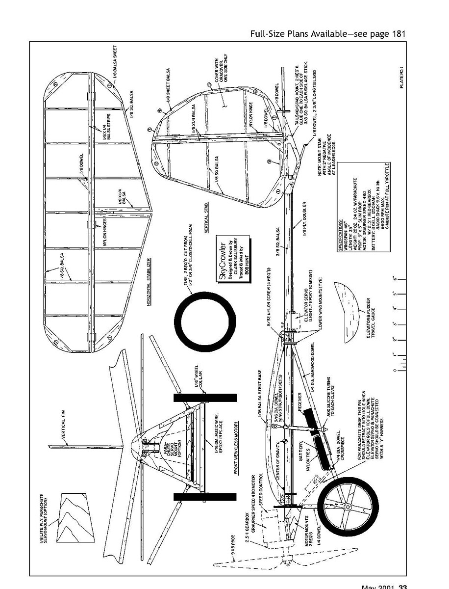
Specifications
- Type: RC slow flyer
- Wingspan: 48 inches
- Power: Graupner Speed 480 with 2.5:1 Red gearbox and eight-cell 1200 mAh battery pack
- Flying weight: 22 ounces
- Construction: Sheet-and-stick balsa, plywood
- Covering/finish: Oracover
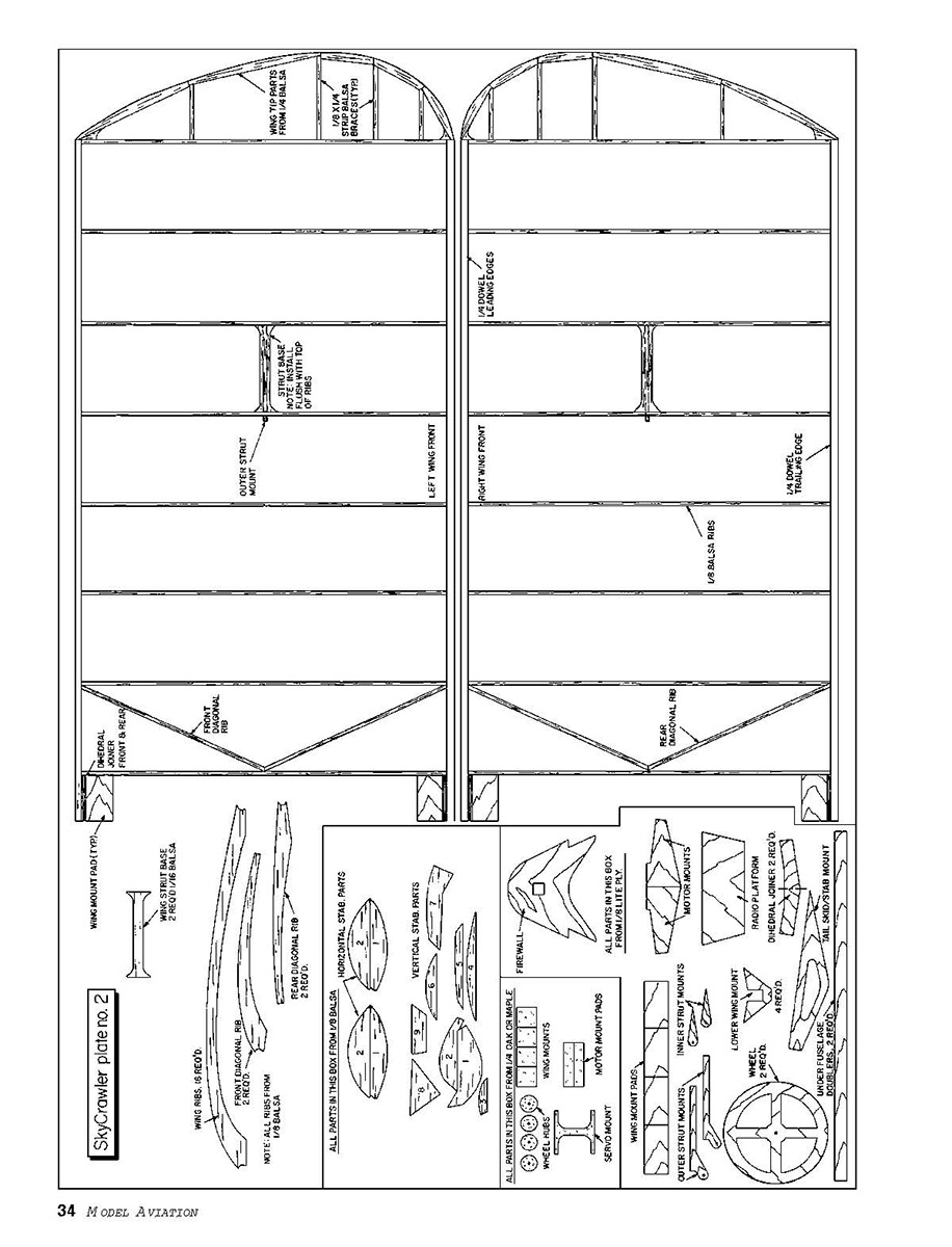
Plans
- SkyCrawler plate no. 2: full-page SkyCrawler plan (drawings and part labels). No additional running article text on that page.
Clark Salisbury 571 E. 1260 N. North Logan, UT 84341
Transcribed from original scans by AI. Minor OCR errors may remain.

