
Sky Shark
John Hunton with Seena Vasan
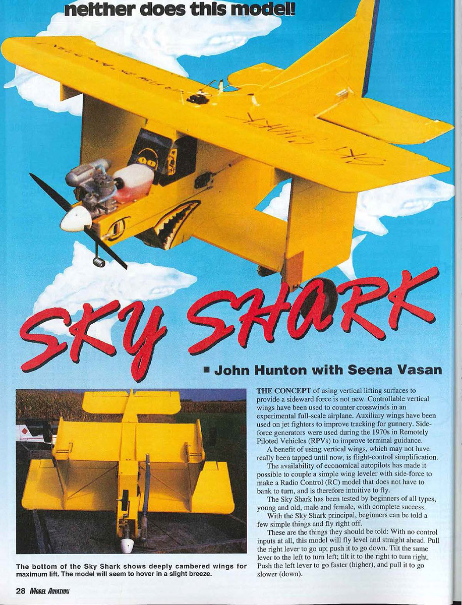
THE CONCEPT of using vertical lifting surfaces to provide a sideward force is not new. Controllable vertical wings have been used to counter crosswinds in an experimental full-scale airplane. Auxiliary wings have been used on jet fighters to improve tracking for gunnery. Side-force generators were used during the 1970s in Remotely Piloted Vehicles (RPVs) to improve terminal guidance.
A benefit of using vertical wings, which may not have really been tapped until now, is flight-control simplification.
The availability of economical autopilots has made it possible to couple a simple wing leveler with side-force to make a Radio Control (RC) model that does not have to bank to turn, and is therefore intuitive to fly.
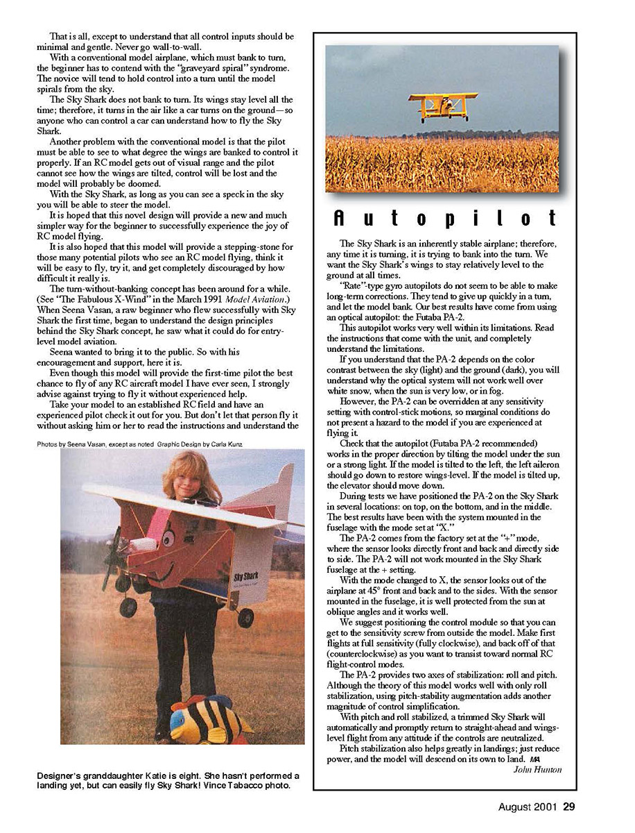
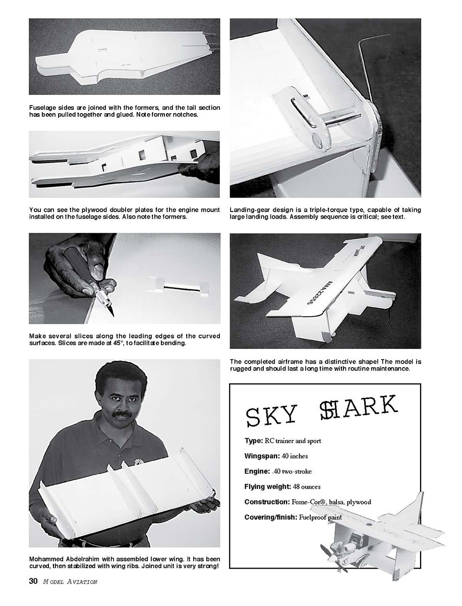
The Sky Shark has been tested by beginners of all types, young and old, male and female, with complete success.
With the Sky Shark principle, beginners can be told a few simple things and fly right off.
These are the things they should be told:
- With no control inputs at all, this model will fly level and straight ahead.
- Pull the right lever to go up; push it to go down.
- Tilt the same lever to the left to turn left; tilt it to the right to turn right.
- Push the left lever to go faster (higher), and pull it to go slower (down).
That is all, except to understand that all control inputs should be minimal and gentle. Never go wall-to-wall.
With a conventional model airplane, which must bank to turn, the beginner has to contend with the "graveyard spiral" syndrome. The novice will tend to hold control into a turn until the model spirals from the sky.
The Sky Shark does not bank to turn. Its wings stay level all the time; therefore, it turns in the air like a car turns on the ground—so anyone who can control a car can understand how to fly the Sky Shark.
Another problem with the conventional model is that the pilot must be able to see to what degree the wings are banked to control it properly. If an RC model gets out of visual range and the pilot cannot see how the wings are tilted, control will be lost and the model will probably be doomed.
With the Sky Shark, as long as you can see a speck in the sky you will be able to steer the model.
It is hoped that this novel design will provide a new and much simpler way for the beginner to successfully experience the joy of RC model flying.
It is also hoped that this model will provide a stepping-stone for those many potential pilots who see an RC model flying, think it will be easy to fly, try it, and get completely discouraged by how difficult it really is.
The turn-without-banking concept has been around for a while (see "The Fabulous X-Wind" in the March 1991 Model Aviation). When Seena Vasan, a new beginner who flew successfully with Sky Shark the first time, began to understand the design principles behind the Sky Shark concept, she saw what it could do for entry-level model aviation.
Seena wanted to bring it to the public. So with his encouragement and support, here it is.
Even though this model will provide the first-time pilot the best chance to fly of any RC aircraft model I have ever seen, I strongly advise against trying to fly it without experienced help.
Take your model to an established RC field and have an experienced pilot check it out for you. But don't let that person fly it without asking him or her to read the instructions and understand the aircraft.
Autopilot
The Sky Shark is an inherently stable airplane; therefore, any time it is turning, it is trying to bank into the turn. We want the Sky Shark's wings to stay relatively level to the ground at all times.
"Rate"-type gyro autopilots do not seem to be able to make long-term corrections. They tend to give up quickly in a turn and let the model bank. Our best results have come from using an optical autopilot: the Futaba PA-2.
This autopilot works very well within its limitations. Read the instructions that come with the unit, and completely understand the limitations.
If you understand that the PA-2 depends on the color contrast between the sky (light) and the ground (dark), you will understand why the optical system will not work well over white snow, when the sun is very low, or in fog.
However, the PA-2 can be overridden in any sensitivity setting with control-stick motions, so marginal conditions do not present a hazard to the model if you are experienced at flying it.
Check that the autopilot (Futaba PA-2 recommended) works in the proper direction by tilting the model under the sun or a strong light. If the model is tilted to the left, the left aileron should go down to restore wings level. If the model is tilted up, the elevator should move down.
During tests we have positioned the PA-2 on the Sky Shark in several locations: on top, on the bottom, and in the middle. The best results have been with the system mounted in the fuselage with the mode set at "X."
The PA-2 comes from the factory set at the "+" mode, where the sensor looks directly front and back and directly side to side. The PA-2 will not work mounted in the Sky Shark fuselage at the + setting.
With the mode changed to X, the sensor looks out of the airplane at 45° front and back and to the sides. With the sensor mounted in the fuselage, it is well protected from the sun at oblique angles and it works well.
We suggest positioning the control module so that you can get to the sensitivity screw from outside the model. Make first flights at full sensitivity (fully clockwise), and back off of that (counterclockwise) as you want to transit toward normal RC flight-control modes.
The PA-2 provides two axes of stabilization: roll and pitch. Although the theory of this model works well with only roll stabilization, using pitch-stability augmentation adds another magnitude of control simplification.
With pitch and roll stabilized, a trimmed Sky Shark will automatically and promptly return to straight-ahead and wings-level flight from any attitude if the controls are neutralized.
Pitch stabilization also helps greatly in landings; just reduce power, and the model will descend on its own to land.
John Hunton
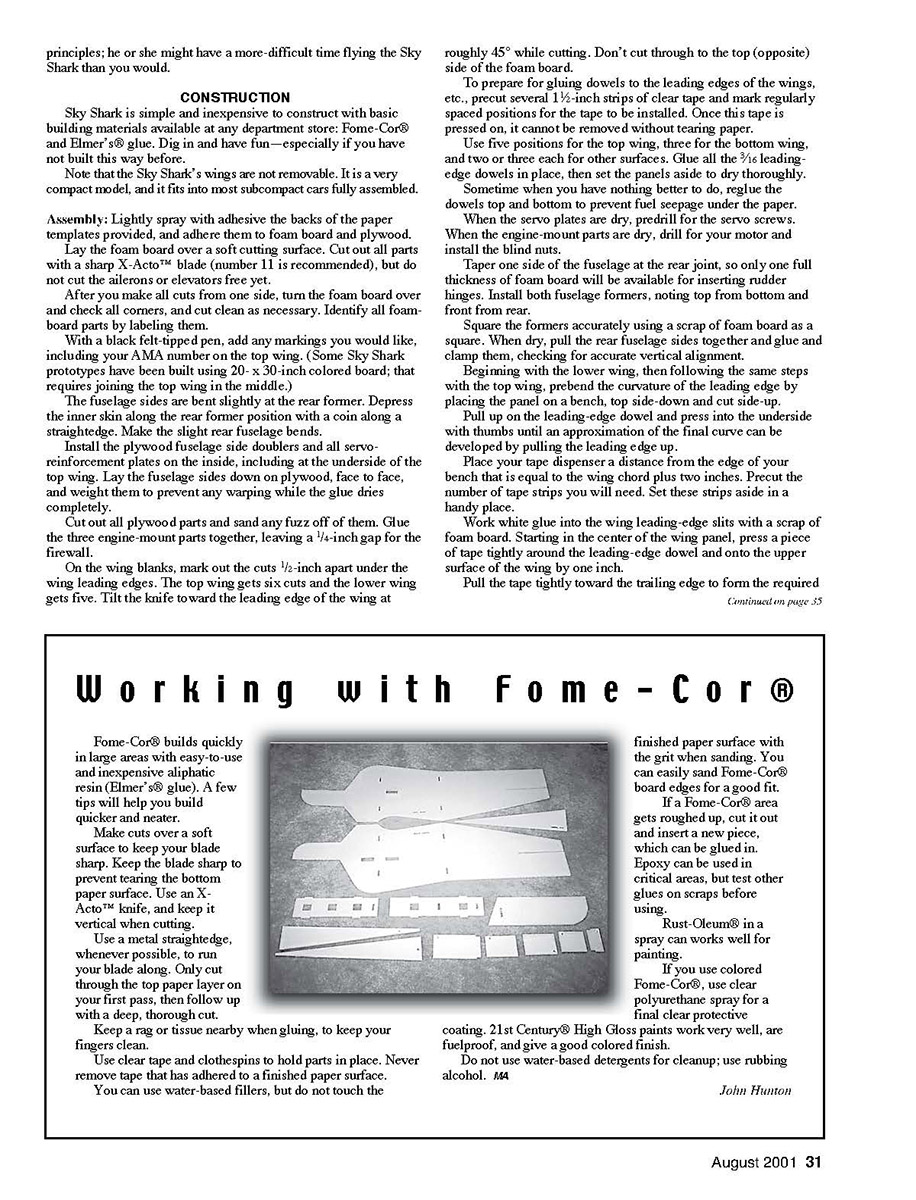
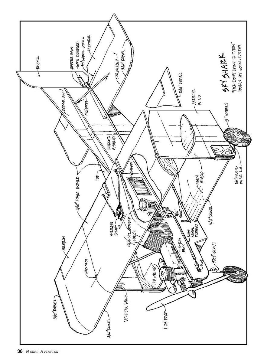
The completed airframe has a distinctive shape! The model is rugged and should last a long time with routine maintenance.
SKY SHARK (specifications)
- Type: RC trainer and sport
- Wingspan: 40 inches
- Engine: .40 two-stroke
- Flying weight: 48 ounces
- Construction: Fome-Cor®, balsa, plywood
- Covering/finish: Fuelproof paint
Construction notes
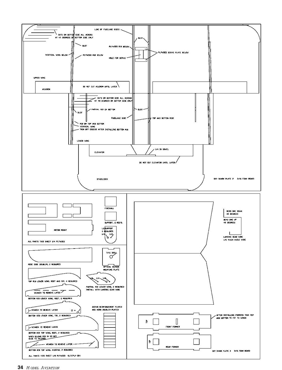
When cutting foam board, keep your blade at roughly 45° while cutting. Don't cut through to the top (opposite) side of the foam board.
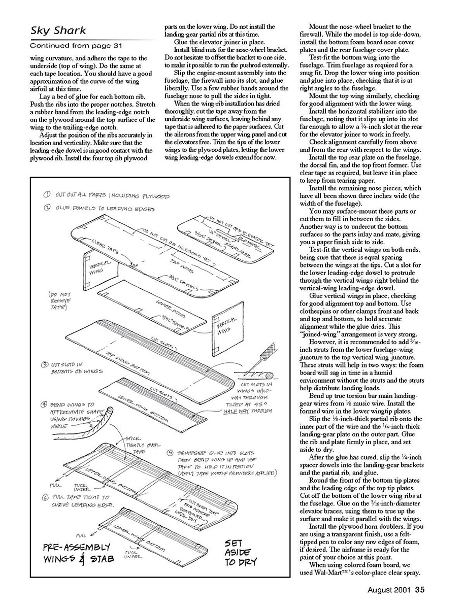
To prepare for gluing dowels to the leading edges of the wings, precut several 1½-inch strips of clear tape and mark regularly spaced positions for the tape to be installed. Once this tape is pressed on, it cannot be removed without tearing paper.
Use five positions for the top wing, three for the bottom wing, and two or three each for other surfaces. Glue all the 3/16-inch leading-edge dowels in place, then set the panels aside to dry thoroughly.
Sometime when you have nothing better to do, reglue the dowels top and bottom to prevent fuel seepage under the paper.
When the servo plates are dry, predrill for the servo screws. When the engine-mount parts are dry, drill for your motor and install the blind nuts.
Taper one side of the fuselage at the rear joint, so only one full thickness of foam board will be available for inserting rudder hinges. Install both fuselage formers, noting top from bottom and front from rear.
Square the formers accurately using a scrap of foam board as a square. When dry, pull the rear fuselage sides together and glue and clamp them, checking for accurate vertical alignment.
Beginning with the lower wing, then following the same steps with the top wing, prebend the curvature of the leading edge by placing the panel on a bench, top side-down and cut side-up.
Pull up on the leading-edge dowel and press into the underside with thumbs until an approximation of the final curve can be developed by pulling the leading edge up.
Place your tape dispenser a distance from the edge of your bench that is equal to the span chord plus two inches. Precut the number of tape strips you will need. Set these strips aside in a handy place.
Work white glue into the wing leading-edge slits with a scrap of foam board. Starting in the center of the wing panel, press a piece of tape tightly around the leading-edge dowel and onto the upper surface of the wing by one inch. Pull the tape tightly toward the trailing edge to form the required bond.
Lay a bed of glue for each bottom rib. Push the ribs into the proper notches. Stretch a rubber band from the leading-edge notch on the plywood around the top surface of the wing to the trailing-edge notch.
Adjust the position of the ribs accurately in location and verticality. Make sure that the leading-edge dowel is in good contact with the plywood rib. Install the four top rib plywood parts on the lower wing. Do not install the landing-gear partial ribs at this time.
Glue the elevator joiner in place.
Install blind nuts for the nose-wheel bracket. Do not hesitate to offset the bracket to one side, to make it possible to run the pushrod externally.
Slip the engine-mount assembly into the fuselage, the firewall into its slot, and glue liberally. Use a few rubber bands around the fuselage nose to pull the sides in tight.
When the wing-rib installation has dried thoroughly, cut the tape away from the underside wing surfaces, leaving behind any tape that is adhered to the paper surfaces. Cut the ailerons from the upper wing panel and cut the elevators free. Trim the tips of the lower wings to the plywood plates, letting the lower wing leading-edge dowels extend for now.
Mount the nose-wheel bracket to the firewall. While the model is top side-down, install the bottom foam board nose cover plates and the rear fuselage cover plate.
Test-fit the bottom wing into the fuselage. Trim fuselage as required for a snug fit. Drop the lower wing into position and glue into place, checking that it is at right angles to the fuselage.
Mount the top wing similarly, checking for good alignment with the lower wing.
Install the horizontal stabilizer into the fuselage, noting that it slips up into its slot far enough to allow a 1/4-inch slot at the rear for the elevator joiner to work in freely.
Check alignment carefully from above and from the rear with respect to the wings.
Install the top rear plate on the fuselage, the dorsal fin, and the top front former. Use clear tape as required, but leave it in place to keep from tearing paper.
Install the remaining nose pieces, which have all been shown three inches wide (the width of the fuselage).
You may surface-mount these parts or cut them to fill in between the sides. Another way is to undercut the bottom surfaces so the parts inlay and mate, giving you a paper-finished side to side.
Test-fit the vertical wings on both ends, being sure that there is equal spacing between the wings at the tips. Cut a slot for the lower leading-edge dowel to protrude through the vertical wings right behind the vertical-wing leading-edge dowel.
Glue vertical wings in place, checking for good alignment top and bottom. Use clothespins or other clamps front and back and top and bottom, to hold accurate alignment while the glue dries. This "joined-wing" arrangement is very strong.
However, it is recommended to add 5/16-inch struts from the lower fuselage-wing juncture to the top vertical wing juncture. These struts will help in two ways: the foam board will sag in time in a humid environment without the struts, and the struts help distribute landing loads.
Bend up true torsion-bar main landing-gear wires from 3/32 music wire. Install the formed wire in the lower wingtip plates. Slip the 1/8-inch-thick partial rib onto the inner part of the wire and the 1/4-inch-thick landing-gear plate on the outer part. Glue the rib and plate firmly in place, and set aside to dry.
After the glue has cured, slip the 1/4-inch spacer dowels into the landing-gear brackets and the partial rib, and glue.
Round the front of the bottom tip plates and the leading edge of the top tip plates. Cut off the bottom of the lower wing ribs at the fuselage. Glue on the 3/16-inch-diameter elevator braces, using them to true up the surface and make it parallel with the wings.
Install the plywood horn doublers. If you are using a transparent finish, use a felt-tipped pen to color any raw edges of foam, if desired. The airframe is ready for the paint of your choice at this point.
When using colored foam board, we used Wal-Mart’s color-place clear spray. It is cheap and seems to be fuelproof. Coat the engine area well for good fuelproofing.
If the model is to be flown conventionally, color the bottom side of all flying surfaces dark. Place celluloid over the sensor view-window openings.
In the prototype we have learned that some momentary autopilot irregularities may come from reflections off of the vertical wings. Paint the inner vertical wing, the top of the bottom wing, and the bottom of the top wing flat black, to reduce the possibility of adverse reflections.
Install horns on all control surfaces. Install wheels using collars for positioning. Go around all edges of the airframe with a sharp, new blade and fine sandpaper, truing and smoothing rough edges. Add any trim desired.
Hinge all control surfaces. Prepare and install all control linkages.
It is very important to set all control throws properly. Ailerons and elevators should move 1/2 inch maximum from neutral up and down; the rudder should move 1 1/2 inches. Set the horns on the farthest-out hole setting.
It is rarely necessary in normal flight to exceed 1/3-stick motion left-right or up-down. The only reason for the excess motion is to overcome the autopilot if the sun is low and it gets to the sensor.
Rig the RC system so the transmitter-stick functions are:
- Left stick fore-aft: throttle
- Right stick fore-aft: elevator (fore is down and aft is up)
- Right stick side-to-side: rudder
- Left stick side-to-side: aileron
Aileron control is not used at all for normal flight. This way the autopilot, at full sensitivity, will be overcome with roughly half-stick motion.
For a real hoot, rig aileron control to work backward, and use it in coordination with rudder when flying to make tighter flat turns.
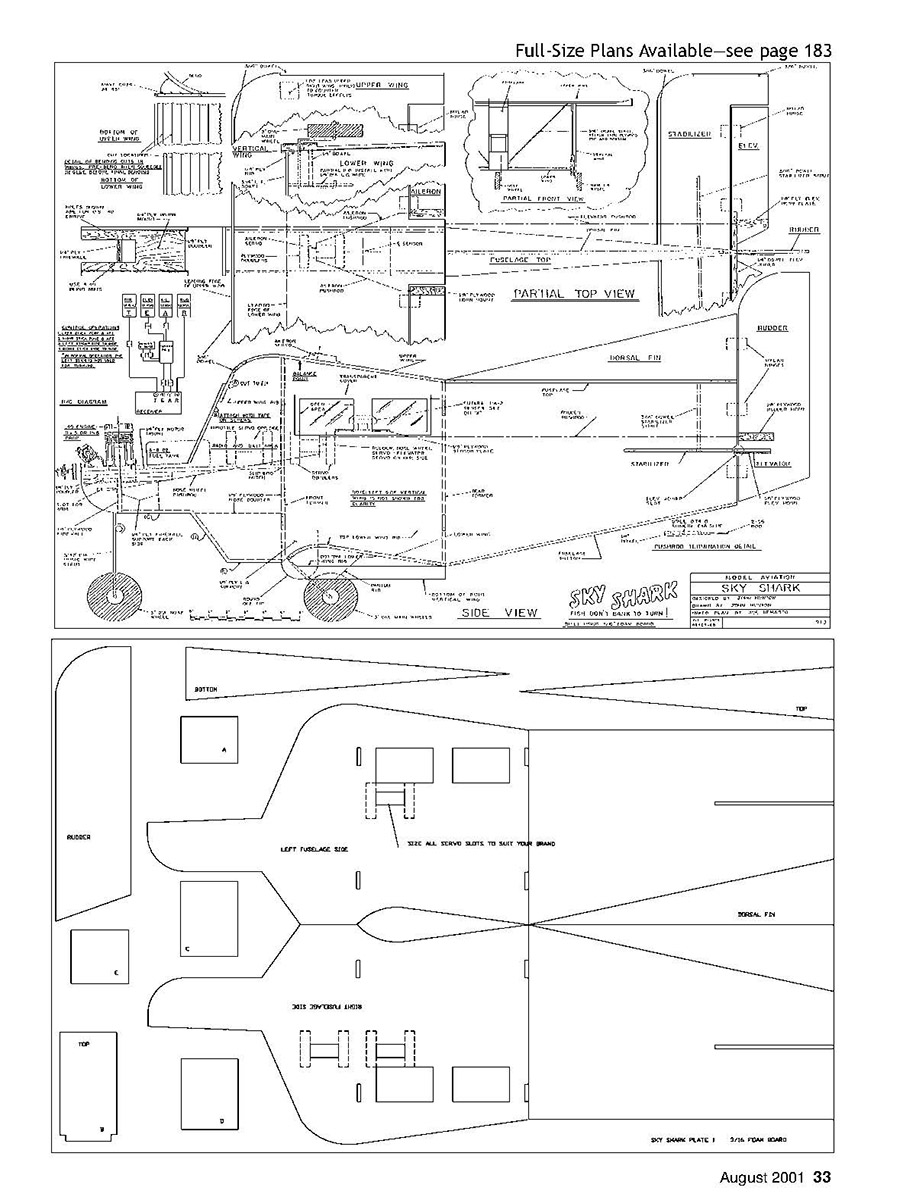
The basic model assembly is complete and ready for engine, fuel tank, and RC-system installation (see diagram on plans). Observe how strong the "joined-wing" configuration is.
After RC installation, check the balance point and add any ballast necessary.
It is essential for success that the model be balanced within 1/4 inch of the location shown with the fuel tank empty. Add the counterweight under the right wingtip.
Flying
You will need a smooth flying surface (closely cropped grass is preferred). You will need approximately 100 feet for taking off. For landing, the longer and wider the reach, the better.
- Perform a range check per RC-system instructions.
- Check engine-idle setting for reliability. (It does not have to be very low with this high-drag model.)
- Test-taxi at partial throttle. Make any adjustments necessary for straight-ahead tracking.
- Recheck everything.
When you're ready to fly, apply full throttle to take off. If the engine sags at any time, shut it down immediately, taxi back, and reset the mixture slightly richer.
When taxiing for takeoff, apply quick jabs of steering to make corrections. Keep the elevator neutral, and the model should take off by itself if it's trimmed properly. On grass you may have to add some up-elevator to get the model into the air, then let off the up-elevator to maintain a shallow climb.
You may steer the model safely as soon as you break ground. (This is a difficult time for conventional models, where the flier tends to correct for torque effects with aileron; the conventional model will often stall and snap-roll to the left.)
Let the model climb on its own until it's 200 or 300 feet high. Turn as required to keep the model in close enough for you to see what is going on.
When you get to a safe height, throttle back and let the model stabilize in level flight at reduced power. Trim the elevator and rudder for level and straight-ahead flight.
Never let the model get downwind from you. It can get out of sight quickly.
Cruise around while you get used to the airplane. It should never be required to go wall-to-wall with the control stick. Keep your control motions minimal (1/3 motion maximum) and your turns wide.
If you run into trouble, let go of the sticks and the model will stabilize in level flight.
Well before the model runs out of fuel (after roughly eight minutes), begin to set up for your landing.
Do ovals around the field, then on a downwind run, reduce power to a safe idle to come down. Be prepared to add power at any time to go around if things are not right.
Plan to land roughly 1/3 of the way down the field. Let the model settle onto the runway. Flaring looks good, but is not necessary for a safe landing.
The beginner should be able to fly competently very quickly with the Sky Shark. Good luck with your model.
Let us know how it goes, and let us know if you have any comments or recommendations for improving the design.
MA
- John Hunton
- 9154 Rixeyville Rd.
- Rixeyville VA 22737
- [email protected]
Materials List
Item - Brand/size - Quantity
- Fome-Cor® boards - 32 x 40 x 3/16 - 3
- Hardwood dowels - 1/4 x 36 - 1
- Hardwood dowels - 3/16 x 36 - 3
- Glue - Elmer's® B-4 ounce - 2
- Clear tape - Scotch®, roll - 1
- Spray adhesive - 3M™ - 1
- Foam tape - 3M™ - 1
- Paint, high gloss - 21st Century® - 1
- Lead weight - 1-ounce - 1
- Epoxy glue - 5-minute - 1
- Lite-Ply - 1/8 x 12 x 24 - 3
- Lite-Ply - 1/4 x 12 x 24 - 2
- Nuts and bolts - 6-32 x 1-inch - 4
- Blades - X-Acto™ - 5
- Control horns - Goldberg - 3
- Pushrods - Du-Bro - 5
- Solder links - Du-Bro - 5
- Music wire - 1/8 K&S - 1
- Collars - 5/32 Goldberg - 2
- Nose wheel - 5/32 Goldberg - 1
- Hinges - Mylar™ - 14
- Celluloid - 8½ x 11 - 1
- Autopilot link - Futaba PA-2 - 1
- RC System - 4-channel, 4 servos - 1
- Engine - .40 - 1
- Propeller - 11 x 5 - 1
- Spinner - 3-inch - 1
- Lite wheels - 3½-inch - 3
- Fuel tank - 6-ounce Sullivan - 1
- Fuel tubing - Goldberg - 1
Final notes
- It is recommended to paint certain surfaces flat black to reduce reflections that can confuse the optical autopilot: inner vertical wing, top of the bottom wing, and bottom of the top wing.
- Balance the model within 1/4 inch of the specified location with the fuel tank empty.
- Keep control motions minimal; normal flight rarely requires more than 1/3-stick input.
Transcribed from original scans by AI. Minor OCR errors may remain.

