
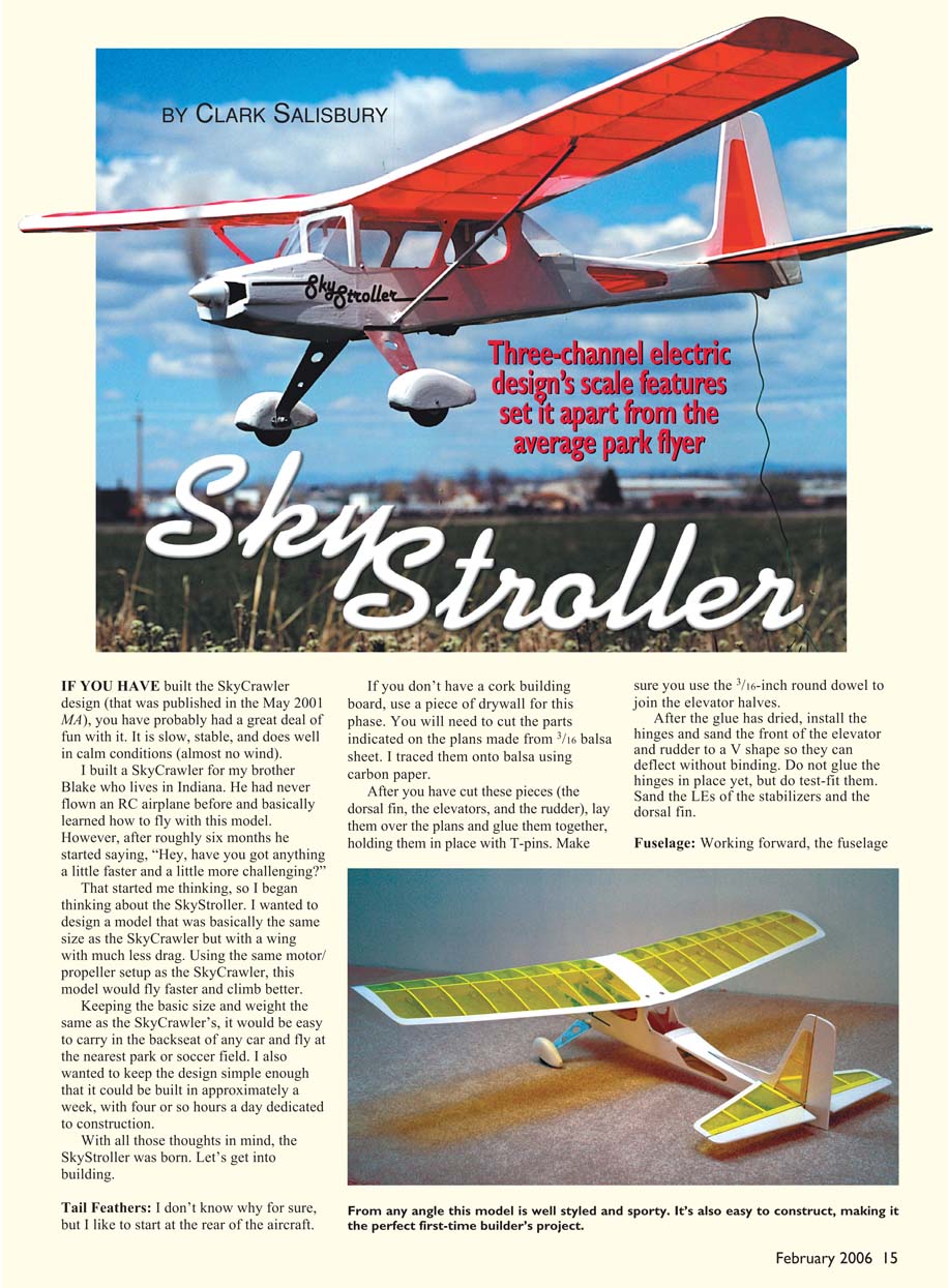
Sky Stroller
By Clark Salisbury
If you have built the SkyCrawler design (published in the May 2001 MA), you have probably had a great deal of fun with it. It is slow, stable, and does well in calm conditions (almost no wind).
I built a SkyCrawler for my brother Blake who lives in Indiana. He had never flown an RC airplane before and basically learned how to fly with this model. However, after roughly six months he started saying, “Hey, have you got anything a little faster and a little more challenging?” That started me thinking, and I began designing the SkyStroller. I wanted a model basically the same size as the SkyCrawler but with a wing that had much less drag. Using the same motor/propeller setup as the SkyCrawler, the SkyStroller would fly faster and climb better. Keeping the basic size and weight the same as the SkyCrawler’s would make it easy to carry in the backseat of any car and fly at the nearest park or soccer field. I also wanted to keep the design simple enough to build in approximately a week, with four or so hours a day dedicated to construction. With all that in mind, the SkyStroller was born.
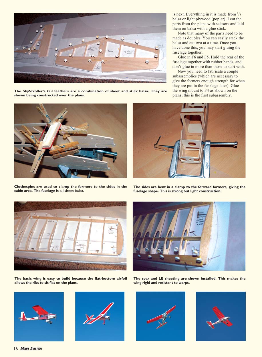
Tail Feathers
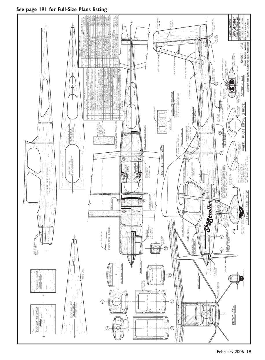
I like to start at the rear of the aircraft. If you don’t have a cork building board, use a piece of drywall for this phase. Cut the parts indicated on the plans from 3/16-inch balsa sheet. I traced them onto balsa using carbon paper. After cutting the dorsal fin, elevators, and rudder, lay them over the plans and glue them together, holding them in place with T-pins. Use the 3/16-inch round dowel to join the elevator halves.
After the glue has dried, install the hinges and sand the front of the elevator and rudder to a V shape so they can deflect without binding. Do not glue the hinges in place yet, but do test-fit them. Sand the leading edges of the stabilizers and the dorsal fin.
Fuselage
Working forward, the fuselage is next. Most parts are made from 1/8-inch balsa or light plywood (poplar). Cut the parts from the plans with scissors and lay them on balsa with a glue stick. Note that many parts need to be made as doubles — you can stack the balsa and cut two at a time.
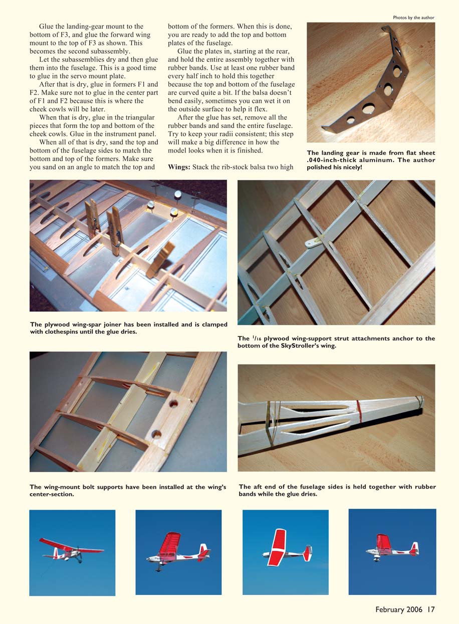
Start gluing the fuselage together by installing F6 and F5. Hold the rear of the fuselage together with rubber bands, and don’t glue in more than those to start. Fabricate a couple of subassemblies to give the formers enough strength for later installation. Glue the wing mount to F4 as shown on the plans — this is the first subassembly.
Glue the landing-gear mount to the bottom of F3, and glue the forward wing mount to the top of F3 as shown; this becomes the second subassembly. Let the subassemblies dry and then glue them into the fuselage. This is a good time to glue in the servo mount plate.
After that dries, glue in formers F1 and F2. Do not glue in the center part of F1 and F2 because this is where the cheek cowls will be later. When dry, glue in the triangular pieces that form the top and bottom of the cheek cowls, and glue in the instrument panel.
When all of that is dry, sand the top and bottom of the fuselage sides to match the top and bottom of the formers. Sand on an angle to match the formers’ contours. You are then ready to add the top and bottom plates of the fuselage.
Glue the plates in, starting at the rear, and hold the entire assembly together with rubber bands. Use at least one rubber band every half inch because the top and bottom of the fuselage are curved. If the balsa doesn't bend easily, wetting the outside surface can help it flex.
After the glue has set, remove all the rubber bands and sand the entire fuselage. Try to keep your radii consistent; this step will make a big difference in how the model looks when finished.
Wings
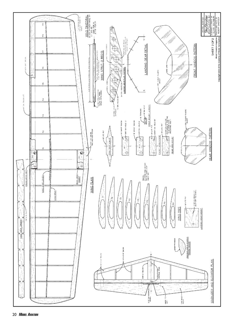
Stack the rib-stock balsa two high and cut all the wing ribs. Do the same with the light plywood to cut the wing spars (you only have to cut one wing joiner). Then cut the wingtips.
I traced the last rib, R9, onto a 1-inch-square balsa block to cut the wingtips. You can sand the balsa block to a 45° angle or cut it with a scroll saw to that angle (from front to rear). Make sure you create a left and a right wingtip when doing this 45° cut. When cutting on the angle, it is easiest to put the scrap part of the balsa block back on the wingtip you cut out earlier to help maintain the shape.
Begin gluing the wing: glue the nine ribs to the 1/4-inch-diameter balsa dowel at the front and the 3/4-inch TE at the rear. Make sure you are creating a left and a right wing. Lay the ribs over the plans and make sure they are exact.
After this has dried, install the wing spar through the middle of the rib holes. If cut accurately, it will rotate up into position; hold it with pins. You can also glue in the 1/32-inch sheeting at the top of the LE at this time.
To join the wing halves, set the dihedral angle and glue in the wing joiner, holding it in place with clothespins or small clamps. For a lot of dihedral (7°), place 2-3/8-inch spacers under the R9 ribs on both wing ends while the middle of the wing is held flat on the table. For minimal dihedral, use a couple of 2 x 4s cut to 6-inch lengths under the R9 ribs; the 2 x 4 is 1-1/2 inches thick, which will give approximately 4° of dihedral. Less dihedral makes the airplane a bit less stable but more responsive to rudder control.
At the same time the wing joiners are added, glue a short piece of 1/4-inch-diameter balsa dowel at the LE of the wing and a short piece of 3/4-inch TE to the rear edge of the wing at the center.
Glue in the two plywood wing mounts at the front and rear of the wing. Glue in the upper balsa wing mounts that have the clearance holes. When dry, test-fit the wing on top of the fuselage. Sand the upper balsa wing mounts to the shape of the wing and sand the rest of the wing.
Add the nylon mounting bolts by drilling through the plywood wing mounts and drilling and tapping the holes in the top of the fuselage to #10-32. Drill the holes in the wing to 7/32 inch diameter. With the wing on the fuselage, add the wing-strut mounts.
Depending on the amount of dihedral, the wing struts will be longer or shorter. The drawing shows struts for the maximum dihedral amount (7°). Make the wing struts, slot the ends to allow for the short threaded rods, and epoxy the threaded rods in place. Adhere the wing-strut mounts in the fuselage and to the wings, making sure the mounts are glued at the same angle as the struts.
Note: the plywood wing-spar joiner is installed and clamped with clothespins until the glue dries. The 1/16-inch plywood wing-support strut attachments anchor to the bottom of the wing. The wing-mount bolt supports are installed at the wing’s center section.
Wheel Pants
The wheel pants are made mostly from balsa, with the inside wall from light plywood. Cut the balsa and the plywood to the pattern shown on the drawing. When the wood is glued together, make a right and a left wheel pant (determined by the side to which you glue the plywood).
Sand the wheel pants until they have a smooth shape, but don't sand so much that you sand through the wall. Slot the end of the 1/8-inch-diameter axles so a screwdriver can be used when installing the wheels in the wheel pants. The detail drawing shows how it all goes together.
You will probably have to drill the wheels to a 1/8-inch diameter to fit the axle. Do this on a drill press, if possible, to keep the hole straight. Make sure the wheels turn freely before tightening the elastic stop nuts on the axle.
Mount the landing gear to the fuselage using #8 wood screws. The landing gear is made from flat sheet .040-inch-thick aluminum; polish as desired.
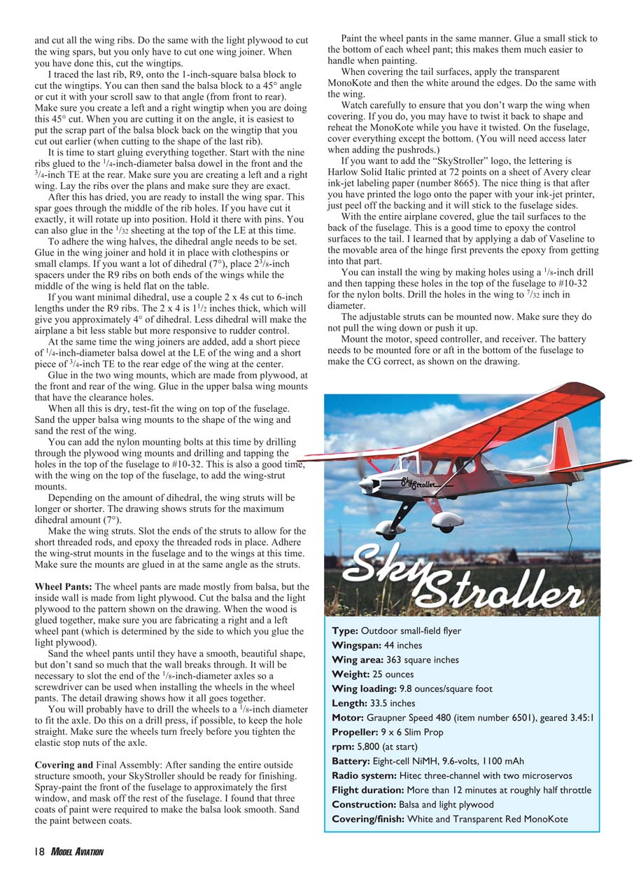
Covering and Final Assembly
After sanding the entire outside structure smooth, the SkyStroller should be ready for finishing. Spray-paint the front of the fuselage to approximately the first window, and mask off the rest of the fuselage. Three coats of paint were required to make the balsa look smooth; sand the paint between coats.
Paint the wheel pants in the same manner. Glue a small stick to the bottom of each wheel pant to make them easier to handle while painting.
When covering the tail surfaces, apply the transparent MonoKote and then the white around the edges. Do the same with the wing. Watch carefully to ensure you don't warp the wing when covering; if you do, you may need to twist it back to shape and reheat the MonoKote while twisted. On the fuselage, cover everything except the bottom (you will need access later when adding the pushrods).
If you want to add the "SkyStroller" logo, the lettering is Harlow Solid Italic printed at 72 points on Avery clear ink-jet labeling paper (number 8665). After printing the logo with your ink-jet printer, peel off the backing and it will stick to the fuselage sides.
With the entire airplane covered, glue the tail surfaces to the back of the fuselage. This is a good time to epoxy the control surfaces to the tail. Apply a dab of Vaseline to the movable area of the hinge first to prevent epoxy from getting into that part.
Install the wing by making holes with a 1/8-inch drill and then tapping the holes in the top of the fuselage to #10-32 for the nylon bolts. Drill the holes in the wing to 7/32 inch diameter. Mount the adjustable struts and make sure they do not pull the wing down or push it up.
Mount the motor, speed controller, and receiver. You will need two 2.5mm x 10mm screws and washers to mount the motor/gearbox. The battery needs to be mounted fore or aft in the bottom of the fuselage to make the CG correct, as shown on the drawing.
After cutting the window pattern and bending it, mount the windows with #2 x 3/8-inch-long wood screws. The drawing shows backup plywood pieces (1/4 inch square) to mount the windows; glue these in first so the screws can attach to them.
Flying
I took my SkyStroller to the local flying field for its maiden flight. I had my good friend Dave Stuart fly it for the first time.
I hand-launched the model into a slight breeze, and it took off at roughly a 20° climb. Dave slowed it with the speed control when it reached a couple hundred feet, and it descended so I could take photos. After about five minutes of pictures, Dave let me fly. I was pleased with the responsiveness.
The SkyStroller flies great at approximately half speed, but it doesn't quite loop at half speed. Loops are simple to do at full speed. The airplane is easy to see in the sky; it is quite a sight with its transparent covering. Dave tried to stall the model, but it only mushed down with no tip-stalling tendency.
Landing was routine, although the small wheels and wheel pants favor hard-surface landings; Dave landed on asphalt. For grass landings, use wheels approximately 2.5 inches in diameter with no wheel pants. If you like the looks of wheel pants, you can keep them and switch to larger wheels for grass landings.
The SkyStroller is capable of a brisk "stroll" through the sky at 25 mph or faster. I suggest this as a second airplane for anyone who has experience flying RC. Have fun!
MA
Clark Salisbury [email protected]
Transcribed from original scans by AI. Minor OCR errors may remain.

