
Skyfire 4.05
by Larry Renger
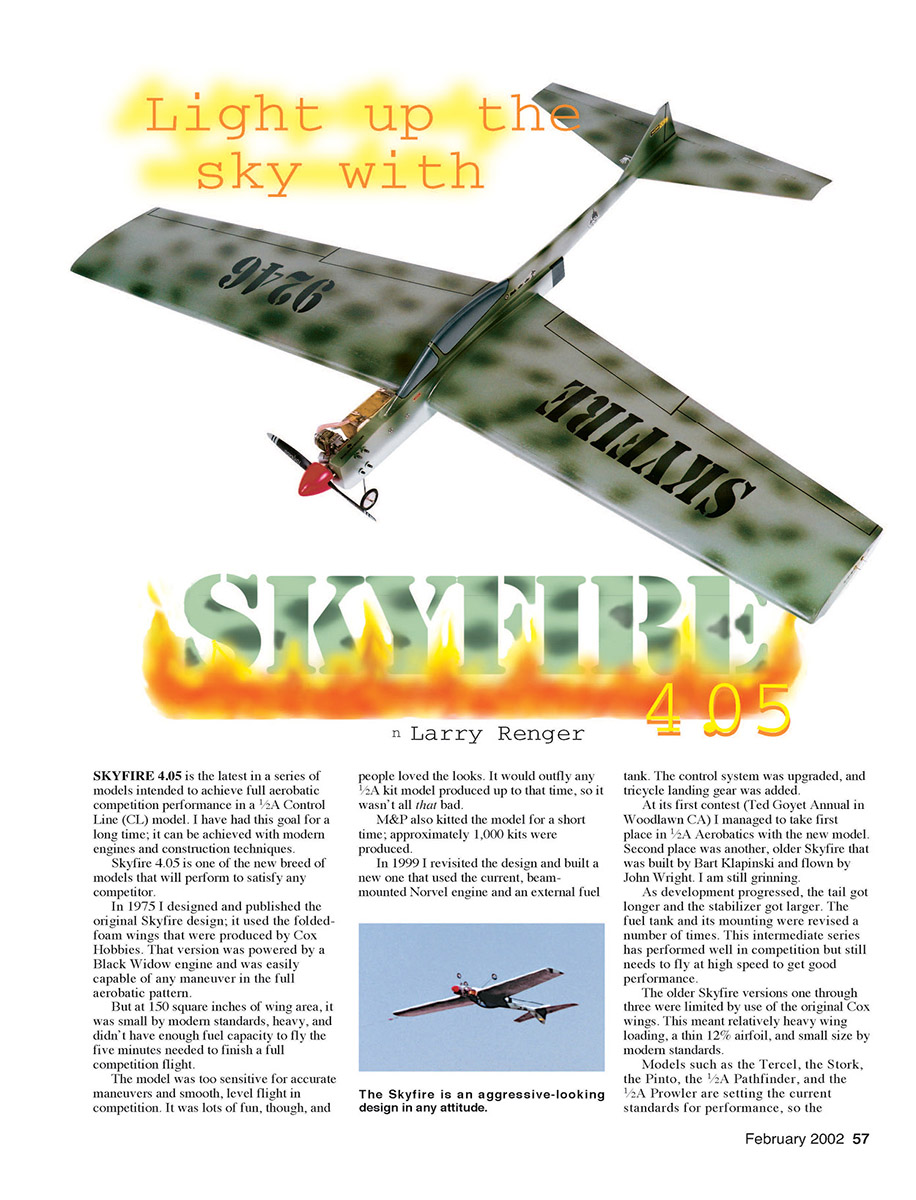
SKYFIRE 4.05 is the latest in a series of models intended to achieve full aerobatic competition performance in a 1/2A Control Line (CL) model. I have had this goal for a long time; it can be achieved with modern engines and construction techniques.
Skyfire 4.05 is one of the new breed of models that will perform to satisfy any competitor.
In 1975 I designed and published the original Skyfire design; it used the folded-foam wings that were produced by Cox Hobbies. That version was powered by a Black Widow engine and was easily capable of any maneuver in the full aerobatic pattern.
But at 150 square inches of wing area, it was small by modern standards, heavy, and didn't have enough fuel capacity to fly the five minutes needed to finish a full competition flight.
The model was too sensitive for accurate maneuvers and smooth, level flight in competition. It was lots of fun, though, and people loved the looks. It would outfly any 1/2A kit model produced up to that time, so it wasn't all that bad.
M&P also kitted the model for a short time; approximately 1,000 kits were produced.
In 1999 I revisited the design and built a new one that used the current, beam-mounted Norvel engine and an external fuel tank. The control system was upgraded, and tricycle landing gear was added.
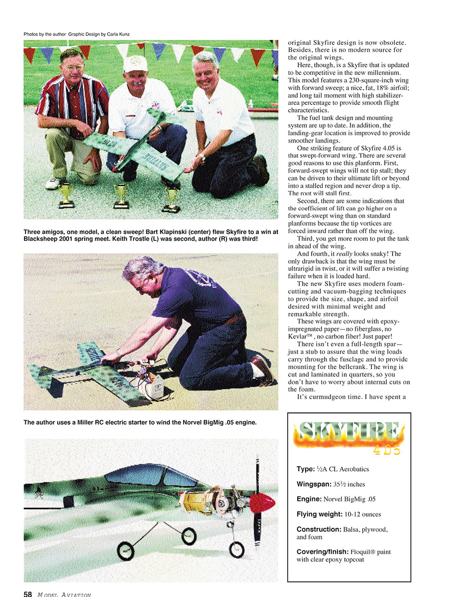
At its first contest (Ted Goyet Annual in Woodlawn CA) I managed to take first place in 1/2A Aerobatics with the new model. Second place was another, older Skyfire that was built by Bart Klapinski and flown by John Wright. I am still grinning.
As development progressed, the tail got longer and the stabilizer got larger. The fuel tank and its mounting were revised a number of times. This intermediate series has performed well in competition but still needs to fly at high speed to get good performance.
The older Skyfire versions one through three were limited by use of the original Cox wings. This meant relatively heavy wing loading, a thin 12% airfoil, and small size by modeller standards.
Models such as the Tercel, the Stork, the Pinto, the 1/2A Pathfinder, and the 1/2A Prowler are setting the current standards for performance, so the original Skyfire design is now obsolete. Besides, there is no modern source for the original wings.
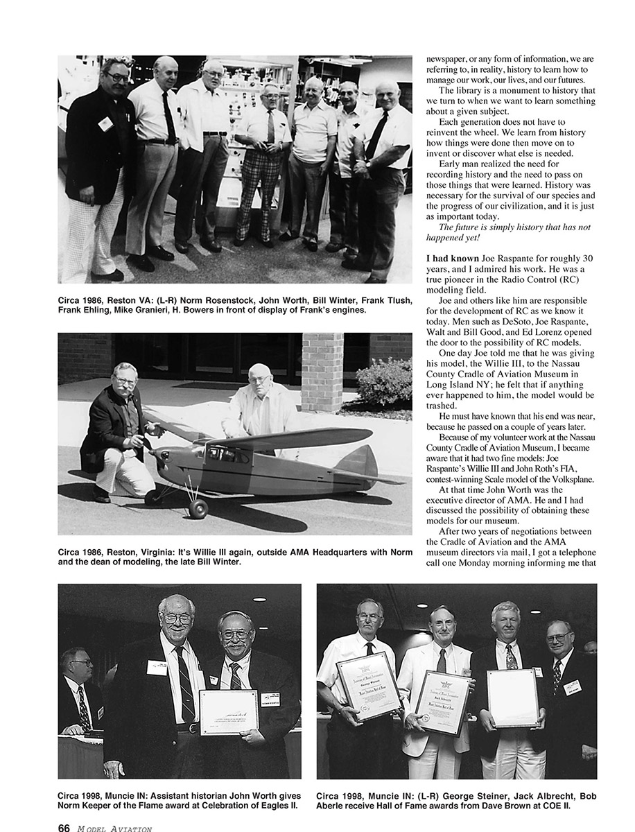
Here, though, is a Skyfire that is updated to be competitive in the new millennium. This model features a 230-square-inch wing with forward sweep; a nice, fat, 18% airfoil; and long tail moment with high stabilizer-area percentage to provide smooth flight characteristics.
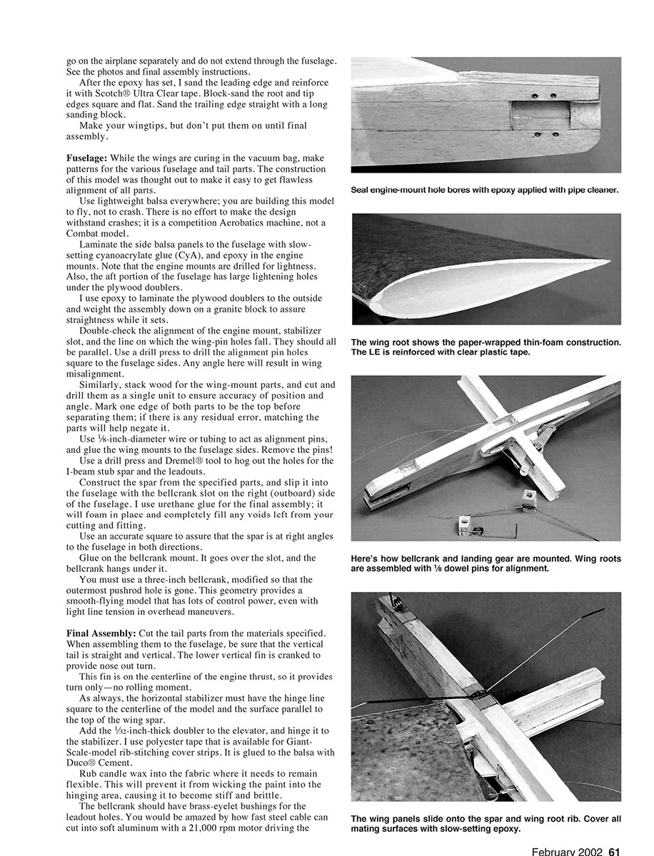
The fuel tank design and mounting system are up to date. In addition, the landing-gear location is improved to provide smoother landings.
One striking feature of Skyfire 4.05 is that swept-forward wing. There are several good reasons to use this planform. First, forward-swept wings will not tip stall; they can be driven to their ultimate lift or beyond into a stalled region and never drop a tip. The root will stall first.
Second, there are some indications that the coefficient of lift can go higher on a forward-swept wing than on standard planforms because the tip vortices are forced inward rather than off the wing.
Third, you get more room to put the tank in ahead of the wing.
And fourth, it really looks snaky! The only drawback is that the wing must be ultrarigid in twist, or it will suffer a twisting failure when it is loaded hard.
The new Skyfire uses modern foam-cutting and vacuum-bagging techniques to provide the size, shape, and airfoil desired with minimal weight and remarkable strength.
These wings are covered with epoxy-impregnated paper—no fiberglass, no Kevlar, no carbon fiber! Just paper!
There isn't even a full-length spar—just a stub to assure that the wing loads carry through the fuselage and to provide mounting for the bellcrank. The wing is cut and laminated in quarters, so you don't have to worry about internal cuts on the foam.
It's curmudgeon time. I have spent a lot of time, effort, broken airplanes, and engines finding things that don't work. Along the way I have learned what does work well for me. This model, with all its features, avoids the pitfalls I have found so far.
Be very sure of what you are doing if you change things. I will happily answer questions and discuss ideas via E-mail at [email protected].
Oh, the name? Why the 4.05? This is version 4, for a nominal .05-cubic-inch-displacement engine. And oh yes, there are drawings completed for a Skyfire 4.40 ...
Enough talk; let's build!
CONSTRUCTION
Wing: Start with the wing because there are a few days of wing panels sitting in the vacuum-bagging system ahead of you. You can build the other parts while the wing panels are curing.
Many modelers don't have foam-cutting capability, but services advertised in this and in other magazines can easily do the job for you. Similarly, vacuum-bagging can be bypassed by using a soft foam sheet over the panel with a board and lots of weights.
The weights provide pressure, and the board and soft foam distribute it evenly, as if using a vacuum system. (You need approximately 200 pounds of weight for a 100-square-inch panel to equal a 2 psi [pounds per square inch] pressure drop, though.)
The guides for hot-wire cutting are provided on the plans. I use the Tekoa foam-cutting machine; it works extremely well and accurately. Follow the directions, and you will get great cuts.
I also included root and tip airfoils if you use a different system. The foam looks thin, but it is adequate, and you have more weight to spare on a 1/2A competition model.
Be sure you are working on a flat work surface; any twist in your workbench is going to be doubled in the wings, and these wings cannot be warped back straight!
The foam to use is the blue or pink insulating material. The density should be two pounds per cubic foot or less. I have used the white, beaded foam, but it leaves a lumpy outer surface after bagging.
Save the top and bottom scrap pieces for use as a support while sanding the outer surface smooth and for fixtures when bagging and assembling the panels.
Cut all four shells. I make a long sanding block with wallboard sanding screen glued to it for surfacing the foam. This stuff is far less likely to pick up junk and make a groove in the surface. Finish of the inner surface of the shell is of no importance; leave it as cut.
Wrap the bottom scrap piece with Saran Wrap, then use that as a support for the shell when laminating the paper covering on. Cut a piece of white Kraft paper somewhat oversize. Cut a piece of Mylar to match the wing, and thoroughly wax both sides of it.
I use Eze-lam epoxy from Aerospace Composites for my bagging operation, and its pump and bag system.
The laminating process is simple. Mix the epoxy per instructions, then cut it 20% with denatured alcohol. Brush the mix onto the outside surface of the paper, and lay that down on the Mylar sheet.
Brush epoxy onto the inside surface of the paper, and let the whole thing sit for a couple of minutes.
Even the coating so it is noticeably wet everywhere, with no puddles of epoxy. This assures that the paper will be thoroughly soaked but without excessive weight. There is no need to put epoxy directly on the foam.
Assemble your sandwich, put it on the support scrap piece, and into the vacuum bag. I do one-quarter of the wing at a time. When the skins have hardened, trim the paper flush to the foam.
Use the upper scrap from cutting the foam shells as a nest when joining the wing quarters. I put one panel in the nest, weight it down, then epoxy the mating panel to it.
Use masking tape to hold the two quarters together. Be sure you do this on a flat surface, or you will be locking a warp into the panels that cannot be removed.
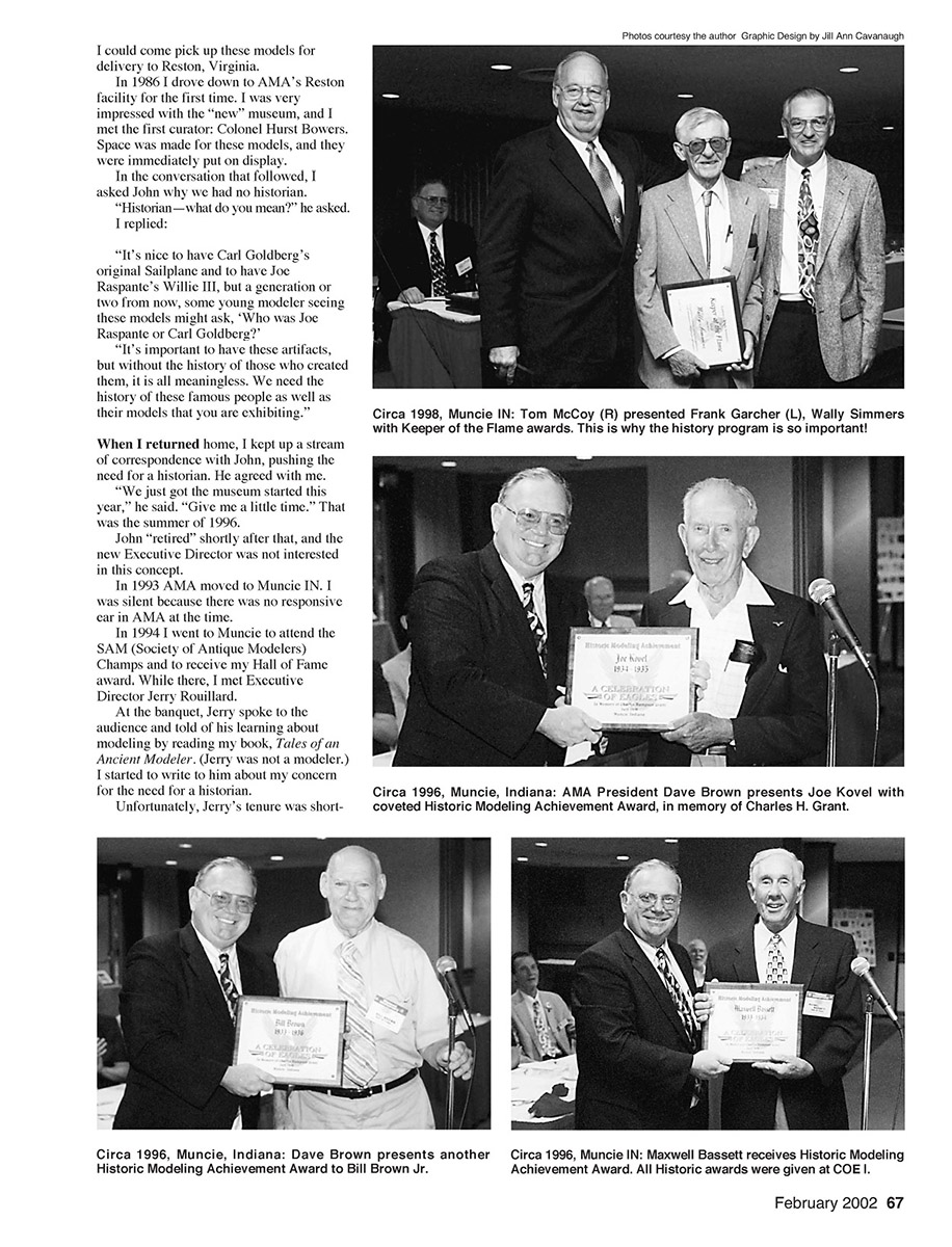
You are only making wing halves. They go on the airplane separately and do not extend through the fuselage. See the photos and final assembly instructions.
After the epoxy has set, I sand the leading edge and reinforce it with Scotch Ultra Clear tape. Block-sand the root and tip edges square and flat. Sand the trailing edge straight with a long sanding block.
Make your wingtips, but don't put them on until final assembly.
Fuselage: While the wings are curing in the vacuum bag, make patterns for the various fuselage and tail parts. The construction of this model was thought out to make it easy to get flawless alignment of all parts.
Use lightweight balsa everywhere; you are building this model to fly, not to crash. There is no effort to make the design withstand crashes; it is a competition Aerobatics machine, not a Combat model.
Laminate the side balsa panels to the fuselage with slow-setting cyanoacrylate glue (CyA), and epoxy in the engine mounts. Note that the engine mounts are drilled for lightness. Also, the aft portion of the fuselage has large lightening holes under the plywood doublers.
I use epoxy to laminate the plywood doublers to the outside and weight the assembly down on a granite block to assure straightness while it sets.
Double-check the alignment of the engine mount, stabilizer slot, and the line on which the wing-pin holes fall. They should all be parallel. Use a drill press to drill the alignment pin holes square to the fuselage sides. Any angle here will result in wing misalignment.
Similarly, stack wood for the wing-mount parts, and cut and drill them as a single unit to ensure accuracy of position and angle. Mark one edge of both parts to be the top before separating them; if there is any residual error, matching the parts will help negate it.
Use 1/8-inch-diameter wire or tubing to act as alignment pins, and glue the wing mounts to the fuselage sides. Remove the pins!
Use a drill press and Dremel tool to hog out the holes for the I-beam stub spar and the leadouts.
Construct the spar from the specified parts, and slip it into the fuselage with the bellcrank slot on the right (outboard) side of the fuselage. I use urethane glue for the final assembly; it will foam in place and completely fill any voids left from your cutting and fitting.
Use an accurate square to assure that the spar is at right angles to the fuselage in both directions.
Glue on the bellcrank mount. It goes over the slot, and the bellcrank hangs under it.
You must use a three-inch bellcrank, modified so that the outermost pushrod hole is gone. This geometry provides a smooth-flying model that has lots of control power, even with light line tension in overhead maneuvers.
Final Assembly
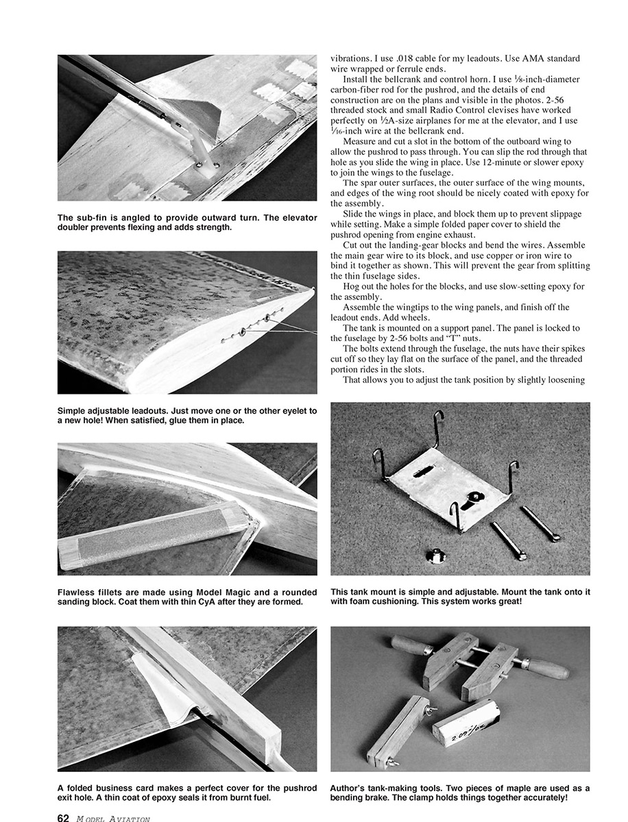
Cut the tail parts from the materials specified. When assembling them to the fuselage, be sure that the vertical tail is straight and vertical. The lower vertical fin is cranked to provide nose out turn.
This fin is on the centerline of the engine thrust, so it provides turn only—no rolling moment.
As always, the horizontal stabilizer must have the hinge line square to the centerline of the model and the surface parallel to the top of the wing spar.
Add the 1/32-inch-thick doubler to the elevator, and hinge it to the stabilizer. I use polyester tape that is available for Giant-Scale-model rib-stitching cover strips. It is glued to the balsa with Duco Cement.
Rub candle wax into the fabric where it needs to remain flexible. This will prevent it from wicking the paint into the hinging area, causing it to become stiff and brittle.
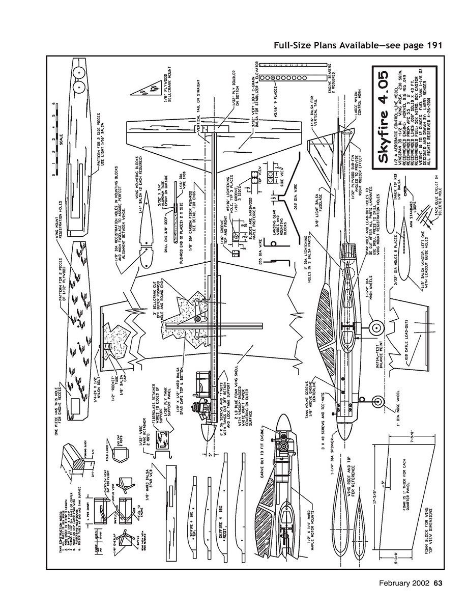
The bellcrank should have brass-eyelet bushings for the leadout holes. You would be amazed by how fast steel cable can cut into soft aluminum with a 21,000 rpm motor driving the vibrations. I use .018 cable for my leadouts. Use AMA standard wire wrapped or ferrule ends.
Install the bellcrank and control horn. I use 1/8-inch-diameter carbon-fiber rod for the pushrod, and the details of end construction are on the plans and visible in the photos. 2-56 threaded stock and small Radio Control clevises have worked perfectly on 1/2A-size airplanes for me at the elevator, and I use 1/16-inch wire at the bellcrank end.
Measure and cut a slot in the bottom of the outboard wing to allow the pushrod to pass through. You can slip the rod through that hole as you slide the wing in place. Use 12-minute or slower epoxy to join the wings to the fuselage.
The spar outer surfaces, the outer surface of the wing mounts, and edges of the wing root should be nicely coated with epoxy for the assembly.
Slide the wings in place, and block them up to prevent slippage while setting. Make a simple folded paper cover to shield the pushrod opening from engine exhaust.
Cut out the landing-gear blocks and bend the wires. Assemble the main gear wire to its block, and use copper or iron wire to bind it together as shown. This will prevent the gear from splitting the thin fuselage sides.
Hog out the holes for the blocks, and use slow-setting epoxy for the assembly.
Assemble the wingtips to the wing panels, and finish off the leadout ends. Add wheels.
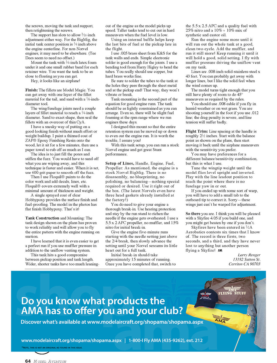
The tank is mounted on a support panel. The panel is locked to the fuselage by 2-56 bolts and "T" nuts.
The bolts extend through the fuselage, the nuts have their spikes cut off so they lay flat on the surface of the panel, and the threaded portion rides in the slots.
That allows you to adjust the tank position by slightly loosening the nuts and sliding the panel forward or back. Bolt the panel down securely when satisfied.
Tank Construction and Mounting
The tank design shown on the plan has proven to work reliably and will allow you to fly the entire pattern with the engine running on suction.
I have learned that it is even easier to get a perfect run if you use muffler pressure in addition to the uniflow venting system.
This tank hits a good compromise between pickup position and tank length. Wider, shorter tanks have too much leaning-out of the engine as the model picks up speed. Taller tanks tend to cut out in hard maneuvers when the fuel level is low.
Using an internal baffle helps keep the last bits of fuel at the pickup late in the flight.
I use .005 brass sheet from K&S for the tank walls and ends. Simple electronic solder is good enough for the joints. I use a binding tool from Harry Higley to bend the tubes. You really should use copper, but hard brass works fine.
Be sure to solder the tubes to the tank at the holes they pass through the sheet metal and at the pickup end! That way, they won't vibrate or break.
Tank-mounting is the second part of the equation for good engine runs. The tank should be as lightly constrained as you can arrange. Even so, there will be slight fuel foaming at the rpm range where we run engines these days.
I designed this mount so that the entire retention system can be moved up or down to even out the engine run. It is worth the trouble, I assure you!
With this tank setup, you can run a stock Norvel engine and get great Stunt performance.
Setup of Lines, Handle, Engine, Fuel, Propeller
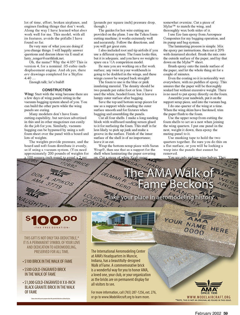
As mentioned, the engine is a stock Norvel BigMig. There is no disassembly, no blueprinting, no polishing, no balancing—nothing special required or desired. Use it right out of the box. (The latest Norvels even have three head gaskets already installed at the factory!)
You do need to give your engine a thorough break-in. Use hearing protection and stay by the run stand to richen the needle if the engine gets overheated. I use a 5.5 x 2 APC propeller, no muffler, and 15% nitro for initial break-in.
Give the engine five-minute runs starting with the needle setting just above the 2/4 break, then slowly advance the setting until your Norvel screams its little heart out for a full tank.
Initial break-in should take approximately 15 minutes of running. Once you have completed that, switch to the 5.5 x 2.5 APC and a quality fuel with 25% nitro and a 10% + 10% mix of synthetic and castor oil.
Run the engine some more until it will run out the whole tank at a good, clean two-cycle. Add the muffler, and run it still more! Keep running it until it will hold a good, solid setting. I fly with muffler pressure driving the uniflow vent on my tank.
Lines are .008-inch solid-stainless-steel x 43 feet. You can probably get away with longer lines, but I like the solid feel when the wind comes up.
The model turns tight enough that you still have plenty of room to do 45° maneuvers as required by the rules.
You should use .008 cable if you fly in humid weather or on wet grass. You are shooting yourself in the foot if you use .012 line; the drag penalty is severe, and line tension will suffer badly.
Flight Trim
Line spacing at the handle is roughly 2½ inches. Start with the balance point as shown on the plans, then start moving it back until the airplane maneuvers with the sensitivity you prefer.
You may have preferences for a different balance/sensitivity combination, but this is what I use.
Tune the wingtip weight until the model flies level upright and inverted. Play with the line leadout position to reach the point where there is no fuselage yaw in or out.
If you end up with some sort of warp, you will have to add a small tab to the outboard tip to correct it. Sorry—these wings just can't be warped for adjustment.
So there you are. I think you will be pleased with a Skyfire 4.05 if you build one, and you might get beaten by one if you don't.
Skyfires have been entered in 1/2A Aerobatics contests six times that I know of. The record is three firsts, two seconds and a third, and they have never lost to anything but another person flying a Skyfire!
Larry Renger 13182 Sutton St. Cerritos CA 90703
Transcribed from original scans by AI. Minor OCR errors may remain.

