
SkySkimmer - 2015/05
by Clark Salisbury
BUILD YOUR OWN WATERPLANE
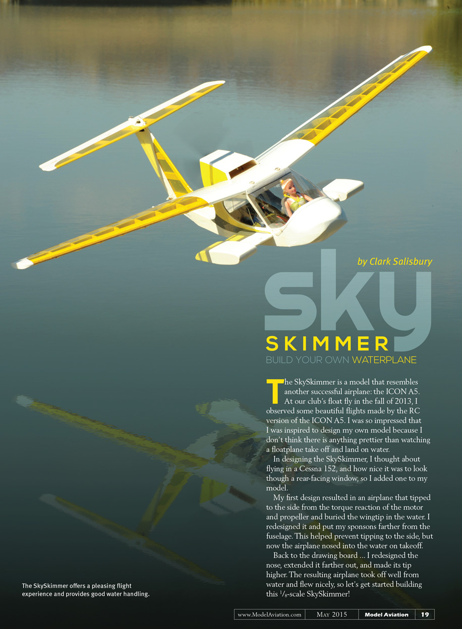
The SkySkimmer is a model that resembles another successful airplane: the ICON A5. At our club’s float fly in the fall of 2013, I observed some beautiful flights made by the RC version of the ICON A5. I was so impressed that I was inspired to design my own model because I don’t think there is anything prettier than watching a floatplane take off and land on water.
In designing the SkySkimmer, I thought about flying in a Cessna 152, and how nice it was to look through a rear-facing window, so I added one to my model.
My first design resulted in an airplane that tipped to the side from the torque reaction of the motor and propeller and buried the wingtip in the water. I redesigned it and put my sponsons farther from the fuselage. This helped prevent tipping to the side, but now the airplane nosed into the water on takeoff.
Back to the drawing board. I redesigned the nose, extended it farther out, and made its tip higher. The resulting airplane took off well from water and flew nicely, so let’s get started building this 1/8-scale SkySkimmer!
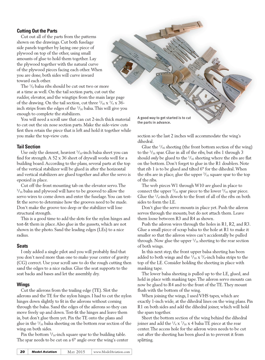
Cutting Out the Parts
Cut out all of the parts from the patterns shown on the drawings. Cut both fuselage side panels together by laying one piece of plywood on top of the other, using small amounts of glue to hold them together. Lay the plywood together with the natural curve of the plywood pieces facing each other. When you are done, both sides will curve inward toward each other.
The 1/8" balsa ribs should be cut out two or more at a time as well. On the tail section parts, cut out the rudder, elevator, and the wingtips from the main large page of the drawing. On the tail section, cut three 3/16" x 3/4" x 36" strips from the edges of the 3/16" balsa. This will give you enough to complete the stabilizers.
You will need a scroll saw that can cut 2" thick material to cut out the six nose section parts. Make the side-view cuts first, then retain the piece that is left and hold it together while you make the top-view cuts.
Tail Section
Use only the densest, heaviest 3/16" balsa sheet you can find for strength. A 52" x 36" sheet of drywall works well for a building board. According to the plans, several parts at the top of the vertical stabilizer will be glued in after the horizontal and vertical stabilizers are glued together and after the servo is epoxied in place.
Cut off the front mounting tab on the elevator servo. The 3/16" balsa and plywood will have to be grooved to allow the servo wires to come down and enter the fuselage. You can test-fit the servo to determine how the grooves need to be made. Don't make the groove too deep or the stabilizer will lose structural strength.
This is a good time to add the slots for the nylon hinges and test-fit them in place. Also glue in the gussets, which are not shown in the photo. Sand the leading edges (LEs) to a nice radius.
Seats
I only added a single pilot and you will probably find that you don't need more than one to make your center of gravity (CG) correct. Use your scroll saw to do the rough cutting then sand the edges to a nice radius. Glue the seat supports to the seat backs and bases and let the assembly dry.
Wings
Cut the ailerons from the trailing edge (TE). Slot the ailerons and the TE for the nylon hinges. I had to cut the nylon hinges down slightly to fit in the ailerons without coming through the balsa. Sand the edges of the ailerons so they can move freely up and down. Test-fit the hinges and leave them in, but don't glue them yet.
Pin the TE onto the plans and glue in the 1/16" balsa sheeting on the bottom rear section of the wing on both sides.
Pin the bottom 3/16" square spar to the building table. The spar needs to be cut on a 6° angle over the wing's center section so the last 2" will accommodate the wing's dihedral.
Glue the 1/16" sheeting (the front bottom section of the wing) to the 3/16" spar. Glue in all of the ribs, but ribs 1 through 3 should only be glued to the 1/16" sheeting where the ribs are flat on the bottom. Don't forget to glue in the R1 doublers. Note that rib 1 is to be glued and tilted 6° for the dihedral. When the ribs are in place, glue the upper 3/16" square spar to the top of the ribs.
The web pieces W1 through W10 are glued in place to connect the upper 3/16" spar piece to the lower 3/16" spar piece. Glue the 1/4" dowels to the front of all of the ribs on both sides to form the LE.
Don't glue the servo mounts in place yet. Push the aileron servos through the mounts, but do not attach them. Leave them loose between R3 and R4 as shown.
Push the aileron wires through the holes in R1, R2, and R3. Glue a small piece of scrap balsa to the hole at R1 to make it smaller so that the aileron wires can't accidentally be pulled through. Now glue the upper 1/16" sheeting to the rear section of both wings.
In this next step, the front upper balsa sheeting has been added to both wings and the 1/16" x 3/4" balsa strips to the top of the LE. Consider holding the sheeting in place with masking tape.
The lower balsa sheeting is pulled up to the LE, glued, and held in place with masking tape. The aileron servo mounts can now be glued to R4 and to the front of the TE. They mount flush with the bottom of the wing.
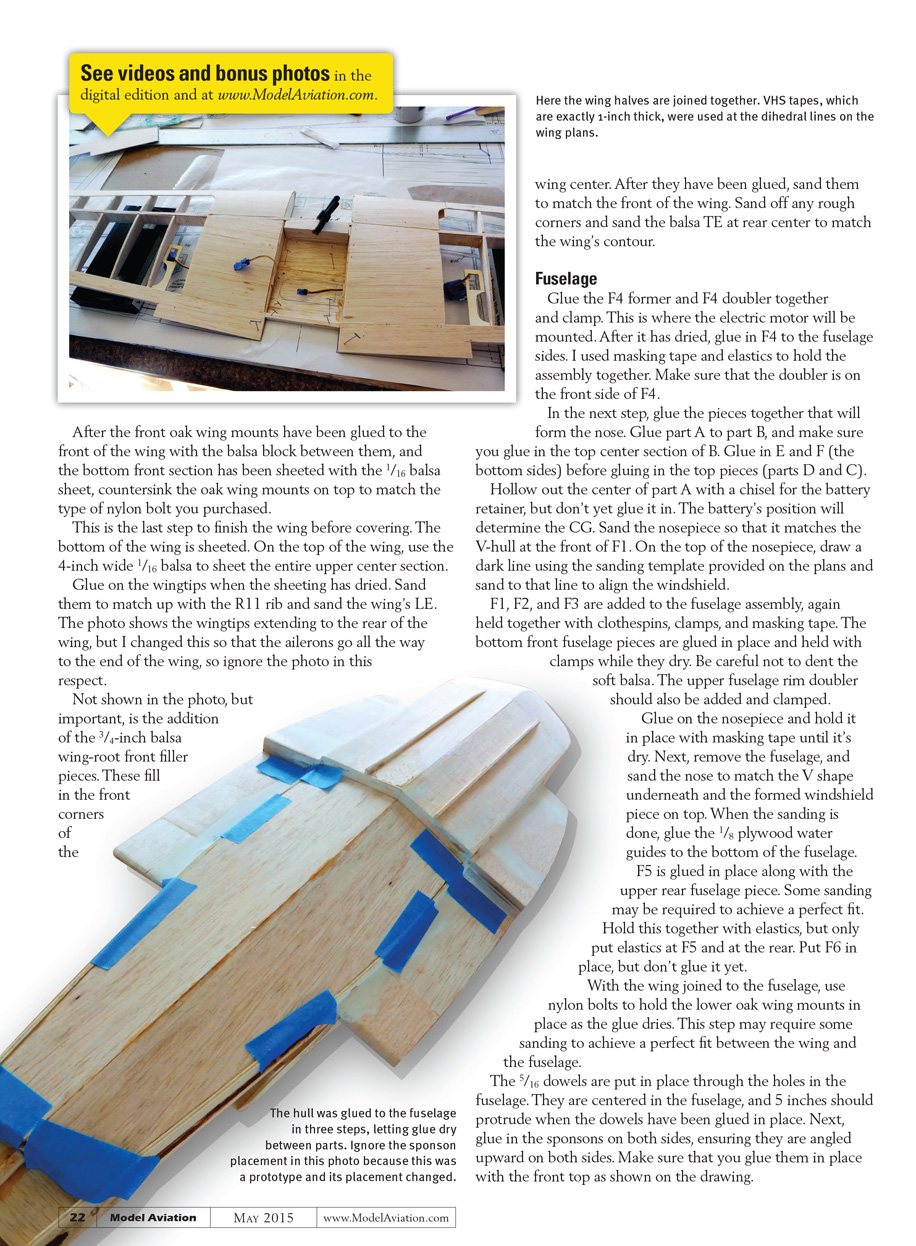
When joining the wings, I used VHS tapes, which are exactly 1-inch wide, at the dihedral lines on the wing plans. Pin R1 on both sides and add the dihedral joiner, which will hold the spars together.
Sheet the bottom section of the wing behind the dihedral joiner and add the 1/4" x 7/16" x 4" balsa TE piece at the rear center. The access hole for the aileron wires needs to be cut out after the sheeting has been glued in to prevent it from splitting.
After the front oak wing mounts have been glued to the front of the wing with the balsa block between them, and the bottom front section has been sheeted with the 1/16" balsa sheet, countersink the oak wing mounts on top to match the type of nylon bolt you purchased.
This is the last step to finish the wing before covering. The bottom of the wing is sheeted. On the top of the wing, use the 4" wide 1/16" balsa to sheet the entire upper center section.
Glue on the wingtips when the sheeting has dried. Sand them to match up with the R11 rib and sand the wing's L.E.
The photo shows the wingtips extending to the rear of the wing, but I changed this so that the ailerons go all the way to the end of the wing, so ignore the photo in this respect.
Not shown in the photo, but important, is the addition of the 3/4" balsa wing-root front filler pieces. These fill in the front corners of the wing center.
Here the wing halves are joined together. VHS tapes, which are exactly 1-inch wide, were used at the dihedral lines on the wing plans.
After they have been glued, sand them to match the front of the wing. Sand off any rough corners and sand the balsa TE at rear center to match the wing's contour.
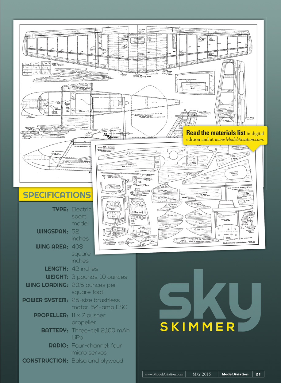
SPECIFICATIONS
- Type: Electric sport model
- Wingspan: 52 inches
- Wing area: 408 square inches
- Length: 42 inches
- Weight: 3 pounds, 10 ounces
- Wing loading: 20.5 ounces per square foot
- Power system: 25-size brushless motor; 54-amp ESC
- Propeller: 11 x 7 pusher propeller
- Battery: Three-cell 2,100 mAh LiPo
- Radio: Four-channel; four micro servos
- Construction: Balsa and plywood
Fuselage
Glue the F4 former and F4 doubler together and clamp. This is where the electric motor will be mounted. After it has dried, glue in F4 to the fuselage sides. I used masking tape and elastics to hold the assembly together. Make sure that the doubler is on the front side of F4.
In the next step, glue the pieces together that will form the nose. Glue part A to part B, and make sure you glue in the top center section of B. Glue in E and F (the bottom sides) before gluing in the top pieces (parts D and C).
Hollow out the center of part A with a chisel for the battery retainer, but don't get glue in it. The battery's position will determine the CG. Sand the nosepiece so that it matches the V-hull at the front of F1. On the top of the nosepiece, draw a dark line using the sanding template provided on the plans and sand to that line to align the windshield.
F1, F2, and F3 are added to the fuselage assembly, again held together with clothespins, clamps, and masking tape. The bottom front fuselage pieces are glued in place and held with clamps while they dry. Be careful not to dent the soft balsa. The upper fuselage rim doubler should also be added and clamped.
Glue on the nosepiece and hold it in place with masking tape until it's dry. Next, remove the fuselage, and sand the nose to match the V shape underneath and the formed windshield piece on top. When the sanding is done, glue the 1/8" plywood water guides to the bottom of the fuselage.
F5 is glued in place along with the upper rear fuselage piece. Some sanding may be required to achieve a perfect fit. Hold this together with elastics, but only put elastics at F5 and at the rear. Put F6 in place, but don't glue it yet.
With the wing joined to the fuselage, use nylon bolts to hold the lower oak wing mounts in place as the glue dries. This step may require some sanding to achieve a perfect fit between the wing and the fuselage.
The 5/16" dowels are put in place through the holes in the fuselage. They are centered in the fuselage, and 5 inches should protrude when the dowels have been glued in place. Next, glue in the sponsons on both sides, ensuring they are angled upward on both sides. Make sure that you glue them in place with the front top as shown on the drawing.
There should be 3 inches between the fuselage and each sponson. Each sponson should be made with the 2" wide balsa, and the outsides should be sheeted with 1/8" balsa. Note that the 3" gap between the fuselage side and the sponson between the wood dowels is filled in with 1/8"-thick, 3" x 6-5/8" balsa pieces. Glue these pieces flush with the top and bottom of the dowels, as shown in the side view on the drawing.
The front windshield is mounted with four nylon #8-32 screws into the two oak mounts, which were drilled and tapped to #8-32 thread. I used four screws to achieve a tight seal to keep water out. The windshield overlaps the nose piece roughly 1/4" all the way around.
The mounting is the same whether you make your own windshield with .015" acrylic sheet or buy the vacuum-formed one that I sell. The vacuum-formed windshield has a slight curve in the profile view of the airplane and the other one will be straight. Both are functional designs.
The upper part of the engine cover is sheeted with 1/16" balsa and the engine cover front piece has been glued in place. The photo does not show it, but mount the motor before sheeting the engine cover. Use epoxy to help secure the four mounting screws. Make sure the motor is oriented so that the wires can come through the hole directly above the upper corner of the rear window.
Sheeting the top is a two-step operation and can be held with tape. Sand the upper edge to a nice radius when the glue is dry.
Final Assembly
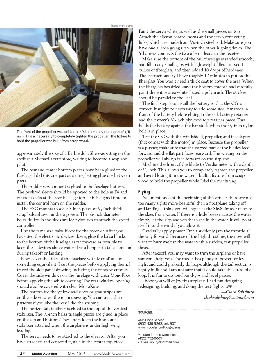
The elevator servo is epoxied to the vertical stabilizer with the servo's front mounting tab cut off. Epoxy the servo to the center of the stabilizer and epoxy along the front of the stabilizer.
I chose to solder the elevator servo wires to the extension wires and use shrink tubing around the connection. Although not required, this makes a cleaner-looking connection.
When you glue in the vertical stabilizer, it may be necessary to trim the stabilizer brace slot so the stabilizer is perfectly vertical. You will want to check this with the wings on. Test-fit the horizontal stabilizer to make sure it sits horizontally. At the rear of the fuselage, glue in scrap balsa pieces to fill in at the F6 location. After the assembly has dried, epoxy in the rudder's pushrod.
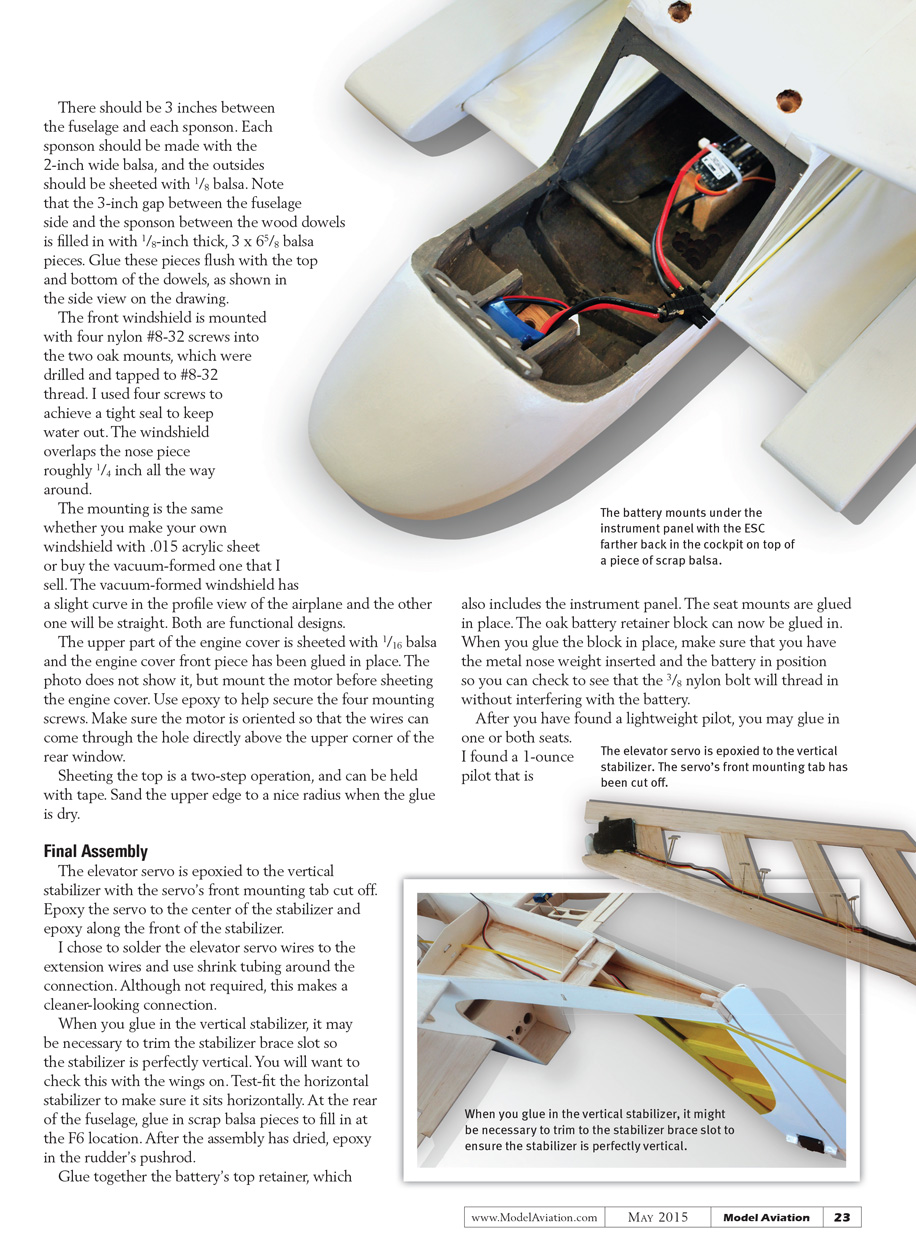
Glue together the battery's top retainer, which also includes the instrument panel. The seat mounts are glued in place. The oak battery retainer block can now be glued in. When you glue the block in place, make sure that you have the metal nose weight inserted and the battery in position so you can check to see that the 3/8" nylon bolt will thread in without interfering with the battery.
After you have found a lightweight pilot, you may glue in one or both seats.
I found a 1-ounce pilot that is approximately the size of a Barbie doll. She was sitting on the shelf at a Michael’s craft store, waiting to become a seaplane pilot.
The rear and center bottom pieces have been glued to the fuselage. I did this one part at a time, letting glue dry between parts.
The rudder servo mount is glued to the fuselage bottom. The pushrod sleeve should be epoxied to the hole in F4 and where it exits at the rear fuselage top. This is a good time to install the control horn on the rudder.
The ESC mounts to a 2" x 3" piece of 1/2" thick scrap balsa shown in the top view. The 1/4" diameter holes drilled in the sides are for nylon ties to attach the speed controller.
Use the same size balsa block for the receiver. After you have tied the electronic devices down, glue the balsa blocks to the bottom of the fuselage as far forward as possible to keep these devices above water if you happen to take some on during takeoff or landing.
Now cover the sides of the fuselage with MonoKote or something equivalent. I cut the pieces before applying them. I traced the side panel drawing, including the window cutouts. Cover the side windows on the fuselage with clear MonoKote before applying the white covering. The rear window opening should also be covered with clear MonoKote.
The pattern for the yellow and silver or gray stripes are on the side view on the main drawing. You can trace these patterns if you like the way I did the striping.
The horizontal stabilizer is glued to the top of the vertical stabilizer. The 1/4" balsa triangle pieces are glued in place on the top and bottom. These help keep the horizontal stabilizer attached when the airplane is under high wing loading.
The servo needs to be attached to the elevator. After you have attached and centered it, glue in the center top piece.
Paint the servo white, as well as the small pieces on top. Attach the aileron control horns and the servo connecting links, which are made from 1/16" steel rod. Make sure you have one aileron going up when the other is going down. The Y harness connects the two aileron leads to the receiver.
Make sure the bottom of the hull/fuselage is sanded smooth, and fill in any small gaps with lightweight filler. I mixed 1 ounce of fiberglass, and then added 10 drops of hardener. The instructions say I have roughly 12 minutes to put on the fiberglass. You won’t need a thick coat to cover the area. When the fiberglass has dried, sand the bottom smooth and carefully paint the entire area white. I used a polybrush. The strokes should be parallel to the keel.
The final step is to install the battery so that the CG is correct. It might be necessary to add some steel bar stock in front of the battery before gluing in the oak battery retainer and the battery’s 1/8" plywood top retainer piece. This holds the battery against the bar stock when the 3/8" nylon bolt is in place.
Test the CG with the windshield, propeller, and its adapter (that comes with the motor) in place. Because the propeller is a pusher, make sure that the curved part of the blades face forward and the flat part faces rearward. The writing on the propeller will always face forward on the airplane.
Machine the front of the blade to 7/16" diameter with a depth of 1/8". This allows you to completely tighten the propeller and avoid losing it in the water. I built a fixture from scrap wood to hold the propeller while I did the machining.
Flying
As I mentioned at the beginning of this article, there are not too many sights more beautiful than a floatplane taking off and landing. I think you will agree as the SkySkimmer takes to the skies from water. If there is a little breeze across the water, simply let the airplane weather vane in the water. It will point itself into the wind if you allow it.
Gradually apply power. Don’t suddenly jam the throttle all the way forward. Because of the high thrustline, the nose will want to bury itself in the water with a sudden, fast propeller thrust.
After takeoff, you may want to trim the airplane or have someone help you. The model has plenty of power for level flight and could probably do loops, although the tail section is lightly built and I am not sure that it could take the stress of a loop. It is fun to do touch-and-gos and level passes.
I hope you will enjoy this airplane. I had fun designing, redesigning, building, and doing the test flights.
—Clark Salisbury [email protected]
SOURCES
- AMA Plans Service (800) 435-9262, ext. 507 www.modelaircraft.org/plans
- Vacuum-formed windshield (435) 752-6665 [email protected]
Transcribed from original scans by AI. Minor OCR errors may remain.

