
NO OCR TEXT NO OCR TEXT youll get very satisfying results care slight breeze model will economy installations large aile- execute outside loops airplane takes rons permit easy consecutive rolls Inside definite directed attitude moderate loops piece cake little winds handling easily Just touch down stick need sustained verted flight itll climb atti tude light breeze Performance well beyond trainer en velope model does spins snaps has quite wide speed range Landings very controlled Given some head wind takeoffs short grass possible low-end power systems Im bi ased think Skyvolt terrific flier As youd expect installing cobalt 15s further augments performance Feed 150 over 200 watts power youve created whole new machine higher power end airplane fast er takes off does touch-and-goes easily executes very impressive square inside loops sure maneu vers within models range have yet try Whatever power combination choose Skyvolt remember everything works much better speed control Dont build model Construction As good Electric structural design emphasizes strength needed light weight everywhere Building tech niques generally familiar straightfor 26 Model Aviation Two different-sized motors accompanied V-block cradles blocks can glued onto motor mount plate inter changed motors have two strips sandpaper attached bottom pre vent slipping Use 1A-in single-sided foam tape cradle edges soft motor set Skyvolt its bare bones showing sticks takes put together keep togesner stage construction no equipment installed should weigh 10 11 ounces Left peek inside cabin Skyvolt showing 10 1 uu-mAh cells position two hidden under windshield receiver double-sticky Veicroed former F3 250-mAh receiver battery pack Veicroed floor under receiver Right Great Planes Gold Fire motor shown strapped place Note fuse visible behind motor speed controller mounted deep down against floor NO OCR TEXT ward basically follow construction guidelines Electrics discussed About Electrics Part Eight April 1984 Model Aviation previously refer enced Spectra article However few assembly procedures Ive devised unique Skyvolt Tail surfaces like start off simple structures Theyre built assem bled quickly feel lot has accomplished very little time Select straight lightweight balsa edges Note balsa edges rud der elevator taper sanded hinge line Follow procedure plan use tape hinges prototype Scotch catalog #190 clear plastic tape 4 4L III__ = I W NG PLANTOP VIEW HID BALSA SOEE WISH RIBS I II FBeALAAr S IIDENTER SECT TEVAR BOTTOM itIi HR TLB BALSA II I SABDOIIW TAR tO x\\\HH I/ AT EDENVIA BALSA SNEEr lop BBALSA WING TIP OVERBOTTOM -NET IN AT A5MAIN SPARALTERNATE TAR N BOTTOMREARFRONT HIS BALSA~fI2IL1I1il IHIA BALSA AlSO HO BALSASWEET I2 CENTER SECTION WEBS WISH BOWEL OSLO SOWN LOCATIONS HR LITE PLOIHBBALSA SHEET FUSELAGE RARE ABATT SUPPORTBABE BASE 2IHABALSO STEET NOSE DOUBLERWING SADDLEROTOOB STARTS H~ 0 BIDET 1_____Al 1 LG MOUNTVIN SLTWOOO LARGER CASEOOSS CS GALS PIRE VG L2 SINALE NERO MOTOR MOUNT V BLOCKS ALL BDONTS SOWN ARE Il/A LWNGI in wide hardware stationery stores See Model Aviation April 1984 prefer employ conventional hinging techniques sand hinged edges accord ingly sure take account hinging method chosen positioning halfcircle cutout rudder clear spruce elevator joiner piece Also sure pencil guide marks stabilizer sembly necessary mounting fin/rudder stab assembly latter fuselage Mark drill /2 holes horn mounting screws rudder elevator shown completed tail structure should weigh about / oz uncovered Fuselage Begin selecting two pieces /16 x 4 x 36-in medium balsa Together should weigh about 15 20 oz Af ter joining sheets double-sticky tape three four places Scotch brand #665 double-stick transparent tape sim ilar product trim edge stacked sides straight using metal straightedge guideline straight-cut balsa side edge IHB BALSA SOEET FRONT I 11 REAR I WING WEBS INS PLOWOSOHB NHA TATCH POORETSCOO HANA GA LSAIHBOIHCI SSWPE os-JELL STOWSCR0 OHE OS N ISHA BALSA C -LA BOTAR ESTOSTELL110 GAL PASELOGE BIDEHaLITEPLC SECTION A-AHOBLITE PLO HIS BALSA SHEET10010 CROSS MAINLAIODISS GEAR becomes fuselage bottom edge Outline fuselage profile balsa prefer using Pilot brand precise rolling ball extrafine pens cut side edge fuselage profile size shape finished pair cut outline typically weighs about 1 oz Mark drill /I6 wing hold-down dowel holes using sharpened brass tube same dimension Separate two side edges remove tape residue lay side sheets accurately over plan side view bottom straight edge bot tom straight edge Using ruler mark sheet sides vertical lines using plan phantoms locate necessary former upright positions shown marking exercise greatly simplifies fu selage construction significantly en hances accuracy alignment during assembly Glue R-in-sq longerons verti cals taking particular care space ac curately former locations use scrap actual former material spacer-guide position gaps formers will placed Add wider 28 Model Aviation Close-up details 0016 x -in brass strip washer plates under 2-56 ma chine screws thread yellow inners Sullivan Golden Rod around mo tor structure air intake well aileron servo linkage mounted wing shows Futaba output wheel S 33 servo pushrods forward off set holes differential aileron throw allows up aileron motion down Clear plastic tape holds servo wire against wing out harms way Full-Size Plans Available See Page 188 S/IS SO RALAG DT~1 L L ] I____ LISRALSA TBUILDING JIG-Il ooROOT SIR Tier AEBTOAL /A BALSA TE ARS TAP SHEET WEDE-]S/A GA S - j GRAINBOTTOMIL ALEROS NDII OLGA DETAILIA ANGELOlA GA HARD GAPIIBALSA SPARS AL TJGEolODE 9 BATTOR OTOj -\\YI7 AOU TORSO EGOS 5181K ODES ALIT JANT AILERONADA PLO BOTTOM SAP UT CAPI/SAG BALSA SELAGE TOP VIEW 5 BALSAOAT OAT PAR NEROG RPLT4Y7\ ASERTDTRATkNN /7 AIRBALSA I/IA SALSA___NADERI/B BIRCA BODEPLOMOAD 7 I/IS BALSA I/ID BALSAMOTOR MOUNT RON HORN BADE A0/52 PLO USA PLOSAND ATE REAR SPAR JOINER ORSOCE / S BALSA-----I--- /MS S/A NOPT BALSA SAGE ISSC ____________ ~OINEOTTIP WING CENTER DETAIL /R BALSAMAIN RARE 2C WING RIB PATTERNS AILEBGN OSROIDI/B BALSA ROBOT 5/IS NS TIP RIB I/A N/B NA BALSACATBGTTHM SINGE OGRE LOADING ROADRIB DETAIL APPUP AGAINST ODE OWE WING TIP PATTERN REAR LA TOGA/IN 5/SOT RID MARIO WIRE TRCSTOCA FINAL NGAPE GA REAR SERGO TO RE I READ SOS/IT IN BSAND TA RAIN STRUT TRODEASELAAECOLLARS LG PATTERNDIG PCOGILGEAD FUSELAGE VIE AGCD PLOWOCO rBOWEL5I/IA S/IATAILGAROLVIEW SSALSA SOGIPSREARING IIDlES I/GRALSA II I II II I II IG __________________________II__ ____________________________________________________________[v32][b32813344200]]AD ES 8I/S SI/S I/IS BALSGA I/ISS 0/IDDALSA 0/AIDSIR/ NADERA/IDS[ I/B SI/ALiDS I/ABALSA ARBALSA SSDEOSADDLE TAPEOlDS I/G RING SADDLEI/B RO I/B NA BALSALIGGADRONS II I/ID I/A BALSAI/G NAPASO SIDE/FIN i RUD G BALSAGERTICAL _______________SDEET /0 GERESUPPORTSICR ASEEP_______ IIHALSA S/BPSBALSA S/BPSSOEDO lI/AS 0/BADS fliS/ISSECT B-BI/BS A/GA5/0/BALSA HE-A BALSAPSCRAP BALSAII I/GSA BALSA lII/GDLOIIBALSAI] I -C IIIOI- fL~IITBAR /RI/S BALSA U-I I4J/OORNDTDARI/I0/BAL5ASAED UR IIRS I/A IIGDBALSA FUSELAGE VIEW OPECIFICATIONG / ELEVATOR TRFSTOOR / II SCMS SUB BALSA BELOW STA ILIZER_ 3/A GALSA --ELDA BORN STEET I IBOTTOMI 0/ID BALSAETAPE TODETLEI \56BSAI BALSA S/A DUCT AIDE S/ID NA CRS S/IS 5 AG 0'ASAS0/ MODEL AVIATION S KY VOLT DESIGNED BY BOB KOPSKI TRACING BY 30E DEMARCO IALL RIBNTS RESERVED A-in-thick strips pieces undrilled /8-in wing saddle doublers /8-in Lite Ply bottom nose doublers Go over entire structure sanding block get rid bumps irregularities Drill through wing saddle doublers dowel locations using holes side sheet guides Add A-in-sq hard balsa pieces landing gear area /8 x %-in strips hatch area front triangle fill stock light balsa in side battery guides shown Mark cut out pushrod exits Block sand edges both sides match Cut out formers servo tray motor mount pieces landing gear plate materials indicated servos other S-33s shown youll need modify servo mounting plate accord ingly Only microservos recommended model Note former F4 has some added balsa strip material front back top wing saddle V A6 x A-in strip back depressed /16 below V provide rest fuselage top sheeting just aft former location Begin boxing up fuselage method described several possible approaches Position glue form ers side using small triangle -Hi-TROD Left Details tail wheel steering linkage pushrod goes directly rudder via short Golden Rod psuedo turnbuckle wheel collar pushrod end tees off linkage 4-40 Stud bolt ball link Another wheel collar silver soldered tail wheel strut has similar stud/ball link arrangement During final assembly just connect two ball links shown Right finished stabilizer/elevator structure Note line marking guide fin attachment after covering Similar marks bottom will assist attach ment tail assembly fuselage Make certain remove covering material may have adhered between line marks January 1990 29 Left The completed fin rudder framework triangle stock side bottom yet added Above Initial steps constructing fuselage two side pieces bottom-to-bottom show location lines drawn place lines make life lot easier positioning formers accurate assembly structural alignment sure orthogonality Bring remaining side substructure position against formers clamp rubberband ap propriate everything seems aligned apply CyA cyanoacrylate appropri ate places Install /8 x 3A-in battery support strips between formers F2 F3 strips serve dual function First per mit air scooped under motor mount ing plate pass through lower cutout former F2 flow up among battery cells pass over top former F3 exit rear opening fuselage Second hold battery pack upright fuselage maintain high center-ofgravity vertical location improves execution roll maneuver battery support strips place block snad fuselage bottom until flat install A6 landing gear plate gluing well attach bottom sheeting former F2 beyond F4 shown Position fuselage over plan top view pin securely Use some scrap /16-thick pieces block up rear ends fuselage sides away building surface Draw sides together rear following top view guideline Make crosspieces favorite method cut single strip /16 x /2-in balsa length crosspiece location cut half lengthwise make two A-in-wide crosspieces equal length Install crosspieces top bottom locations shown Remember raise bottom ones /16 Use small triangle clamps necessary assure fuselage squareness integrity assembly stall rearmost top ply tail wheel strut bearing plate shown Add /16 top sheet trailing edge stock stabilizer leading edge Add top sheet just aft F4 depress ing F4 form juxtaposed /16 x A-in strip previously placed former V shape blending flat shape aft point Add top edge /16 x A-in longeron caps A6 x /6 crosspiece caps Lift fuselage structure work bench turn over install bottom tail wheel strut bearing plate Add bot tom longeron crosspiece caps Notice balsa intersections form multisur faced jointsan indication exceptionally strong light construction Make rear hatch rest plate adding /8 x /2-in balsa cross strip between fuselage sides rear hatch open ing against F2 front Install balsa windshield using light easy-to-form /16 A-grain sheet Cut small notches /16 wide /8 deep fuselage sides very bottom windshield will inserted Install /8 x 5A6 fuselage crosspiece top previously installed hatch rest against windshield front edge Trim %2 front edge right fuselage side sets up nose correspond two degrees right 30 Model Aviation finished fuselage sides formers ready assembly fuselage front bottom should also shaped according plan protile before actual assembly undertaken ueiaiis rearward side F2 showing AG x 4-in strip following gentle V former top strip set Ae below former top strip front-facing side 1-in material provides sad dle area wing trailing edge rest Left A look upside-down fuselage during installation landing gear mounting plate servo tray has already installed Right fuselage sides have pulled together nose glued motor mount thin bead CyA top bottom thrust indicated Make up appropriate V block fit particular motor shown plan Loosely attach motor mount plate proper amount right thrust spot gluing using doublesticky tape Minimal attachment allows easy removal replacement should decide change power systems later date motor clamps ensure secure loca tion motor-holding V-blocks Pull fuselage front sides together against motor mounting plate rub berbands clamps latter should rest squarely top edges A-in Lite Ply bottom side doublers Check out thing alignment glue motor plate place Install top / x -in balsa front crosspiece /8 x -in topmost crosspiece Block sand very front fu selage taking care get edges flat preserving side thrust dimension Install A-in-thick cross-laminated sheet balsa nose former Fl Complete bottom fuselage sheeting front landing gear plate Note sheeting continuous point slightly yond rear edge motor mount plate Partial narrow sheeting continues along two lower fuselage edges well ward area however later sanded blend fuselage front simple hatch used Skyvolt has proven easily made structure functions very well field Make hatch cross-grained lightweight A-in balsa shown cutting trimming fit neatly front top fuselage hatch re cess its just right size shape bend upside-down over scrap A-in strip shown photos Attach two /32 ply strips shown CyA making sure extend about /16 past front edge balsa hatch Like projecting toes strips tuck under neath uppermost forward fuselage A-in balsa plate Note strips also cut back rear edge hatch clear rear hatch rest plate rear hatch held down hatch recess nylon landing gear strap functions catch bowed hatch pops up catch moved clear Give completed fuselage thorough sanding Take time round cor ner edges nose former etc gener ously possible Youll laying foun dation very eye-appealing model covered Assemble landing gear trial fit place ply mounting plate Use %-in No 2 sheet metal screws /16 pilot holes secure nylon landing gear straps certain drill holes /l6 inJanuary 1990 31 Left Close-up view showing details fuselage side subassem blies nose back former F2 Above Fuselage begins take shape way assemble fuselage install form ers side first sure proper position square before installing other side Triangle ensures vertical alignment Details ot tne aimost-tinisnea tuseiage nose section ready nose block installation close-up view fuselage sticks Assembly actually difficult sounds text Multisurtaced loints very strong Theres no need sheet top bottom landing gear made up %-in-dia music wire Locate straps same di mensional relationship building block fuselage front wire should vertical Bring up rear strut bend nec essary bind copper wire solder joints assembly very strong Trial fitting landing gear Use /8-in gear straps front strut %2-in rear struts Use #2 x 3/8-in sheet metal screws set 3As inside fuselage sur face Epoxy fiberglass matting over gear mounting plate Cut out lightening hole epoxy set before final sembly gear visible structure side fuselage battery support rails ward outside fuselage dimensions meet center 4-in hard balsa strips underneath ply plate Bend install tail strut centered /16 bearing holes top bottom ply plates shown rib-to-trailing-edge assembly Use 3A6-in stock under ribs piece V2-in-sq steel key stock weight down structure its assembled pictured TE jigs shown plans help supporting trailing edge its CyAd ribs Details tail wheel strut assembly Wheel collars top bottom keep strut place top collar setscrew can made accessible either through rear opening through notch may cut fuselage side under stabilizer 32 Model Aviation Left Close-up windshield area hatch cover recess vis ible Follow text photo fashion yours same way Above simple functional hatch cover Pin cross-grained 1/i balsa sheet over 4-in strip Pin down ends sheet Add 1A2 x %-in-wide ply strips CyA position Note exten sions strips front cutbacks back hatch photo shows springy hatch cover tensioned place plastic landing gear hold downs yet installed makes simple positive hatch installation look air scoop structure formed bottom motor mounting plate bottom sheeting faired curved fu selage sides nose block fashioned laminating two pieces 1/8-in balsa cross grain sanding final shape Trial mount servos make rud der elevator pushrods Remove trialfitted hardware put drop thin CyA screw holes harden threads Fi nal sand fuselage set aside covering point structure should weigh very nearly 3/2 OZ ailerons incorporate some unusual con struction techniques deserve some de tailing like build before conWing center short rib notches servo rails Use actual servo notch guide Locate servo deep wing allow motor battery clearance wing place structing wings Theyre fun assem ble Since ailerons relatively large area theyd heavy built out solid chunks wood conventional way gained needed lightness making hollow ailerons designed very strong twist resistant well ailerons require less two full sheets %6 x 3 x 36-in balsa prefer Cgrain sheets Alternatively can use 4in-wide stock rate choose light est wood can find Study photos well Begin cutting Lite Ply template l%2 wide about 6 long Cut end balsa sheets 450 angle proceed slice off bottom trailing edge sanding operation described text 14w x 3A6-in tem porary balsa strip double-sticky-taped over bottom rear spar sanding block has tape cover rides strip during sanding simple step raises sanding block high enough clear ribs fairing trailing edge close-up shot 1Ae X /i6-ifl strip initial step building rear wing center structure Its location crit ical position accurately possible bottom view completed wing center section Note aileron servo cutout installed aileron torque rods pieces using template stop block pinned work surface shown Cut off necessary number pieces laid end end total length will enough make surface bottom both ailerons January 1990 33 main spar webs being installed left wing /2-in-sq steel key stock bar weights down structure against temporary 3A6-in balsa strips under ribs negate warping vetatis wing structure during assembly major part internal right wing struc ture completed photo Note tapered spruce rear spar doubler place Assembly rear center structure underway piece %-in tubing placed temporarily establish location x 3A-in strip behind tubing rests previously installed A6 x %6-in strip outside trailing edge strip Since top surfaces must little wider bottoms theyre made lit tle differently Add /16 wood wire spacer between template stop block cutting second sheet results %2-wide sheets will used aileron top surfaces Pin metal straightedge place po sition /8 x -in balsa aileron trailing edge TE cap against straightedge pin strip place four inches careful note grain direction aileron Begin placing narrower bottom balsa sheets ones cut first against trailing edge stock pictured Sand needed good fit around Using piece wood hold small sheets tightly down against building sur face time run thin CyA along sheet/TE-strip joint Dont glue mating edges sheets together generally makes CyA mess underneath Instead use short lengths /16 x 4-in stock thick CyA shown connect sheets other sure joiners located off fore/aft cen ter shown wont interfere similar pieces installed under neath top sheets later front sheet leading edges ragged along aileron length remove subas sembly board carefully sand smooth long sanding block Af Continued page 135 Left aileron torque rods installed %-in-OD aluminum bearings Position tubes carefully temporarily tape ailerons place correct alignment Right wings being joined together epoxy dihedral joint Use rubberbands epoxy sets Left plywood wing dihedral joiner being epoxied place Clamp firmly place until epoxy sets Right dihedral bracing servo box structure detailed text also similar %2-in plywood dihedral brace inside surface rear spar template accurately slicing aileron sheeting 45 Butt sheeting against block let template guide knife Top sheeting wider bottom See text Root-end shot completed ailerons slip tubes place Note 1/a4-in plywood reinforcements top bottom Left Attaching aileron leading edge / x -in hardwood strip wood blocks hold strip vertical CyA applied Move along entire length aileron manner being careful glue blocks Right Top aileron sheeting being installed Note short e x 3A6-in balsa toe sheet being installed sheeting goes against trailing edge top leading edge Note top bottom sheeting cross-grained Use thick CyA balsa toes leading edge thin CyA sheeting attaches trailing edge 34 Model Aviation SR Battery Packs Make Clean Sweep 89 KRC Electric Fly! Saturday Sunday September 16 17 10th annual KRC Electric Fly held Quakertown PA year two different types endurance events held Saturday Sunday Although weather miserable Saturday up last down event held 12 contestants participated four top finishers using SR packs First place won using SR 1250 Series Magnum pack second place won using SR 1250 Series Magnum pack third place won using SR 1800 Series Magnum pack fourth place won using SR 900 Series Max pack Sunday weather much better different type endurance event held Instead simply longest possible flight contestant made series 4 minute flights 2 minute period between flights retrieve planes allowed recharge change battery packs between flights contestant logged highest number 4 minute flights plus number seconds last flight won objective minimize affect thermals outcome event again SR Battery packs made clean sweep event First place won using SR 1250 Series Magnum pack second place won using SR 1000 Series Max pack third place won using SR 1250 Series Magnum pack As can see comes Electric Power battery packs SR Packs cant beat Two years ago SR recognized need series cells designed exclusively electric flier new series would have give electric fliers longest possible motor runs lowest possible weight new SR Magnum Series cells outgrowth research development Magnum Series cells pack 40% 50% capacity cell increasing its size weight Magnum cells primarily designed Sport applications maximum current load 12 15 amps intermittent applications SRs EP Max Pack Cells other hand designed lowest possible internal impedance could handle extremely high current loads continuous discharge rates 15 30 amps SR Max Pack cells best choice rather Magnum cells addition Electric Flight battery packs SR now Stop source Electric Flight supplies SR now stocks motors props chargers wire connectors switches just about anything else might need Electric Flight addition everyone SR will too happy answer questions help solve problems might have place order ask question can reach us calling Hotline 516-286-0079 between 9am 5pm Monday through Friday youd like us send literature send self addressed business size envelope 50 cents postage SR Batteries Inc Box 287 Bellport NY 11713 -ADVERTISEMENTSafety/Preston Continued page 22 agreed way thinking Back May 1980 Safety column published list flying field rules compiled rules differ ent clubs list contained 43 different rules intention clubs should select believed applied operations list did ad dress pets Rule #39 Pets shall con fined spectator area did specifically address kids However two rules applying adults seem equally appropriate kids Rule #11 Spectators welcome must remain designated area lieve should also apply young chil dren unless escorted parent club member gnated area spectators does include pit area flight line Rule #21 Pilots must stand marked pilots box Only pilots instruc tors spottersare permitted stand pilots box dont believe children toddler age likely qualified pi lots instructors spotters other words dont believe toddlers should permitted flight line So now have opinion right ful place children flying field However please dont misunderstand am very much favor hobby being family affair possible Bring kids flying field means own protection please dont let roam around unsupervised As column points out month accidents hap pen Lets have victims children encourage anyone wishing express different viewpoint concerning issue write Meanwhile lets have safe month Skyvolt/Kopski Continued page 34 ter repinning place add hard /16 x -in leading edge strip top ai leron bottom sheets shown Making sure strip perpendicular surface easily done small blocks pictured spread thin CyA along joint Take care glue blocks process Lightly run felt-tip marking pen over top edge leading edge strip color Using small sanding block tape covering corner edge carefi1ly sand away darkened top edge leading edge strip As maneuver tape-covered corner block bottom sheet-TE joint color disappears youll know leading edge top edge tapered proper angle Its important oversand very front edge strip must remain /4 high Y6 building sur face Fill root end of aileron ta Continued page 138 IA ES MILLS METALS BOOKS PRECISION INSTRUMENTS COMPLETE CATALOG $2 00 1 OUls 0, 4VPDIU FULl Cl S 2100 M So Road Spo oqt old Oh o 45505 mpa 322 8562 January 1990 135 THE WIREMASTER o bender/coder extra large handle bends 118-114 coils 5/ 32-3116 music wire Wire creep eliminated ANTI-KREEP WIRE LOCIV free catalog has hundreds new items free miCro bender offer JCM COMPANY 114 Washington Ter. Waukegan IL 60085 IS* WE BUILD YOUR HELl TEST YOUR HELl YOUR HELl I1- Lehighton Pa 18235 WRITE OR CALL FOR INFORMATION Skyvolt/Kopski Continued page 135 pered -in balsa Begin laying top sheets place applying CyA go along Make absolutely certain top sheets run cross-grained lower sheets sure add /16 x -in joiner top sheet piece installed best done first attaching about half length joiner top sheet piece youre about install positioning assem bly place against previously installed unit adhering thick CyA sounds difficult isnt Studying photo should give confidence Remove aileron structures bench square up ends cap outer tips A-in sheet Rough carve trailing edge strips sand blend aileron taper Sand aileron its entirety removing irregularities leading edge top bottom sur faces caveat Remember lightI II II II Washable ed Cap Sunglasses nip up/Down Adjust In/Out Snap On/Off Imprints Available Ultra Violet Protected Please send _____________ caps Ive enclosed I @ $795 plus $2 shipping handling I Lets Colors 0 Amber 0 Smoke blue Cap Colors LI Black LI White LI Yellow I EiJ Green LI Navy blue LI Royal blue LIMaroon LIGrey El Red LI Please send information about imprinting PLEASE PRINTI II II II II I_____________ ___I II Name Address city StateZip RETURN WITH CHECK OR MONEY ORDER ONLY TO PIN-NIK SALES PO Box 647 Ravenna OH 44266 L weight wood sands away too easily Take care oversand flat surfaces learned hard way goal no re tain basic aileron thickness Notch root ends shown accu rately CyA A-in length %2-ID alu minum tubing place Add root top bottom pieces 4 ply Make sure inside tubing remains free adhe sive aileron horn slip tubes essential smooth operation ailerons wing itself requires less unusual build ing techniques should clear plan pays begin accurately marking rib locations leading trailing edge strips using small square triangle ribs cut out begin assembly locating main bottom spruce spar over plan As aileron trailing edge piece use metal straightedge Position spare piece 3/16-sq balsa strip temporary support under ribs about 3/4 forward trailing edge lo cation adjust necessary Place three center root ribs position spar pin posi tion After checking theyre accurately positioned apply CyA rib/spar joints Bring leading edge piece po sition against ribs using marks ac curately locate ribs hand hold rib place CyA joints trailing edge should firm straight strip /e x /16 balsa like cut own strips sheet stock until come out straight Bring trailing edge piece up against ribs using balsa trail ing edge jigs shown support rib top edges should perfectly flush top trailing edge strip CyA rib trail ing edge joints locations marked TE center section ribs course cut thinner accommodate top bottom center section sheeting keep mind setting place Take spe cial care setting A-in root ribs using dihedral angle guide given plan Cut out guide glue heavier card stock trim shape before using Get ting rib angle right will save lot grief later Install false ribs Slip place tween leading edge main bottom spar line up CyA place Install main spar webs add top main spruce spar Install rear top balsa spar tapered spruce spar dou bler Remove wing panel board flip over Install rear spar webs bottom rear spar tapered spruce spar doubler Complete top bottom center section sheeting forward main spar rearward rear spar between spars Add A-in tip plates both panels assembled stage sand root ends large flat sanding block before trial fitting dihedral joint Continue sand carefully achieve good fit correct dihedral Carefully sand leading edge shape noting very little material removed top somewhat bottom ribs make contact Also note very leading point leading edge very slightly rounded dont make 138 Model Aviation 4b4 415 342 5581 GOLDEN GATE HOBBIES PO BOX 282005 SAN FRANCISCO CA 94128 M/C OR COD CATALOG $ 200 OR FREE WITH ORDERS HATORI BLUEPRINT SHOWS ALL EXHAUST ITEMS FULL SIZE 2FT X 4FT $ 5 HA TORI RA DIGICON M-MSK WE NEED DEALERS WHEN YOU FORGET\OUR UNITS REMEMBER RC System NICd Batteries chargers need packagel Cycler-Chargec *23996 Fits 48V Rx 96V Tx packsPlus $6 S&H Others available write call TrIckIer*34961Regular Model . *4695 ForPlus $3 S&Hsge si%iFor field kit sinaiPlus $3 S&H Mue electric boat batteriesSpecify 612 24V Heavy Duty Model 6 sport winch large boat andPlus $4 S&H electric power charging batteriesSpecify 6 2V CaRa Productssselomasen PO Box 221 605-987-5924DeaiernqaneswwiedCanton SD 57013 cO& 4 Rrh Stuff First Step Model Airplau Simple Simon Airplane Co PO Box 18 East Lonameadow MA 01028 4135923615 BALSA WOOD STiCKS 1/16-INCH3648 1/1601/1606 1/163/3207 1/1601/808 1/1603/1609 1/1601/410 1/163/813 1/1601/216 1/1603/421 TAIBI 1/8-INCH3648 3/8-INCH3648 1/601/808113/803/8 1/803/1611153/8o1/2 1/80 1/413173/8 3/4 1/80 3/81621 _____________________ 1/801/21724 1/8 0 3/42533 3/18-INCH3648 11 133/1603/181317 153/160 1/41418 173/16x3/81621 203/1601/21826 283/16 0 3/42836 3/32-INCH3648 1/4-INCH3648 3/323/3209111/40 1/41621 3/32 o1/809131/4 r3/81820 3/323/1610151/4 rl/22129 3/3201/413161/403/43142 3/3203/81419 3/3201/216218/16-INCH3648 3/32 0 3/42431 5/1605/162027 Doable Balsa Wood5/16 0 3/82230 Pnces Spruce5/16 0 1/22736 Basswood Sticks 5/16 0 3/43952 2737 3041 4480 1/2-INCH3648 1/20 1/23749 1/203/45270 TRIANGULAR CUT BALSA 1/401/403624 3/803/803628 1/2o1/2o3637 3/403/403047 10103661 BALSA PLANKS 3/403036178 102036194 1o3o36230 104030303 2o2o36230 203030329 204036464 3o3o36490 3o4o36680 BALSA SHEETS 1-INCH3646 11160 12738 3/32013040 1/8 0 13344 3/160 13748 1/4o 14107 3/8 0 15372 1/2 0 16589 2-INCH3648 1/32023040 I/16o23648 3/32 0 24154 1/8u24680 3/16o25472 1/4028384 3/80277103 1/202113150 3-INCH3648 1/32034053 1/16034358 3/32 0 35270 1/8036080 3/16 0 37295 1/40384112 5/1603103134 3/803120160 1/203150200 4-INCH3648 1/32048587 1/160473101 3/32 0482109 1/80495128 3/1604114151 1/404131183 3/804182271 1/2 04219325 BIRCH PLYWOOD 1/84012012182 1/84012024384 1/640 12049728 1/640480492912 1/320601260 1/32012012119 1/320 12024237 1/320 12048473 1/160601259 1/180120 12117 1/160 12024234 1/160 12049466 3/320801291 3/320 12012181 3/32 0 12 0 24362 3/32012049723 1/8060 12100 1/8012012199 1/80 12024397 1/8o12o49784 3/180801274 3/160120 12148 3/160 12024293 3/180 12048985 1/40601274 1/4o12o12144 1/4 0 12024293 1/4012048585 3/8o12o12180 3/8012024360 3/8012048720 1/2 0 12o 12202 1/2 0 12024405 1/2012048808 LITE PLYWOOD 1/8o12a1256 1/80 12024112 1/8012048224 TAPERED TRAILING EDGE3646 1/80 1/22230 3/18 0 3/42940 1/4 0 14255 5/1601144481 3/801145272 * OPEN TO THE PUBLIC * Superior Aircraft Materials 1 2020-G Centralla iian Gardens California 90716 865-3220 Handling Charge -$500 $300 COD mum Order $2000 FOB Factory accept Personal checks COD fornia Residents add 6% Sales Tax blunt Pay particular attention photo detail ing sanding lower edge trail ing edge strip accomplished tem porarily attaching piece /16 x /o6 balsa top bottom rear spar using double-sticky tape Put piece tape edge sanding block run block tape against added strip untaped sanding part cuts taper trailing edge strip shown produces excellent blending rib shape lower TE finished rearmost surface trailing edge strip should % wide hair Build rear center sections pan els Begin marking rear trailing edge strip root guidelines /16 bottom / top Glue /16 x 3/I6 balsa strips locations shown plan Place panel bottom-down work bench Block up near leading edge scrap stock bottom air foil section tangent building surface trailing edge Note grain direc tion glue /16 bottom center sec tion trailing edge sheeting beneath /I6 x /I6 strip Add % x A-in cap rear edge sheet Add two A-in triangular riblike pieces root outer edge loca tions Add soft x %-in balsa fill tween ribs /8 trailing edge pictured aluminum aileron horn bearing will rest gap upon upper edge /I6 TE strip Run sanding block over assembly blend soft strip just added Sand trailing edge cap strip shape Sand wing root once contour added trailing edge structure proper dihe dral angle Final sand wing panels satis faction make dihedral joint actual dihedral measured tip un der main spar should plus mi nus /8 prefer make dihedral joints Hobby Poxy Formula mix up batch lightly coat root end grains panel planking spar ends let soak 20 30 minutes mix up fresh batch make joint clamping otherwise holding panels together few hours joint accomplished cut away four centermost ribs sand back surface front spars front sur face rear spars smooth Cut ep oxy 3/ ply dihedral joiners shown Note joiners should first marked locations two short ribs form sidewalls wing servo box Note also joiners fit /16 inside top bottom spar outer sur faces center planking rests Cut two short ribs shape Using servo guide mark notch ribs servo rails Its very important lo cate servo close upper surface wing order maintain maximum clearance wing fuselage Install ribs servo rails between spar joiners marked Add center section sheeting top bottom between main rear spar locations keeping servo box clear Shape aileron horns Goldberg Y32 horns using %2-ID aluminum tubing shown bearings Drill carve clearance holes wing near trailing edge allow passage horn Tempo rarily fit horn/bearing assembly posi tion carefully checking alignment slip ping ailerons place verifying loca Continued page 143 h LsAA ___3rdk CeatrelLine P1gct*t Modelers eng Mode e Finishing FriendTools88 Control Horns 6 HeavyiutnBeltoranksHandles AdIustahIeLeadoutOuideutlassic kits Custom Motor Moanto much much morel Aluminum Inserts ANSAEPASSLD QUALITYGUA8ANOEEOSATISF8COIAM Send name address SlAG receive Nour new eopaednd catalog will get 52 00 ott first Grdnr fl9 CraftaTian Models Inc 1311 L 1616 8Mn81w60 hro 44074 dealer inqniries incited January 1990 139 Paper Flying Scale Model Airplane $7 MLL PARTS PRE-CUT & PRE-PAINTED BUILD g FLY IN TWO HOURS PAPER AIRPLANES 433 NIHOA STREET KAHULUI HI 96732 USA CATALOG $750 Contains 1000 er airplanes ostage stamp size 6 foot wing span Gliders rubber powered Die-cut youcut Largest known source paper airplanes world Cost catalog deducted 1st ordr over $2500 ASTOUNDING CatizLoQ avid AIR papet uzUtpian#z aboue $1050 peuA $250 pohtage ULTIMATE 10 DASH 300 BIPLANE Fiberglass fuselage balsa-sheeted foam wings Quarter-scale 13 Ibs 62 Span Level 1u MIL-F-8785C ST 3000 Flying Q Power alities Sold reservation $75 refundable deposit includes data package $15 separately Comprehensive kit $554 finished unpainted aircraft $1550 powerplant radio gear included Production limited eight hand-crafted individually numbered aircraft per month Satisfaction guaranteed money back Phone FAX 801-753-1971 VISA MC check no COD DAEDALUS RESEARCH INCORPORATED An award-winning design laboratory e 1983 creating advanced concepts military civilian Unmanned Aerial Vehicles tion freedom movement etc After re moving assembly CyA tube bearings place Make sure horn wires very free-moving before continuing Cut glue position single-piece /64 ply top wing center cover sheet shown being very careful get glue around horns bearings mess up youre big trouble use thick CyA operation spreading carefully Notice nicely ply sheet conforms dihedral shape wing woodwork including ailerons horns should weigh about 6 oz Covering Final sand completed struc ture satisfaction before covering prototype used MonoKote film covering choosing will work Before covering fuselage apply iron-on cloth reinforcement landing gear mount area Use paper towel Xween iron cloth keep stickiness cloth off iron Poke holes cloth screw hole loca tions cover fuselage what ever film desire Cover fin rudder stabilizer el evator wing ailerons separately course dont cover glue joints yet made Hinge moving surfaces Since aile rons relatively large its important check out warps before hing ing Using double-sticky tape attach two short pieces balsa stick top surface root tip sight ailerons signs twist Correct warps detect Tape hinges best ailerons conventional hinges may used tail pieces noted earlier sure set 1/16 gap hair less before applying tape Final assembly Glue fin stab glue entire tail assembly fu selage Mount landing gear wheels tail wheel assembly landing gear hardware total weighed 22/s oz stall radio connect rods link ages check out installation smooth nonbinding operation correct throws etc sure make small notch fuselage side rudder horn throw clearance Install wing servo linkages Note off-center servo wheel pushrod hole lo cations achieve aileron differential Also note short pieces 1 2 yellow ner Golden Rod material used quasi turnbuckles easily adjust rod lengths everything installed except power system components Skyvolt should weigh 22 24 oz Install power system components Note popular seven-cell model car batteries will fitanother difference tween Skyvolt trainer designs pack can adapted pictured re assembling fit battery supports between inside fuselage battery guide strips Note side guide strips finished / x A-in wing sad dle tape hold battery pack snugly Leftover battery compartment space should filled custom-fitted foam blocks further snug pack also ensure incoming air forced among about cells battery pack fit must tight enough hold battery place Skyvolt inverted planes flying inverted pass low enough cut groove ground fin dont want battery banging against aileron servo theres question about snugness install some hooks 71 span 58 length 920 sq wing area 38 o per sq ft wing loading Weight 14 16 lbs Power 80 108- two cycle 12- four cycle F4U CORSAIR Finished fuselage 062 Aircraft Quality ABS over crutch & ply bulkheads bulkheads including % ply firewall installed wing design formed ABS Gull covering makes wing snap build Built up tail feathers Complete hardware decals Complete instruction booklet plans AV/ order call write 7p GM Plastics Inc 7252 Industrial Park Blvd / Mentor Ohio 44060 /216 953-1188 January 1990 143 Electric Flight off Controller Perfect 05 Motors 510 cells month Has Broke Lightweight 12 Adjustable switching money back Soideriess terminal ror easy hookupgooroflteo ON/OFF ContraIl er$2495 Power save weight 20 5ize 22x13x63 v high efficIency 006' toss Add SlOlfoeshipping Colifoesis cesidents odd 65% 1163 Tso Send check mosey order Cowessni11HIgh Sky Fotaha esnierotor o 3929 Kansas St #9 San DiegoCA 92104 COMPETITION ACCESSORIES & CUSTOMIZED K&B ENGINES RACING WHEELS KLOTZ OIL CARBON FIBER SOLID LINES ALL KINDS OF FUEL TUBING FOUR BRANDS OFGLOWPLUGS HARD-TO-FIND HARDWARE OLD TIMER SUPPLIES COILS CONDENSERS NGK & STIlT SPARK PLUGS SILK 12 COLORS QUALITY DOPE BRUSHES 5& 7LOOP 1/4RUBBER BANDS TRANSISTOR IGNITION SYSTEMS RESISTOR HIGH TENSION LEADS 1/2A TEXACO PLA YBOYSR KIT 1/2A TEXACO ENGINES & PARTS KSB & IGNITION TIMERS RUBBER POWER KITS PROPS TISSUE AND OTHER SUPPLIES CYANOACRYLA TES & EPOXIES WHAT bo YOU CALL THE BEST SHETING Tigers MATERIAL FOR FOAM WING CORESkins WWIsoOetlanmeara coot0COy ttsaetaothOocoOt taOttaood tOt scooleIcomoog orogttataoaaflaao OOcsot t05500a aO ateinSet Ooo OS O.t athSaoTlgekl area ma Iroartto aaoooSttmOCoatrasetotoeccoresoaoatoeocsatflareeoeaOne 05Th, CHECK THESE FEATURESComes n following Colors Srtoertrstrengtr tows 5fl5 ratoWaco Ret Superror 0000 oaseElitt teamPolar Wote 051 per sO inn tetrtperastre Stahl 50losiptina SI.e Smooth flingS tttt hoistSIn hellew Superinor res stance tinem Otel Stoerorresstenoeoeweester Easy applo ttw low cost l/A4aS3eOSsee 5tonin 000th V0vo0rototO roOt 0 Phonea 3093423009 WV6 MF6 OttO OSOte 0tCc oreO terltoratureda toot ttt5305cinctttltottttsoosto Ott SO 40 coccinos ltr SENT $400 FOR CATALOGI inotins Resindeots eoe 5 1 /2C0 sa sac WING Mfg 306 E SimmoRs Galesburg IL 61401 upper surfaces side guides loop some rubberbands over pack keep place Install power system wiring using preferred method course will determined choice power components speed control etc should plenty space behind motor fit interconnection goodies As point interest install speed control heat sink airstream enter ing under motor mount plate However take care overly block air passage through F2 Clamp motor place using yel low inners small Sullivan Golden Rods C-clamps Cut rods short about in on side prevent touch ing motor mount plate drawn tight 2-56 screws passed through motor mount plate rod ends Installing draw screws made easier first running 2-56 tap yellow rod material Also screw heads should rest 0016 x -in brass strip washers bottom motor mount plate shown See Model Aviation July August 1987 de tail technique Flying preflight check Rubberband wing place carefully check adequate clearance between motor bat tery pack aileron servo linkage really important however taller l200-mAh cells Correct inadequate clearance find Suggestions include trimming bottom battery rails about using -in wing saddle tape instead /16 size shown using smaller servo remount ing servo deeper wing balance check Depending motor chosen model may tend nose-heavy Balance model main sparnot front behind motor battery less t2 cells can moved fore aft help accomplish bal ancing needed Just sure fill up leftover space foam blocks re check clearance discussed above receiver battery may also relo cated behind servos /16 fuselage bottom sheeting installed rea son use double-sticky Velcro Radio Shack purpose sure coat balsa glue such Ambroid first allow dry sticky part Velcro sticks Lastly else fails re luctant am suggest small amount weight may added very rear fuselage negate stubborn nose-heaviness powered Gold Fire motor seven l2-mAh cells Skyvolt weighs 46 oz all-up Equipped fer rite 15 12 900-mAh cells model weighs 51 oz Most Skyvolts should fall somewhere between limits first flights suggest hand launch just check everything out espe cially recommended lower end power systems Gain some altitude before Statement Ownership Management Circulation Required 39 usc 3685 lA Title Publication Mode/Aviation lB Publication No 087930 2 Date Filing September 28 1989 3 Frequency issue Monthly A No issues published annually 12 B Annual subscription price $1800 4 Complete Mailing Address Known Office Pub lication tstreet city county state ZIP code printers 1810 Samuel Morse Dr Reston VA 22090 5 Complete mailing address headquarters general business offices publisher printer 1810 Samuel Morse Dr Reston VA 22090 6 Full names complete mailing address pub lisher editor managing editor item must left blank Publisher Carl R Wheeley 1810 Samuel Morse Dr Reston VA 22090 Editor Carl R Wheeley 1810 Samuel Morse Dr Reston VA 22090 Managing editor None 7 Owner Academy Model Aeronautics Inc 1810 Samuel Morse Dr Reston VA 22090 8 Known bondholders mortgageea other se curity holders owning holding 1 percent total amount bonds mortgages other securities None 9 For completion nonprofit organizations autho rized mail special rates DMM Section 42312 purpose function nonprofit status organization exempt status Fed eral income tax purposes 1 Has changed during preceding 12 months Extent Nature Circulation 10 Actual AverageNo copNo cop- ies single isissue dur- sue pub ing pre- lished ceding 12 nearest months filing date ATotal No Copies Net Press Run116313129500 BPaid and/or Requested Circulation 1Sales through deal ers carriers street vendors counter sales33553513 2Mail Subscription109588123010 CTotal Paid and/or Re quested Circulation Sum lOBi 1082112943126523 DFree Distribution Mail Carrier Other Means Samples Com plimentary Other Free Copies24542380 ETotal Distribution Sum C D115397128903 FCopies Distributed 1Office use left over unaccounted spoiled after print ing660590 2Returns News Agents2567 G Total Sum E Fl 2should equal net press run shown A116313129500 11 certify statements made cor rect complete Carl R Wheeley Editor Publisher 144 Model Aviation u INVENTORY VERA GES OVER 9000 PROPS I! IMMEDIATE SHIPMENT ON VISA/MC SPECIALISTS IN CUSTOM COX TEE DEE & REED ENGINES 020S 049S 051 074S & 09S ALL CUS TOM & STOCK PARTS VAILABLE INDIVIDUALLY ORDER BY MAIL OR PHONE 819 728-4365 SORRY NO COD VISA & MASTERCARD WELCOME MINIMUM MERCHANDISE ORDER $10OOe SHIPPING & HANDLING FEE $200 FOR INSURANCE ADD $100 STOCK ORDERS SHIPPED WITHIN 24 HRS executing first maneuvers Aileron throw may need adjusted recommend somewhat throw lower power less high-priced systems plans show average throws throw easily changed adjusting position screw-on nylon pieces threaded horns flown fairly aggressively Gold Fire-equipped version turned flight times four 4 minutes Installed fer rite 15 plane flew 4/2-to-five-minute runs Whichever power system youre us ing flights can stretched over seven minutes gentler handling air proper use speed control Good Luck Skyvolt hope have much fun quiet flying hours Ive Please dont hesitate send comments ques tions Id also welcome photos fin ished beauty closing want acknowl edge local modeler Bob Clauss suggest ing models name responding advertisers mention read about Model Aviation Continued page 37 tiller bar normally used nose-wheel steering outboard side wheel inside pant attached pant way #2 sheet metal screws type normally used mounting servos Cutting off excess screw length completed installation Since wanted tiller arm flat against wheel pant drill new hole through tiller bar plastic after pushing out metal wheel collar bore plastic til ler put setscrew bottom can easily get Put wheel collar back place its setscrew hole matching new hole youve just drilled tiller Finally file flat axle wheel pant wont fall off immediately after attaching screw becomes little loose New Porta-Sol kit pocket-size Porta-Sol butane-fueled flameless soldering iron Radio Technique February 88 issue MA page 38 proved very handy tool trip used sorts things like installing connec tort shrinking shrink-tubing insulators putting holes plastic etc point remem ber using solder wire back coil Quadra someone field somewhere fact burns cigarette-lighter Butane can lit sparker built its cap virtu ally windproof makes usable almost anywhere Porta-Sol now offers better versatile kit P-lK containing black Porta-Sol four kinds tools tip cleaner hot stand handy box measuring 15 x 3 x 9 like neat kits put useful tools easily stored pack ages Ive added P-tK van new kit features tools plastic retaining screws permit remove/install tools hot interchangeable older orange model al lowed cool first new internally heated tools heat range equivalent electric sol dering irons 10 60 watts very useful de signs Tools include I Standard %2 tip same size older model Other tip sizes 040 %2 Y6 available $899 2 Hot knife Integral design much thicker X-Acto blade sharp fine cut ting plastic sheet sailcloth etc 3 Pencil torch tiny flame fine soldering etc 4 Hot air gun 3R2-diameter source hot air use shrink tubing taking small wrinkles out MonoKote etc really like tool cause tip small Y16 dia x 1 long has no exposed flame can get down inside things dont touch tip sliding shutter anything after have lit fire As before kit made available ser January 1990 145 Radio Technique/Myers THE TAILGEAR SPJtT PASTERN SPORTSCALE Pat Pend flROVE GROUND RANDLfl4G ABSORB SNK TO AIRFRAME AND SERVO DIFFERERTIAL TEROW FOUSIRLE MAT NE INSTALLED IN Mt EflSTIEO BRACKET BRACKET INTERNAL FuSELAGE MOUNT EAST INSTALLATION EASILY ADJUSTABLE NONBINDING COMPLETE INSTALLATION FACEAGE* Mt 1d Q SMALL iO 1AEDIUM6O LABOE 120 TO CNiDER send ns ~ss andEFLigit Industries size desired sith 610 Th16 Woodnore Lane P&a INCLUDER Chattanooga TN 3Thfl FW4 B4OI FREE CATALOG Best 40 Ever 4 Channel nch Span -Symmetrical Wing 25 - 40 Engine 3 3-1/2 lbs Superior Performance Available Favorite Hobby ShopTi4ewoLeL Guaranteed Satisfaction~- 3925-C SE 45th Court IdE/tsiIuaIhIflAOcala FL 32671 S IA41eL FVI44~d lEE 6943531

Edition: Model Aviation - 1990/01
Page Numbers: 24, 25, 26, 27, 28, 29, 30, 31, 32, 33, 34, 135, 138, 139, 143, 144, 145

Edition: Model Aviation - 1990/01
Page Numbers: 24, 25, 26, 27, 28, 29, 30, 31, 32, 33, 34, 135, 138, 139, 143, 144, 145
NO OCR TEXT NO OCR TEXT youll get very satisfying results care slight breeze model will economy installations large aile- execute outside loops airplane takes rons permit easy consecutive rolls Inside definite directed attitude moderate loops piece cake little winds handling easily Just touch down stick need sustained verted flight itll climb atti tude light breeze Performance well beyond trainer en velope model does spins snaps has quite wide speed range Landings very controlled Given some head wind takeoffs short grass possible low-end power systems Im bi ased think Skyvolt terrific flier As youd expect installing cobalt 15s further augments performance Feed 150 over 200 watts power youve created whole new machine higher power end airplane fast er takes off does touch-and-goes easily executes very impressive square inside loops sure maneu vers within models range have yet try Whatever power combination choose Skyvolt remember everything works much better speed control Dont build model Construction As good Electric structural design emphasizes strength needed light weight everywhere Building tech niques generally familiar straightfor 26 Model Aviation Two different-sized motors accompanied V-block cradles blocks can glued onto motor mount plate inter changed motors have two strips sandpaper attached bottom pre vent slipping Use 1A-in single-sided foam tape cradle edges soft motor set Skyvolt its bare bones showing sticks takes put together keep togesner stage construction no equipment installed should weigh 10 11 ounces Left peek inside cabin Skyvolt showing 10 1 uu-mAh cells position two hidden under windshield receiver double-sticky Veicroed former F3 250-mAh receiver battery pack Veicroed floor under receiver Right Great Planes Gold Fire motor shown strapped place Note fuse visible behind motor speed controller mounted deep down against floor NO OCR TEXT ward basically follow construction guidelines Electrics discussed About Electrics Part Eight April 1984 Model Aviation previously refer enced Spectra article However few assembly procedures Ive devised unique Skyvolt Tail surfaces like start off simple structures Theyre built assem bled quickly feel lot has accomplished very little time Select straight lightweight balsa edges Note balsa edges rud der elevator taper sanded hinge line Follow procedure plan use tape hinges prototype Scotch catalog #190 clear plastic tape 4 4L III__ = I W NG PLANTOP VIEW HID BALSA SOEE WISH RIBS I II FBeALAAr S IIDENTER SECT TEVAR BOTTOM itIi HR TLB BALSA II I SABDOIIW TAR tO x\\\HH I/ AT EDENVIA BALSA SNEEr lop BBALSA WING TIP OVERBOTTOM -NET IN AT A5MAIN SPARALTERNATE TAR N BOTTOMREARFRONT HIS BALSA~fI2IL1I1il IHIA BALSA AlSO HO BALSASWEET I2 CENTER SECTION WEBS WISH BOWEL OSLO SOWN LOCATIONS HR LITE PLOIHBBALSA SHEET FUSELAGE RARE ABATT SUPPORTBABE BASE 2IHABALSO STEET NOSE DOUBLERWING SADDLEROTOOB STARTS H~ 0 BIDET 1_____Al 1 LG MOUNTVIN SLTWOOO LARGER CASEOOSS CS GALS PIRE VG L2 SINALE NERO MOTOR MOUNT V BLOCKS ALL BDONTS SOWN ARE Il/A LWNGI in wide hardware stationery stores See Model Aviation April 1984 prefer employ conventional hinging techniques sand hinged edges accord ingly sure take account hinging method chosen positioning halfcircle cutout rudder clear spruce elevator joiner piece Also sure pencil guide marks stabilizer sembly necessary mounting fin/rudder stab assembly latter fuselage Mark drill /2 holes horn mounting screws rudder elevator shown completed tail structure should weigh about / oz uncovered Fuselage Begin selecting two pieces /16 x 4 x 36-in medium balsa Together should weigh about 15 20 oz Af ter joining sheets double-sticky tape three four places Scotch brand #665 double-stick transparent tape sim ilar product trim edge stacked sides straight using metal straightedge guideline straight-cut balsa side edge IHB BALSA SOEET FRONT I 11 REAR I WING WEBS INS PLOWOSOHB NHA TATCH POORETSCOO HANA GA LSAIHBOIHCI SSWPE os-JELL STOWSCR0 OHE OS N ISHA BALSA C -LA BOTAR ESTOSTELL110 GAL PASELOGE BIDEHaLITEPLC SECTION A-AHOBLITE PLO HIS BALSA SHEET10010 CROSS MAINLAIODISS GEAR becomes fuselage bottom edge Outline fuselage profile balsa prefer using Pilot brand precise rolling ball extrafine pens cut side edge fuselage profile size shape finished pair cut outline typically weighs about 1 oz Mark drill /I6 wing hold-down dowel holes using sharpened brass tube same dimension Separate two side edges remove tape residue lay side sheets accurately over plan side view bottom straight edge bot tom straight edge Using ruler mark sheet sides vertical lines using plan phantoms locate necessary former upright positions shown marking exercise greatly simplifies fu selage construction significantly en hances accuracy alignment during assembly Glue R-in-sq longerons verti cals taking particular care space ac curately former locations use scrap actual former material spacer-guide position gaps formers will placed Add wider 28 Model Aviation Close-up details 0016 x -in brass strip washer plates under 2-56 ma chine screws thread yellow inners Sullivan Golden Rod around mo tor structure air intake well aileron servo linkage mounted wing shows Futaba output wheel S 33 servo pushrods forward off set holes differential aileron throw allows up aileron motion down Clear plastic tape holds servo wire against wing out harms way Full-Size Plans Available See Page 188 S/IS SO RALAG DT~1 L L ] I____ LISRALSA TBUILDING JIG-Il ooROOT SIR Tier AEBTOAL /A BALSA TE ARS TAP SHEET WEDE-]S/A GA S - j GRAINBOTTOMIL ALEROS NDII OLGA DETAILIA ANGELOlA GA HARD GAPIIBALSA SPARS AL TJGEolODE 9 BATTOR OTOj -\\YI7 AOU TORSO EGOS 5181K ODES ALIT JANT AILERONADA PLO BOTTOM SAP UT CAPI/SAG BALSA SELAGE TOP VIEW 5 BALSAOAT OAT PAR NEROG RPLT4Y7\ ASERTDTRATkNN /7 AIRBALSA I/IA SALSA___NADERI/B BIRCA BODEPLOMOAD 7 I/IS BALSA I/ID BALSAMOTOR MOUNT RON HORN BADE A0/52 PLO USA PLOSAND ATE REAR SPAR JOINER ORSOCE / S BALSA-----I--- /MS S/A NOPT BALSA SAGE ISSC ____________ ~OINEOTTIP WING CENTER DETAIL /R BALSAMAIN RARE 2C WING RIB PATTERNS AILEBGN OSROIDI/B BALSA ROBOT 5/IS NS TIP RIB I/A N/B NA BALSACATBGTTHM SINGE OGRE LOADING ROADRIB DETAIL APPUP AGAINST ODE OWE WING TIP PATTERN REAR LA TOGA/IN 5/SOT RID MARIO WIRE TRCSTOCA FINAL NGAPE GA REAR SERGO TO RE I READ SOS/IT IN BSAND TA RAIN STRUT TRODEASELAAECOLLARS LG PATTERNDIG PCOGILGEAD FUSELAGE VIE AGCD PLOWOCO rBOWEL5I/IA S/IATAILGAROLVIEW SSALSA SOGIPSREARING IIDlES I/GRALSA II I II II I II IG __________________________II__ ____________________________________________________________[v32][b32813344200]]AD ES 8I/S SI/S I/IS BALSGA I/ISS 0/IDDALSA 0/AIDSIR/ NADERA/IDS[ I/B SI/ALiDS I/ABALSA ARBALSA SSDEOSADDLE TAPEOlDS I/G RING SADDLEI/B RO I/B NA BALSALIGGADRONS II I/ID I/A BALSAI/G NAPASO SIDE/FIN i RUD G BALSAGERTICAL _______________SDEET /0 GERESUPPORTSICR ASEEP_______ IIHALSA S/BPSBALSA S/BPSSOEDO lI/AS 0/BADS fliS/ISSECT B-BI/BS A/GA5/0/BALSA HE-A BALSAPSCRAP BALSAII I/GSA BALSA lII/GDLOIIBALSAI] I -C IIIOI- fL~IITBAR /RI/S BALSA U-I I4J/OORNDTDARI/I0/BAL5ASAED UR IIRS I/A IIGDBALSA FUSELAGE VIEW OPECIFICATIONG / ELEVATOR TRFSTOOR / II SCMS SUB BALSA BELOW STA ILIZER_ 3/A GALSA --ELDA BORN STEET I IBOTTOMI 0/ID BALSAETAPE TODETLEI \56BSAI BALSA S/A DUCT AIDE S/ID NA CRS S/IS 5 AG 0'ASAS0/ MODEL AVIATION S KY VOLT DESIGNED BY BOB KOPSKI TRACING BY 30E DEMARCO IALL RIBNTS RESERVED A-in-thick strips pieces undrilled /8-in wing saddle doublers /8-in Lite Ply bottom nose doublers Go over entire structure sanding block get rid bumps irregularities Drill through wing saddle doublers dowel locations using holes side sheet guides Add A-in-sq hard balsa pieces landing gear area /8 x %-in strips hatch area front triangle fill stock light balsa in side battery guides shown Mark cut out pushrod exits Block sand edges both sides match Cut out formers servo tray motor mount pieces landing gear plate materials indicated servos other S-33s shown youll need modify servo mounting plate accord ingly Only microservos recommended model Note former F4 has some added balsa strip material front back top wing saddle V A6 x A-in strip back depressed /16 below V provide rest fuselage top sheeting just aft former location Begin boxing up fuselage method described several possible approaches Position glue form ers side using small triangle -Hi-TROD Left Details tail wheel steering linkage pushrod goes directly rudder via short Golden Rod psuedo turnbuckle wheel collar pushrod end tees off linkage 4-40 Stud bolt ball link Another wheel collar silver soldered tail wheel strut has similar stud/ball link arrangement During final assembly just connect two ball links shown Right finished stabilizer/elevator structure Note line marking guide fin attachment after covering Similar marks bottom will assist attach ment tail assembly fuselage Make certain remove covering material may have adhered between line marks January 1990 29 Left The completed fin rudder framework triangle stock side bottom yet added Above Initial steps constructing fuselage two side pieces bottom-to-bottom show location lines drawn place lines make life lot easier positioning formers accurate assembly structural alignment sure orthogonality Bring remaining side substructure position against formers clamp rubberband ap propriate everything seems aligned apply CyA cyanoacrylate appropri ate places Install /8 x 3A-in battery support strips between formers F2 F3 strips serve dual function First per mit air scooped under motor mount ing plate pass through lower cutout former F2 flow up among battery cells pass over top former F3 exit rear opening fuselage Second hold battery pack upright fuselage maintain high center-ofgravity vertical location improves execution roll maneuver battery support strips place block snad fuselage bottom until flat install A6 landing gear plate gluing well attach bottom sheeting former F2 beyond F4 shown Position fuselage over plan top view pin securely Use some scrap /16-thick pieces block up rear ends fuselage sides away building surface Draw sides together rear following top view guideline Make crosspieces favorite method cut single strip /16 x /2-in balsa length crosspiece location cut half lengthwise make two A-in-wide crosspieces equal length Install crosspieces top bottom locations shown Remember raise bottom ones /16 Use small triangle clamps necessary assure fuselage squareness integrity assembly stall rearmost top ply tail wheel strut bearing plate shown Add /16 top sheet trailing edge stock stabilizer leading edge Add top sheet just aft F4 depress ing F4 form juxtaposed /16 x A-in strip previously placed former V shape blending flat shape aft point Add top edge /16 x A-in longeron caps A6 x /6 crosspiece caps Lift fuselage structure work bench turn over install bottom tail wheel strut bearing plate Add bot tom longeron crosspiece caps Notice balsa intersections form multisur faced jointsan indication exceptionally strong light construction Make rear hatch rest plate adding /8 x /2-in balsa cross strip between fuselage sides rear hatch open ing against F2 front Install balsa windshield using light easy-to-form /16 A-grain sheet Cut small notches /16 wide /8 deep fuselage sides very bottom windshield will inserted Install /8 x 5A6 fuselage crosspiece top previously installed hatch rest against windshield front edge Trim %2 front edge right fuselage side sets up nose correspond two degrees right 30 Model Aviation finished fuselage sides formers ready assembly fuselage front bottom should also shaped according plan protile before actual assembly undertaken ueiaiis rearward side F2 showing AG x 4-in strip following gentle V former top strip set Ae below former top strip front-facing side 1-in material provides sad dle area wing trailing edge rest Left A look upside-down fuselage during installation landing gear mounting plate servo tray has already installed Right fuselage sides have pulled together nose glued motor mount thin bead CyA top bottom thrust indicated Make up appropriate V block fit particular motor shown plan Loosely attach motor mount plate proper amount right thrust spot gluing using doublesticky tape Minimal attachment allows easy removal replacement should decide change power systems later date motor clamps ensure secure loca tion motor-holding V-blocks Pull fuselage front sides together against motor mounting plate rub berbands clamps latter should rest squarely top edges A-in Lite Ply bottom side doublers Check out thing alignment glue motor plate place Install top / x -in balsa front crosspiece /8 x -in topmost crosspiece Block sand very front fu selage taking care get edges flat preserving side thrust dimension Install A-in-thick cross-laminated sheet balsa nose former Fl Complete bottom fuselage sheeting front landing gear plate Note sheeting continuous point slightly yond rear edge motor mount plate Partial narrow sheeting continues along two lower fuselage edges well ward area however later sanded blend fuselage front simple hatch used Skyvolt has proven easily made structure functions very well field Make hatch cross-grained lightweight A-in balsa shown cutting trimming fit neatly front top fuselage hatch re cess its just right size shape bend upside-down over scrap A-in strip shown photos Attach two /32 ply strips shown CyA making sure extend about /16 past front edge balsa hatch Like projecting toes strips tuck under neath uppermost forward fuselage A-in balsa plate Note strips also cut back rear edge hatch clear rear hatch rest plate rear hatch held down hatch recess nylon landing gear strap functions catch bowed hatch pops up catch moved clear Give completed fuselage thorough sanding Take time round cor ner edges nose former etc gener ously possible Youll laying foun dation very eye-appealing model covered Assemble landing gear trial fit place ply mounting plate Use %-in No 2 sheet metal screws /16 pilot holes secure nylon landing gear straps certain drill holes /l6 inJanuary 1990 31 Left Close-up view showing details fuselage side subassem blies nose back former F2 Above Fuselage begins take shape way assemble fuselage install form ers side first sure proper position square before installing other side Triangle ensures vertical alignment Details ot tne aimost-tinisnea tuseiage nose section ready nose block installation close-up view fuselage sticks Assembly actually difficult sounds text Multisurtaced loints very strong Theres no need sheet top bottom landing gear made up %-in-dia music wire Locate straps same di mensional relationship building block fuselage front wire should vertical Bring up rear strut bend nec essary bind copper wire solder joints assembly very strong Trial fitting landing gear Use /8-in gear straps front strut %2-in rear struts Use #2 x 3/8-in sheet metal screws set 3As inside fuselage sur face Epoxy fiberglass matting over gear mounting plate Cut out lightening hole epoxy set before final sembly gear visible structure side fuselage battery support rails ward outside fuselage dimensions meet center 4-in hard balsa strips underneath ply plate Bend install tail strut centered /16 bearing holes top bottom ply plates shown rib-to-trailing-edge assembly Use 3A6-in stock under ribs piece V2-in-sq steel key stock weight down structure its assembled pictured TE jigs shown plans help supporting trailing edge its CyAd ribs Details tail wheel strut assembly Wheel collars top bottom keep strut place top collar setscrew can made accessible either through rear opening through notch may cut fuselage side under stabilizer 32 Model Aviation Left Close-up windshield area hatch cover recess vis ible Follow text photo fashion yours same way Above simple functional hatch cover Pin cross-grained 1/i balsa sheet over 4-in strip Pin down ends sheet Add 1A2 x %-in-wide ply strips CyA position Note exten sions strips front cutbacks back hatch photo shows springy hatch cover tensioned place plastic landing gear hold downs yet installed makes simple positive hatch installation look air scoop structure formed bottom motor mounting plate bottom sheeting faired curved fu selage sides nose block fashioned laminating two pieces 1/8-in balsa cross grain sanding final shape Trial mount servos make rud der elevator pushrods Remove trialfitted hardware put drop thin CyA screw holes harden threads Fi nal sand fuselage set aside covering point structure should weigh very nearly 3/2 OZ ailerons incorporate some unusual con struction techniques deserve some de tailing like build before conWing center short rib notches servo rails Use actual servo notch guide Locate servo deep wing allow motor battery clearance wing place structing wings Theyre fun assem ble Since ailerons relatively large area theyd heavy built out solid chunks wood conventional way gained needed lightness making hollow ailerons designed very strong twist resistant well ailerons require less two full sheets %6 x 3 x 36-in balsa prefer Cgrain sheets Alternatively can use 4in-wide stock rate choose light est wood can find Study photos well Begin cutting Lite Ply template l%2 wide about 6 long Cut end balsa sheets 450 angle proceed slice off bottom trailing edge sanding operation described text 14w x 3A6-in tem porary balsa strip double-sticky-taped over bottom rear spar sanding block has tape cover rides strip during sanding simple step raises sanding block high enough clear ribs fairing trailing edge close-up shot 1Ae X /i6-ifl strip initial step building rear wing center structure Its location crit ical position accurately possible bottom view completed wing center section Note aileron servo cutout installed aileron torque rods pieces using template stop block pinned work surface shown Cut off necessary number pieces laid end end total length will enough make surface bottom both ailerons January 1990 33 main spar webs being installed left wing /2-in-sq steel key stock bar weights down structure against temporary 3A6-in balsa strips under ribs negate warping vetatis wing structure during assembly major part internal right wing struc ture completed photo Note tapered spruce rear spar doubler place Assembly rear center structure underway piece %-in tubing placed temporarily establish location x 3A-in strip behind tubing rests previously installed A6 x %6-in strip outside trailing edge strip Since top surfaces must little wider bottoms theyre made lit tle differently Add /16 wood wire spacer between template stop block cutting second sheet results %2-wide sheets will used aileron top surfaces Pin metal straightedge place po sition /8 x -in balsa aileron trailing edge TE cap against straightedge pin strip place four inches careful note grain direction aileron Begin placing narrower bottom balsa sheets ones cut first against trailing edge stock pictured Sand needed good fit around Using piece wood hold small sheets tightly down against building sur face time run thin CyA along sheet/TE-strip joint Dont glue mating edges sheets together generally makes CyA mess underneath Instead use short lengths /16 x 4-in stock thick CyA shown connect sheets other sure joiners located off fore/aft cen ter shown wont interfere similar pieces installed under neath top sheets later front sheet leading edges ragged along aileron length remove subas sembly board carefully sand smooth long sanding block Af Continued page 135 Left aileron torque rods installed %-in-OD aluminum bearings Position tubes carefully temporarily tape ailerons place correct alignment Right wings being joined together epoxy dihedral joint Use rubberbands epoxy sets Left plywood wing dihedral joiner being epoxied place Clamp firmly place until epoxy sets Right dihedral bracing servo box structure detailed text also similar %2-in plywood dihedral brace inside surface rear spar template accurately slicing aileron sheeting 45 Butt sheeting against block let template guide knife Top sheeting wider bottom See text Root-end shot completed ailerons slip tubes place Note 1/a4-in plywood reinforcements top bottom Left Attaching aileron leading edge / x -in hardwood strip wood blocks hold strip vertical CyA applied Move along entire length aileron manner being careful glue blocks Right Top aileron sheeting being installed Note short e x 3A6-in balsa toe sheet being installed sheeting goes against trailing edge top leading edge Note top bottom sheeting cross-grained Use thick CyA balsa toes leading edge thin CyA sheeting attaches trailing edge 34 Model Aviation SR Battery Packs Make Clean Sweep 89 KRC Electric Fly! Saturday Sunday September 16 17 10th annual KRC Electric Fly held Quakertown PA year two different types endurance events held Saturday Sunday Although weather miserable Saturday up last down event held 12 contestants participated four top finishers using SR packs First place won using SR 1250 Series Magnum pack second place won using SR 1250 Series Magnum pack third place won using SR 1800 Series Magnum pack fourth place won using SR 900 Series Max pack Sunday weather much better different type endurance event held Instead simply longest possible flight contestant made series 4 minute flights 2 minute period between flights retrieve planes allowed recharge change battery packs between flights contestant logged highest number 4 minute flights plus number seconds last flight won objective minimize affect thermals outcome event again SR Battery packs made clean sweep event First place won using SR 1250 Series Magnum pack second place won using SR 1000 Series Max pack third place won using SR 1250 Series Magnum pack As can see comes Electric Power battery packs SR Packs cant beat Two years ago SR recognized need series cells designed exclusively electric flier new series would have give electric fliers longest possible motor runs lowest possible weight new SR Magnum Series cells outgrowth research development Magnum Series cells pack 40% 50% capacity cell increasing its size weight Magnum cells primarily designed Sport applications maximum current load 12 15 amps intermittent applications SRs EP Max Pack Cells other hand designed lowest possible internal impedance could handle extremely high current loads continuous discharge rates 15 30 amps SR Max Pack cells best choice rather Magnum cells addition Electric Flight battery packs SR now Stop source Electric Flight supplies SR now stocks motors props chargers wire connectors switches just about anything else might need Electric Flight addition everyone SR will too happy answer questions help solve problems might have place order ask question can reach us calling Hotline 516-286-0079 between 9am 5pm Monday through Friday youd like us send literature send self addressed business size envelope 50 cents postage SR Batteries Inc Box 287 Bellport NY 11713 -ADVERTISEMENTSafety/Preston Continued page 22 agreed way thinking Back May 1980 Safety column published list flying field rules compiled rules differ ent clubs list contained 43 different rules intention clubs should select believed applied operations list did ad dress pets Rule #39 Pets shall con fined spectator area did specifically address kids However two rules applying adults seem equally appropriate kids Rule #11 Spectators welcome must remain designated area lieve should also apply young chil dren unless escorted parent club member gnated area spectators does include pit area flight line Rule #21 Pilots must stand marked pilots box Only pilots instruc tors spottersare permitted stand pilots box dont believe children toddler age likely qualified pi lots instructors spotters other words dont believe toddlers should permitted flight line So now have opinion right ful place children flying field However please dont misunderstand am very much favor hobby being family affair possible Bring kids flying field means own protection please dont let roam around unsupervised As column points out month accidents hap pen Lets have victims children encourage anyone wishing express different viewpoint concerning issue write Meanwhile lets have safe month Skyvolt/Kopski Continued page 34 ter repinning place add hard /16 x -in leading edge strip top ai leron bottom sheets shown Making sure strip perpendicular surface easily done small blocks pictured spread thin CyA along joint Take care glue blocks process Lightly run felt-tip marking pen over top edge leading edge strip color Using small sanding block tape covering corner edge carefi1ly sand away darkened top edge leading edge strip As maneuver tape-covered corner block bottom sheet-TE joint color disappears youll know leading edge top edge tapered proper angle Its important oversand very front edge strip must remain /4 high Y6 building sur face Fill root end of aileron ta Continued page 138 IA ES MILLS METALS BOOKS PRECISION INSTRUMENTS COMPLETE CATALOG $2 00 1 OUls 0, 4VPDIU FULl Cl S 2100 M So Road Spo oqt old Oh o 45505 mpa 322 8562 January 1990 135 THE WIREMASTER o bender/coder extra large handle bends 118-114 coils 5/ 32-3116 music wire Wire creep eliminated ANTI-KREEP WIRE LOCIV free catalog has hundreds new items free miCro bender offer JCM COMPANY 114 Washington Ter. Waukegan IL 60085 IS* WE BUILD YOUR HELl TEST YOUR HELl YOUR HELl I1- Lehighton Pa 18235 WRITE OR CALL FOR INFORMATION Skyvolt/Kopski Continued page 135 pered -in balsa Begin laying top sheets place applying CyA go along Make absolutely certain top sheets run cross-grained lower sheets sure add /16 x -in joiner top sheet piece installed best done first attaching about half length joiner top sheet piece youre about install positioning assem bly place against previously installed unit adhering thick CyA sounds difficult isnt Studying photo should give confidence Remove aileron structures bench square up ends cap outer tips A-in sheet Rough carve trailing edge strips sand blend aileron taper Sand aileron its entirety removing irregularities leading edge top bottom sur faces caveat Remember lightI II II II Washable ed Cap Sunglasses nip up/Down Adjust In/Out Snap On/Off Imprints Available Ultra Violet Protected Please send _____________ caps Ive enclosed I @ $795 plus $2 shipping handling I Lets Colors 0 Amber 0 Smoke blue Cap Colors LI Black LI White LI Yellow I EiJ Green LI Navy blue LI Royal blue LIMaroon LIGrey El Red LI Please send information about imprinting PLEASE PRINTI II II II II I_____________ ___I II Name Address city StateZip RETURN WITH CHECK OR MONEY ORDER ONLY TO PIN-NIK SALES PO Box 647 Ravenna OH 44266 L weight wood sands away too easily Take care oversand flat surfaces learned hard way goal no re tain basic aileron thickness Notch root ends shown accu rately CyA A-in length %2-ID alu minum tubing place Add root top bottom pieces 4 ply Make sure inside tubing remains free adhe sive aileron horn slip tubes essential smooth operation ailerons wing itself requires less unusual build ing techniques should clear plan pays begin accurately marking rib locations leading trailing edge strips using small square triangle ribs cut out begin assembly locating main bottom spruce spar over plan As aileron trailing edge piece use metal straightedge Position spare piece 3/16-sq balsa strip temporary support under ribs about 3/4 forward trailing edge lo cation adjust necessary Place three center root ribs position spar pin posi tion After checking theyre accurately positioned apply CyA rib/spar joints Bring leading edge piece po sition against ribs using marks ac curately locate ribs hand hold rib place CyA joints trailing edge should firm straight strip /e x /16 balsa like cut own strips sheet stock until come out straight Bring trailing edge piece up against ribs using balsa trail ing edge jigs shown support rib top edges should perfectly flush top trailing edge strip CyA rib trail ing edge joints locations marked TE center section ribs course cut thinner accommodate top bottom center section sheeting keep mind setting place Take spe cial care setting A-in root ribs using dihedral angle guide given plan Cut out guide glue heavier card stock trim shape before using Get ting rib angle right will save lot grief later Install false ribs Slip place tween leading edge main bottom spar line up CyA place Install main spar webs add top main spruce spar Install rear top balsa spar tapered spruce spar dou bler Remove wing panel board flip over Install rear spar webs bottom rear spar tapered spruce spar doubler Complete top bottom center section sheeting forward main spar rearward rear spar between spars Add A-in tip plates both panels assembled stage sand root ends large flat sanding block before trial fitting dihedral joint Continue sand carefully achieve good fit correct dihedral Carefully sand leading edge shape noting very little material removed top somewhat bottom ribs make contact Also note very leading point leading edge very slightly rounded dont make 138 Model Aviation 4b4 415 342 5581 GOLDEN GATE HOBBIES PO BOX 282005 SAN FRANCISCO CA 94128 M/C OR COD CATALOG $ 200 OR FREE WITH ORDERS HATORI BLUEPRINT SHOWS ALL EXHAUST ITEMS FULL SIZE 2FT X 4FT $ 5 HA TORI RA DIGICON M-MSK WE NEED DEALERS WHEN YOU FORGET\OUR UNITS REMEMBER RC System NICd Batteries chargers need packagel Cycler-Chargec *23996 Fits 48V Rx 96V Tx packsPlus $6 S&H Others available write call TrIckIer*34961Regular Model . *4695 ForPlus $3 S&Hsge si%iFor field kit sinaiPlus $3 S&H Mue electric boat batteriesSpecify 612 24V Heavy Duty Model 6 sport winch large boat andPlus $4 S&H electric power charging batteriesSpecify 6 2V CaRa Productssselomasen PO Box 221 605-987-5924DeaiernqaneswwiedCanton SD 57013 cO& 4 Rrh Stuff First Step Model Airplau Simple Simon Airplane Co PO Box 18 East Lonameadow MA 01028 4135923615 BALSA WOOD STiCKS 1/16-INCH3648 1/1601/1606 1/163/3207 1/1601/808 1/1603/1609 1/1601/410 1/163/813 1/1601/216 1/1603/421 TAIBI 1/8-INCH3648 3/8-INCH3648 1/601/808113/803/8 1/803/1611153/8o1/2 1/80 1/413173/8 3/4 1/80 3/81621 _____________________ 1/801/21724 1/8 0 3/42533 3/18-INCH3648 11 133/1603/181317 153/160 1/41418 173/16x3/81621 203/1601/21826 283/16 0 3/42836 3/32-INCH3648 1/4-INCH3648 3/323/3209111/40 1/41621 3/32 o1/809131/4 r3/81820 3/323/1610151/4 rl/22129 3/3201/413161/403/43142 3/3203/81419 3/3201/216218/16-INCH3648 3/32 0 3/42431 5/1605/162027 Doable Balsa Wood5/16 0 3/82230 Pnces Spruce5/16 0 1/22736 Basswood Sticks 5/16 0 3/43952 2737 3041 4480 1/2-INCH3648 1/20 1/23749 1/203/45270 TRIANGULAR CUT BALSA 1/401/403624 3/803/803628 1/2o1/2o3637 3/403/403047 10103661 BALSA PLANKS 3/403036178 102036194 1o3o36230 104030303 2o2o36230 203030329 204036464 3o3o36490 3o4o36680 BALSA SHEETS 1-INCH3646 11160 12738 3/32013040 1/8 0 13344 3/160 13748 1/4o 14107 3/8 0 15372 1/2 0 16589 2-INCH3648 1/32023040 I/16o23648 3/32 0 24154 1/8u24680 3/16o25472 1/4028384 3/80277103 1/202113150 3-INCH3648 1/32034053 1/16034358 3/32 0 35270 1/8036080 3/16 0 37295 1/40384112 5/1603103134 3/803120160 1/203150200 4-INCH3648 1/32048587 1/160473101 3/32 0482109 1/80495128 3/1604114151 1/404131183 3/804182271 1/2 04219325 BIRCH PLYWOOD 1/84012012182 1/84012024384 1/640 12049728 1/640480492912 1/320601260 1/32012012119 1/320 12024237 1/320 12048473 1/160601259 1/180120 12117 1/160 12024234 1/160 12049466 3/320801291 3/320 12012181 3/32 0 12 0 24362 3/32012049723 1/8060 12100 1/8012012199 1/80 12024397 1/8o12o49784 3/180801274 3/160120 12148 3/160 12024293 3/180 12048985 1/40601274 1/4o12o12144 1/4 0 12024293 1/4012048585 3/8o12o12180 3/8012024360 3/8012048720 1/2 0 12o 12202 1/2 0 12024405 1/2012048808 LITE PLYWOOD 1/8o12a1256 1/80 12024112 1/8012048224 TAPERED TRAILING EDGE3646 1/80 1/22230 3/18 0 3/42940 1/4 0 14255 5/1601144481 3/801145272 * OPEN TO THE PUBLIC * Superior Aircraft Materials 1 2020-G Centralla iian Gardens California 90716 865-3220 Handling Charge -$500 $300 COD mum Order $2000 FOB Factory accept Personal checks COD fornia Residents add 6% Sales Tax blunt Pay particular attention photo detail ing sanding lower edge trail ing edge strip accomplished tem porarily attaching piece /16 x /o6 balsa top bottom rear spar using double-sticky tape Put piece tape edge sanding block run block tape against added strip untaped sanding part cuts taper trailing edge strip shown produces excellent blending rib shape lower TE finished rearmost surface trailing edge strip should % wide hair Build rear center sections pan els Begin marking rear trailing edge strip root guidelines /16 bottom / top Glue /16 x 3/I6 balsa strips locations shown plan Place panel bottom-down work bench Block up near leading edge scrap stock bottom air foil section tangent building surface trailing edge Note grain direc tion glue /16 bottom center sec tion trailing edge sheeting beneath /I6 x /I6 strip Add % x A-in cap rear edge sheet Add two A-in triangular riblike pieces root outer edge loca tions Add soft x %-in balsa fill tween ribs /8 trailing edge pictured aluminum aileron horn bearing will rest gap upon upper edge /I6 TE strip Run sanding block over assembly blend soft strip just added Sand trailing edge cap strip shape Sand wing root once contour added trailing edge structure proper dihe dral angle Final sand wing panels satis faction make dihedral joint actual dihedral measured tip un der main spar should plus mi nus /8 prefer make dihedral joints Hobby Poxy Formula mix up batch lightly coat root end grains panel planking spar ends let soak 20 30 minutes mix up fresh batch make joint clamping otherwise holding panels together few hours joint accomplished cut away four centermost ribs sand back surface front spars front sur face rear spars smooth Cut ep oxy 3/ ply dihedral joiners shown Note joiners should first marked locations two short ribs form sidewalls wing servo box Note also joiners fit /16 inside top bottom spar outer sur faces center planking rests Cut two short ribs shape Using servo guide mark notch ribs servo rails Its very important lo cate servo close upper surface wing order maintain maximum clearance wing fuselage Install ribs servo rails between spar joiners marked Add center section sheeting top bottom between main rear spar locations keeping servo box clear Shape aileron horns Goldberg Y32 horns using %2-ID aluminum tubing shown bearings Drill carve clearance holes wing near trailing edge allow passage horn Tempo rarily fit horn/bearing assembly posi tion carefully checking alignment slip ping ailerons place verifying loca Continued page 143 h LsAA ___3rdk CeatrelLine P1gct*t Modelers eng Mode e Finishing FriendTools88 Control Horns 6 HeavyiutnBeltoranksHandles AdIustahIeLeadoutOuideutlassic kits Custom Motor Moanto much much morel Aluminum Inserts ANSAEPASSLD QUALITYGUA8ANOEEOSATISF8COIAM Send name address SlAG receive Nour new eopaednd catalog will get 52 00 ott first Grdnr fl9 CraftaTian Models Inc 1311 L 1616 8Mn81w60 hro 44074 dealer inqniries incited January 1990 139 Paper Flying Scale Model Airplane $7 MLL PARTS PRE-CUT & PRE-PAINTED BUILD g FLY IN TWO HOURS PAPER AIRPLANES 433 NIHOA STREET KAHULUI HI 96732 USA CATALOG $750 Contains 1000 er airplanes ostage stamp size 6 foot wing span Gliders rubber powered Die-cut youcut Largest known source paper airplanes world Cost catalog deducted 1st ordr over $2500 ASTOUNDING CatizLoQ avid AIR papet uzUtpian#z aboue $1050 peuA $250 pohtage ULTIMATE 10 DASH 300 BIPLANE Fiberglass fuselage balsa-sheeted foam wings Quarter-scale 13 Ibs 62 Span Level 1u MIL-F-8785C ST 3000 Flying Q Power alities Sold reservation $75 refundable deposit includes data package $15 separately Comprehensive kit $554 finished unpainted aircraft $1550 powerplant radio gear included Production limited eight hand-crafted individually numbered aircraft per month Satisfaction guaranteed money back Phone FAX 801-753-1971 VISA MC check no COD DAEDALUS RESEARCH INCORPORATED An award-winning design laboratory e 1983 creating advanced concepts military civilian Unmanned Aerial Vehicles tion freedom movement etc After re moving assembly CyA tube bearings place Make sure horn wires very free-moving before continuing Cut glue position single-piece /64 ply top wing center cover sheet shown being very careful get glue around horns bearings mess up youre big trouble use thick CyA operation spreading carefully Notice nicely ply sheet conforms dihedral shape wing woodwork including ailerons horns should weigh about 6 oz Covering Final sand completed struc ture satisfaction before covering prototype used MonoKote film covering choosing will work Before covering fuselage apply iron-on cloth reinforcement landing gear mount area Use paper towel Xween iron cloth keep stickiness cloth off iron Poke holes cloth screw hole loca tions cover fuselage what ever film desire Cover fin rudder stabilizer el evator wing ailerons separately course dont cover glue joints yet made Hinge moving surfaces Since aile rons relatively large its important check out warps before hing ing Using double-sticky tape attach two short pieces balsa stick top surface root tip sight ailerons signs twist Correct warps detect Tape hinges best ailerons conventional hinges may used tail pieces noted earlier sure set 1/16 gap hair less before applying tape Final assembly Glue fin stab glue entire tail assembly fu selage Mount landing gear wheels tail wheel assembly landing gear hardware total weighed 22/s oz stall radio connect rods link ages check out installation smooth nonbinding operation correct throws etc sure make small notch fuselage side rudder horn throw clearance Install wing servo linkages Note off-center servo wheel pushrod hole lo cations achieve aileron differential Also note short pieces 1 2 yellow ner Golden Rod material used quasi turnbuckles easily adjust rod lengths everything installed except power system components Skyvolt should weigh 22 24 oz Install power system components Note popular seven-cell model car batteries will fitanother difference tween Skyvolt trainer designs pack can adapted pictured re assembling fit battery supports between inside fuselage battery guide strips Note side guide strips finished / x A-in wing sad dle tape hold battery pack snugly Leftover battery compartment space should filled custom-fitted foam blocks further snug pack also ensure incoming air forced among about cells battery pack fit must tight enough hold battery place Skyvolt inverted planes flying inverted pass low enough cut groove ground fin dont want battery banging against aileron servo theres question about snugness install some hooks 71 span 58 length 920 sq wing area 38 o per sq ft wing loading Weight 14 16 lbs Power 80 108- two cycle 12- four cycle F4U CORSAIR Finished fuselage 062 Aircraft Quality ABS over crutch & ply bulkheads bulkheads including % ply firewall installed wing design formed ABS Gull covering makes wing snap build Built up tail feathers Complete hardware decals Complete instruction booklet plans AV/ order call write 7p GM Plastics Inc 7252 Industrial Park Blvd / Mentor Ohio 44060 /216 953-1188 January 1990 143 Electric Flight off Controller Perfect 05 Motors 510 cells month Has Broke Lightweight 12 Adjustable switching money back Soideriess terminal ror easy hookupgooroflteo ON/OFF ContraIl er$2495 Power save weight 20 5ize 22x13x63 v high efficIency 006' toss Add SlOlfoeshipping Colifoesis cesidents odd 65% 1163 Tso Send check mosey order Cowessni11HIgh Sky Fotaha esnierotor o 3929 Kansas St #9 San DiegoCA 92104 COMPETITION ACCESSORIES & CUSTOMIZED K&B ENGINES RACING WHEELS KLOTZ OIL CARBON FIBER SOLID LINES ALL KINDS OF FUEL TUBING FOUR BRANDS OFGLOWPLUGS HARD-TO-FIND HARDWARE OLD TIMER SUPPLIES COILS CONDENSERS NGK & STIlT SPARK PLUGS SILK 12 COLORS QUALITY DOPE BRUSHES 5& 7LOOP 1/4RUBBER BANDS TRANSISTOR IGNITION SYSTEMS RESISTOR HIGH TENSION LEADS 1/2A TEXACO PLA YBOYSR KIT 1/2A TEXACO ENGINES & PARTS KSB & IGNITION TIMERS RUBBER POWER KITS PROPS TISSUE AND OTHER SUPPLIES CYANOACRYLA TES & EPOXIES WHAT bo YOU CALL THE BEST SHETING Tigers MATERIAL FOR FOAM WING CORESkins WWIsoOetlanmeara coot0COy ttsaetaothOocoOt taOttaood tOt scooleIcomoog orogttataoaaflaao OOcsot t05500a aO ateinSet Ooo OS O.t athSaoTlgekl area ma Iroartto aaoooSttmOCoatrasetotoeccoresoaoatoeocsatflareeoeaOne 05Th, CHECK THESE FEATURESComes n following Colors Srtoertrstrengtr tows 5fl5 ratoWaco Ret Superror 0000 oaseElitt teamPolar Wote 051 per sO inn tetrtperastre Stahl 50losiptina SI.e Smooth flingS tttt hoistSIn hellew Superinor res stance tinem Otel Stoerorresstenoeoeweester Easy applo ttw low cost l/A4aS3eOSsee 5tonin 000th V0vo0rototO roOt 0 Phonea 3093423009 WV6 MF6 OttO OSOte 0tCc oreO terltoratureda toot ttt5305cinctttltottttsoosto Ott SO 40 coccinos ltr SENT $400 FOR CATALOGI inotins Resindeots eoe 5 1 /2C0 sa sac WING Mfg 306 E SimmoRs Galesburg IL 61401 upper surfaces side guides loop some rubberbands over pack keep place Install power system wiring using preferred method course will determined choice power components speed control etc should plenty space behind motor fit interconnection goodies As point interest install speed control heat sink airstream enter ing under motor mount plate However take care overly block air passage through F2 Clamp motor place using yel low inners small Sullivan Golden Rods C-clamps Cut rods short about in on side prevent touch ing motor mount plate drawn tight 2-56 screws passed through motor mount plate rod ends Installing draw screws made easier first running 2-56 tap yellow rod material Also screw heads should rest 0016 x -in brass strip washers bottom motor mount plate shown See Model Aviation July August 1987 de tail technique Flying preflight check Rubberband wing place carefully check adequate clearance between motor bat tery pack aileron servo linkage really important however taller l200-mAh cells Correct inadequate clearance find Suggestions include trimming bottom battery rails about using -in wing saddle tape instead /16 size shown using smaller servo remount ing servo deeper wing balance check Depending motor chosen model may tend nose-heavy Balance model main sparnot front behind motor battery less t2 cells can moved fore aft help accomplish bal ancing needed Just sure fill up leftover space foam blocks re check clearance discussed above receiver battery may also relo cated behind servos /16 fuselage bottom sheeting installed rea son use double-sticky Velcro Radio Shack purpose sure coat balsa glue such Ambroid first allow dry sticky part Velcro sticks Lastly else fails re luctant am suggest small amount weight may added very rear fuselage negate stubborn nose-heaviness powered Gold Fire motor seven l2-mAh cells Skyvolt weighs 46 oz all-up Equipped fer rite 15 12 900-mAh cells model weighs 51 oz Most Skyvolts should fall somewhere between limits first flights suggest hand launch just check everything out espe cially recommended lower end power systems Gain some altitude before Statement Ownership Management Circulation Required 39 usc 3685 lA Title Publication Mode/Aviation lB Publication No 087930 2 Date Filing September 28 1989 3 Frequency issue Monthly A No issues published annually 12 B Annual subscription price $1800 4 Complete Mailing Address Known Office Pub lication tstreet city county state ZIP code printers 1810 Samuel Morse Dr Reston VA 22090 5 Complete mailing address headquarters general business offices publisher printer 1810 Samuel Morse Dr Reston VA 22090 6 Full names complete mailing address pub lisher editor managing editor item must left blank Publisher Carl R Wheeley 1810 Samuel Morse Dr Reston VA 22090 Editor Carl R Wheeley 1810 Samuel Morse Dr Reston VA 22090 Managing editor None 7 Owner Academy Model Aeronautics Inc 1810 Samuel Morse Dr Reston VA 22090 8 Known bondholders mortgageea other se curity holders owning holding 1 percent total amount bonds mortgages other securities None 9 For completion nonprofit organizations autho rized mail special rates DMM Section 42312 purpose function nonprofit status organization exempt status Fed eral income tax purposes 1 Has changed during preceding 12 months Extent Nature Circulation 10 Actual AverageNo copNo cop- ies single isissue dur- sue pub ing pre- lished ceding 12 nearest months filing date ATotal No Copies Net Press Run116313129500 BPaid and/or Requested Circulation 1Sales through deal ers carriers street vendors counter sales33553513 2Mail Subscription109588123010 CTotal Paid and/or Re quested Circulation Sum lOBi 1082112943126523 DFree Distribution Mail Carrier Other Means Samples Com plimentary Other Free Copies24542380 ETotal Distribution Sum C D115397128903 FCopies Distributed 1Office use left over unaccounted spoiled after print ing660590 2Returns News Agents2567 G Total Sum E Fl 2should equal net press run shown A116313129500 11 certify statements made cor rect complete Carl R Wheeley Editor Publisher 144 Model Aviation u INVENTORY VERA GES OVER 9000 PROPS I! IMMEDIATE SHIPMENT ON VISA/MC SPECIALISTS IN CUSTOM COX TEE DEE & REED ENGINES 020S 049S 051 074S & 09S ALL CUS TOM & STOCK PARTS VAILABLE INDIVIDUALLY ORDER BY MAIL OR PHONE 819 728-4365 SORRY NO COD VISA & MASTERCARD WELCOME MINIMUM MERCHANDISE ORDER $10OOe SHIPPING & HANDLING FEE $200 FOR INSURANCE ADD $100 STOCK ORDERS SHIPPED WITHIN 24 HRS executing first maneuvers Aileron throw may need adjusted recommend somewhat throw lower power less high-priced systems plans show average throws throw easily changed adjusting position screw-on nylon pieces threaded horns flown fairly aggressively Gold Fire-equipped version turned flight times four 4 minutes Installed fer rite 15 plane flew 4/2-to-five-minute runs Whichever power system youre us ing flights can stretched over seven minutes gentler handling air proper use speed control Good Luck Skyvolt hope have much fun quiet flying hours Ive Please dont hesitate send comments ques tions Id also welcome photos fin ished beauty closing want acknowl edge local modeler Bob Clauss suggest ing models name responding advertisers mention read about Model Aviation Continued page 37 tiller bar normally used nose-wheel steering outboard side wheel inside pant attached pant way #2 sheet metal screws type normally used mounting servos Cutting off excess screw length completed installation Since wanted tiller arm flat against wheel pant drill new hole through tiller bar plastic after pushing out metal wheel collar bore plastic til ler put setscrew bottom can easily get Put wheel collar back place its setscrew hole matching new hole youve just drilled tiller Finally file flat axle wheel pant wont fall off immediately after attaching screw becomes little loose New Porta-Sol kit pocket-size Porta-Sol butane-fueled flameless soldering iron Radio Technique February 88 issue MA page 38 proved very handy tool trip used sorts things like installing connec tort shrinking shrink-tubing insulators putting holes plastic etc point remem ber using solder wire back coil Quadra someone field somewhere fact burns cigarette-lighter Butane can lit sparker built its cap virtu ally windproof makes usable almost anywhere Porta-Sol now offers better versatile kit P-lK containing black Porta-Sol four kinds tools tip cleaner hot stand handy box measuring 15 x 3 x 9 like neat kits put useful tools easily stored pack ages Ive added P-tK van new kit features tools plastic retaining screws permit remove/install tools hot interchangeable older orange model al lowed cool first new internally heated tools heat range equivalent electric sol dering irons 10 60 watts very useful de signs Tools include I Standard %2 tip same size older model Other tip sizes 040 %2 Y6 available $899 2 Hot knife Integral design much thicker X-Acto blade sharp fine cut ting plastic sheet sailcloth etc 3 Pencil torch tiny flame fine soldering etc 4 Hot air gun 3R2-diameter source hot air use shrink tubing taking small wrinkles out MonoKote etc really like tool cause tip small Y16 dia x 1 long has no exposed flame can get down inside things dont touch tip sliding shutter anything after have lit fire As before kit made available ser January 1990 145 Radio Technique/Myers THE TAILGEAR SPJtT PASTERN SPORTSCALE Pat Pend flROVE GROUND RANDLfl4G ABSORB SNK TO AIRFRAME AND SERVO DIFFERERTIAL TEROW FOUSIRLE MAT NE INSTALLED IN Mt EflSTIEO BRACKET BRACKET INTERNAL FuSELAGE MOUNT EAST INSTALLATION EASILY ADJUSTABLE NONBINDING COMPLETE INSTALLATION FACEAGE* Mt 1d Q SMALL iO 1AEDIUM6O LABOE 120 TO CNiDER send ns ~ss andEFLigit Industries size desired sith 610 Th16 Woodnore Lane P&a INCLUDER Chattanooga TN 3Thfl FW4 B4OI FREE CATALOG Best 40 Ever 4 Channel nch Span -Symmetrical Wing 25 - 40 Engine 3 3-1/2 lbs Superior Performance Available Favorite Hobby ShopTi4ewoLeL Guaranteed Satisfaction~- 3925-C SE 45th Court IdE/tsiIuaIhIflAOcala FL 32671 S IA41eL FVI44~d lEE 6943531

Edition: Model Aviation - 1990/01
Page Numbers: 24, 25, 26, 27, 28, 29, 30, 31, 32, 33, 34, 135, 138, 139, 143, 144, 145
NO OCR TEXT NO OCR TEXT youll get very satisfying results care slight breeze model will economy installations large aile- execute outside loops airplane takes rons permit easy consecutive rolls Inside definite directed attitude moderate loops piece cake little winds handling easily Just touch down stick need sustained verted flight itll climb atti tude light breeze Performance well beyond trainer en velope model does spins snaps has quite wide speed range Landings very controlled Given some head wind takeoffs short grass possible low-end power systems Im bi ased think Skyvolt terrific flier As youd expect installing cobalt 15s further augments performance Feed 150 over 200 watts power youve created whole new machine higher power end airplane fast er takes off does touch-and-goes easily executes very impressive square inside loops sure maneu vers within models range have yet try Whatever power combination choose Skyvolt remember everything works much better speed control Dont build model Construction As good Electric structural design emphasizes strength needed light weight everywhere Building tech niques generally familiar straightfor 26 Model Aviation Two different-sized motors accompanied V-block cradles blocks can glued onto motor mount plate inter changed motors have two strips sandpaper attached bottom pre vent slipping Use 1A-in single-sided foam tape cradle edges soft motor set Skyvolt its bare bones showing sticks takes put together keep togesner stage construction no equipment installed should weigh 10 11 ounces Left peek inside cabin Skyvolt showing 10 1 uu-mAh cells position two hidden under windshield receiver double-sticky Veicroed former F3 250-mAh receiver battery pack Veicroed floor under receiver Right Great Planes Gold Fire motor shown strapped place Note fuse visible behind motor speed controller mounted deep down against floor NO OCR TEXT ward basically follow construction guidelines Electrics discussed About Electrics Part Eight April 1984 Model Aviation previously refer enced Spectra article However few assembly procedures Ive devised unique Skyvolt Tail surfaces like start off simple structures Theyre built assem bled quickly feel lot has accomplished very little time Select straight lightweight balsa edges Note balsa edges rud der elevator taper sanded hinge line Follow procedure plan use tape hinges prototype Scotch catalog #190 clear plastic tape 4 4L III__ = I W NG PLANTOP VIEW HID BALSA SOEE WISH RIBS I II FBeALAAr S IIDENTER SECT TEVAR BOTTOM itIi HR TLB BALSA II I SABDOIIW TAR tO x\\\HH I/ AT EDENVIA BALSA SNEEr lop BBALSA WING TIP OVERBOTTOM -NET IN AT A5MAIN SPARALTERNATE TAR N BOTTOMREARFRONT HIS BALSA~fI2IL1I1il IHIA BALSA AlSO HO BALSASWEET I2 CENTER SECTION WEBS WISH BOWEL OSLO SOWN LOCATIONS HR LITE PLOIHBBALSA SHEET FUSELAGE RARE ABATT SUPPORTBABE BASE 2IHABALSO STEET NOSE DOUBLERWING SADDLEROTOOB STARTS H~ 0 BIDET 1_____Al 1 LG MOUNTVIN SLTWOOO LARGER CASEOOSS CS GALS PIRE VG L2 SINALE NERO MOTOR MOUNT V BLOCKS ALL BDONTS SOWN ARE Il/A LWNGI in wide hardware stationery stores See Model Aviation April 1984 prefer employ conventional hinging techniques sand hinged edges accord ingly sure take account hinging method chosen positioning halfcircle cutout rudder clear spruce elevator joiner piece Also sure pencil guide marks stabilizer sembly necessary mounting fin/rudder stab assembly latter fuselage Mark drill /2 holes horn mounting screws rudder elevator shown completed tail structure should weigh about / oz uncovered Fuselage Begin selecting two pieces /16 x 4 x 36-in medium balsa Together should weigh about 15 20 oz Af ter joining sheets double-sticky tape three four places Scotch brand #665 double-stick transparent tape sim ilar product trim edge stacked sides straight using metal straightedge guideline straight-cut balsa side edge IHB BALSA SOEET FRONT I 11 REAR I WING WEBS INS PLOWOSOHB NHA TATCH POORETSCOO HANA GA LSAIHBOIHCI SSWPE os-JELL STOWSCR0 OHE OS N ISHA BALSA C -LA BOTAR ESTOSTELL110 GAL PASELOGE BIDEHaLITEPLC SECTION A-AHOBLITE PLO HIS BALSA SHEET10010 CROSS MAINLAIODISS GEAR becomes fuselage bottom edge Outline fuselage profile balsa prefer using Pilot brand precise rolling ball extrafine pens cut side edge fuselage profile size shape finished pair cut outline typically weighs about 1 oz Mark drill /I6 wing hold-down dowel holes using sharpened brass tube same dimension Separate two side edges remove tape residue lay side sheets accurately over plan side view bottom straight edge bot tom straight edge Using ruler mark sheet sides vertical lines using plan phantoms locate necessary former upright positions shown marking exercise greatly simplifies fu selage construction significantly en hances accuracy alignment during assembly Glue R-in-sq longerons verti cals taking particular care space ac curately former locations use scrap actual former material spacer-guide position gaps formers will placed Add wider 28 Model Aviation Close-up details 0016 x -in brass strip washer plates under 2-56 ma chine screws thread yellow inners Sullivan Golden Rod around mo tor structure air intake well aileron servo linkage mounted wing shows Futaba output wheel S 33 servo pushrods forward off set holes differential aileron throw allows up aileron motion down Clear plastic tape holds servo wire against wing out harms way Full-Size Plans Available See Page 188 S/IS SO RALAG DT~1 L L ] I____ LISRALSA TBUILDING JIG-Il ooROOT SIR Tier AEBTOAL /A BALSA TE ARS TAP SHEET WEDE-]S/A GA S - j GRAINBOTTOMIL ALEROS NDII OLGA DETAILIA ANGELOlA GA HARD GAPIIBALSA SPARS AL TJGEolODE 9 BATTOR OTOj -\\YI7 AOU TORSO EGOS 5181K ODES ALIT JANT AILERONADA PLO BOTTOM SAP UT CAPI/SAG BALSA SELAGE TOP VIEW 5 BALSAOAT OAT PAR NEROG RPLT4Y7\ ASERTDTRATkNN /7 AIRBALSA I/IA SALSA___NADERI/B BIRCA BODEPLOMOAD 7 I/IS BALSA I/ID BALSAMOTOR MOUNT RON HORN BADE A0/52 PLO USA PLOSAND ATE REAR SPAR JOINER ORSOCE / S BALSA-----I--- /MS S/A NOPT BALSA SAGE ISSC ____________ ~OINEOTTIP WING CENTER DETAIL /R BALSAMAIN RARE 2C WING RIB PATTERNS AILEBGN OSROIDI/B BALSA ROBOT 5/IS NS TIP RIB I/A N/B NA BALSACATBGTTHM SINGE OGRE LOADING ROADRIB DETAIL APPUP AGAINST ODE OWE WING TIP PATTERN REAR LA TOGA/IN 5/SOT RID MARIO WIRE TRCSTOCA FINAL NGAPE GA REAR SERGO TO RE I READ SOS/IT IN BSAND TA RAIN STRUT TRODEASELAAECOLLARS LG PATTERNDIG PCOGILGEAD FUSELAGE VIE AGCD PLOWOCO rBOWEL5I/IA S/IATAILGAROLVIEW SSALSA SOGIPSREARING IIDlES I/GRALSA II I II II I II IG __________________________II__ ____________________________________________________________[v32][b32813344200]]AD ES 8I/S SI/S I/IS BALSGA I/ISS 0/IDDALSA 0/AIDSIR/ NADERA/IDS[ I/B SI/ALiDS I/ABALSA ARBALSA SSDEOSADDLE TAPEOlDS I/G RING SADDLEI/B RO I/B NA BALSALIGGADRONS II I/ID I/A BALSAI/G NAPASO SIDE/FIN i RUD G BALSAGERTICAL _______________SDEET /0 GERESUPPORTSICR ASEEP_______ IIHALSA S/BPSBALSA S/BPSSOEDO lI/AS 0/BADS fliS/ISSECT B-BI/BS A/GA5/0/BALSA HE-A BALSAPSCRAP BALSAII I/GSA BALSA lII/GDLOIIBALSAI] I -C IIIOI- fL~IITBAR /RI/S BALSA U-I I4J/OORNDTDARI/I0/BAL5ASAED UR IIRS I/A IIGDBALSA FUSELAGE VIEW OPECIFICATIONG / ELEVATOR TRFSTOOR / II SCMS SUB BALSA BELOW STA ILIZER_ 3/A GALSA --ELDA BORN STEET I IBOTTOMI 0/ID BALSAETAPE TODETLEI \56BSAI BALSA S/A DUCT AIDE S/ID NA CRS S/IS 5 AG 0'ASAS0/ MODEL AVIATION S KY VOLT DESIGNED BY BOB KOPSKI TRACING BY 30E DEMARCO IALL RIBNTS RESERVED A-in-thick strips pieces undrilled /8-in wing saddle doublers /8-in Lite Ply bottom nose doublers Go over entire structure sanding block get rid bumps irregularities Drill through wing saddle doublers dowel locations using holes side sheet guides Add A-in-sq hard balsa pieces landing gear area /8 x %-in strips hatch area front triangle fill stock light balsa in side battery guides shown Mark cut out pushrod exits Block sand edges both sides match Cut out formers servo tray motor mount pieces landing gear plate materials indicated servos other S-33s shown youll need modify servo mounting plate accord ingly Only microservos recommended model Note former F4 has some added balsa strip material front back top wing saddle V A6 x A-in strip back depressed /16 below V provide rest fuselage top sheeting just aft former location Begin boxing up fuselage method described several possible approaches Position glue form ers side using small triangle -Hi-TROD Left Details tail wheel steering linkage pushrod goes directly rudder via short Golden Rod psuedo turnbuckle wheel collar pushrod end tees off linkage 4-40 Stud bolt ball link Another wheel collar silver soldered tail wheel strut has similar stud/ball link arrangement During final assembly just connect two ball links shown Right finished stabilizer/elevator structure Note line marking guide fin attachment after covering Similar marks bottom will assist attach ment tail assembly fuselage Make certain remove covering material may have adhered between line marks January 1990 29 Left The completed fin rudder framework triangle stock side bottom yet added Above Initial steps constructing fuselage two side pieces bottom-to-bottom show location lines drawn place lines make life lot easier positioning formers accurate assembly structural alignment sure orthogonality Bring remaining side substructure position against formers clamp rubberband ap propriate everything seems aligned apply CyA cyanoacrylate appropri ate places Install /8 x 3A-in battery support strips between formers F2 F3 strips serve dual function First per mit air scooped under motor mount ing plate pass through lower cutout former F2 flow up among battery cells pass over top former F3 exit rear opening fuselage Second hold battery pack upright fuselage maintain high center-ofgravity vertical location improves execution roll maneuver battery support strips place block snad fuselage bottom until flat install A6 landing gear plate gluing well attach bottom sheeting former F2 beyond F4 shown Position fuselage over plan top view pin securely Use some scrap /16-thick pieces block up rear ends fuselage sides away building surface Draw sides together rear following top view guideline Make crosspieces favorite method cut single strip /16 x /2-in balsa length crosspiece location cut half lengthwise make two A-in-wide crosspieces equal length Install crosspieces top bottom locations shown Remember raise bottom ones /16 Use small triangle clamps necessary assure fuselage squareness integrity assembly stall rearmost top ply tail wheel strut bearing plate shown Add /16 top sheet trailing edge stock stabilizer leading edge Add top sheet just aft F4 depress ing F4 form juxtaposed /16 x A-in strip previously placed former V shape blending flat shape aft point Add top edge /16 x A-in longeron caps A6 x /6 crosspiece caps Lift fuselage structure work bench turn over install bottom tail wheel strut bearing plate Add bot tom longeron crosspiece caps Notice balsa intersections form multisur faced jointsan indication exceptionally strong light construction Make rear hatch rest plate adding /8 x /2-in balsa cross strip between fuselage sides rear hatch open ing against F2 front Install balsa windshield using light easy-to-form /16 A-grain sheet Cut small notches /16 wide /8 deep fuselage sides very bottom windshield will inserted Install /8 x 5A6 fuselage crosspiece top previously installed hatch rest against windshield front edge Trim %2 front edge right fuselage side sets up nose correspond two degrees right 30 Model Aviation finished fuselage sides formers ready assembly fuselage front bottom should also shaped according plan protile before actual assembly undertaken ueiaiis rearward side F2 showing AG x 4-in strip following gentle V former top strip set Ae below former top strip front-facing side 1-in material provides sad dle area wing trailing edge rest Left A look upside-down fuselage during installation landing gear mounting plate servo tray has already installed Right fuselage sides have pulled together nose glued motor mount thin bead CyA top bottom thrust indicated Make up appropriate V block fit particular motor shown plan Loosely attach motor mount plate proper amount right thrust spot gluing using doublesticky tape Minimal attachment allows easy removal replacement should decide change power systems later date motor clamps ensure secure loca tion motor-holding V-blocks Pull fuselage front sides together against motor mounting plate rub berbands clamps latter should rest squarely top edges A-in Lite Ply bottom side doublers Check out thing alignment glue motor plate place Install top / x -in balsa front crosspiece /8 x -in topmost crosspiece Block sand very front fu selage taking care get edges flat preserving side thrust dimension Install A-in-thick cross-laminated sheet balsa nose former Fl Complete bottom fuselage sheeting front landing gear plate Note sheeting continuous point slightly yond rear edge motor mount plate Partial narrow sheeting continues along two lower fuselage edges well ward area however later sanded blend fuselage front simple hatch used Skyvolt has proven easily made structure functions very well field Make hatch cross-grained lightweight A-in balsa shown cutting trimming fit neatly front top fuselage hatch re cess its just right size shape bend upside-down over scrap A-in strip shown photos Attach two /32 ply strips shown CyA making sure extend about /16 past front edge balsa hatch Like projecting toes strips tuck under neath uppermost forward fuselage A-in balsa plate Note strips also cut back rear edge hatch clear rear hatch rest plate rear hatch held down hatch recess nylon landing gear strap functions catch bowed hatch pops up catch moved clear Give completed fuselage thorough sanding Take time round cor ner edges nose former etc gener ously possible Youll laying foun dation very eye-appealing model covered Assemble landing gear trial fit place ply mounting plate Use %-in No 2 sheet metal screws /16 pilot holes secure nylon landing gear straps certain drill holes /l6 inJanuary 1990 31 Left Close-up view showing details fuselage side subassem blies nose back former F2 Above Fuselage begins take shape way assemble fuselage install form ers side first sure proper position square before installing other side Triangle ensures vertical alignment Details ot tne aimost-tinisnea tuseiage nose section ready nose block installation close-up view fuselage sticks Assembly actually difficult sounds text Multisurtaced loints very strong Theres no need sheet top bottom landing gear made up %-in-dia music wire Locate straps same di mensional relationship building block fuselage front wire should vertical Bring up rear strut bend nec essary bind copper wire solder joints assembly very strong Trial fitting landing gear Use /8-in gear straps front strut %2-in rear struts Use #2 x 3/8-in sheet metal screws set 3As inside fuselage sur face Epoxy fiberglass matting over gear mounting plate Cut out lightening hole epoxy set before final sembly gear visible structure side fuselage battery support rails ward outside fuselage dimensions meet center 4-in hard balsa strips underneath ply plate Bend install tail strut centered /16 bearing holes top bottom ply plates shown rib-to-trailing-edge assembly Use 3A6-in stock under ribs piece V2-in-sq steel key stock weight down structure its assembled pictured TE jigs shown plans help supporting trailing edge its CyAd ribs Details tail wheel strut assembly Wheel collars top bottom keep strut place top collar setscrew can made accessible either through rear opening through notch may cut fuselage side under stabilizer 32 Model Aviation Left Close-up windshield area hatch cover recess vis ible Follow text photo fashion yours same way Above simple functional hatch cover Pin cross-grained 1/i balsa sheet over 4-in strip Pin down ends sheet Add 1A2 x %-in-wide ply strips CyA position Note exten sions strips front cutbacks back hatch photo shows springy hatch cover tensioned place plastic landing gear hold downs yet installed makes simple positive hatch installation look air scoop structure formed bottom motor mounting plate bottom sheeting faired curved fu selage sides nose block fashioned laminating two pieces 1/8-in balsa cross grain sanding final shape Trial mount servos make rud der elevator pushrods Remove trialfitted hardware put drop thin CyA screw holes harden threads Fi nal sand fuselage set aside covering point structure should weigh very nearly 3/2 OZ ailerons incorporate some unusual con struction techniques deserve some de tailing like build before conWing center short rib notches servo rails Use actual servo notch guide Locate servo deep wing allow motor battery clearance wing place structing wings Theyre fun assem ble Since ailerons relatively large area theyd heavy built out solid chunks wood conventional way gained needed lightness making hollow ailerons designed very strong twist resistant well ailerons require less two full sheets %6 x 3 x 36-in balsa prefer Cgrain sheets Alternatively can use 4in-wide stock rate choose light est wood can find Study photos well Begin cutting Lite Ply template l%2 wide about 6 long Cut end balsa sheets 450 angle proceed slice off bottom trailing edge sanding operation described text 14w x 3A6-in tem porary balsa strip double-sticky-taped over bottom rear spar sanding block has tape cover rides strip during sanding simple step raises sanding block high enough clear ribs fairing trailing edge close-up shot 1Ae X /i6-ifl strip initial step building rear wing center structure Its location crit ical position accurately possible bottom view completed wing center section Note aileron servo cutout installed aileron torque rods pieces using template stop block pinned work surface shown Cut off necessary number pieces laid end end total length will enough make surface bottom both ailerons January 1990 33 main spar webs being installed left wing /2-in-sq steel key stock bar weights down structure against temporary 3A6-in balsa strips under ribs negate warping vetatis wing structure during assembly major part internal right wing struc ture completed photo Note tapered spruce rear spar doubler place Assembly rear center structure underway piece %-in tubing placed temporarily establish location x 3A-in strip behind tubing rests previously installed A6 x %6-in strip outside trailing edge strip Since top surfaces must little wider bottoms theyre made lit tle differently Add /16 wood wire spacer between template stop block cutting second sheet results %2-wide sheets will used aileron top surfaces Pin metal straightedge place po sition /8 x -in balsa aileron trailing edge TE cap against straightedge pin strip place four inches careful note grain direction aileron Begin placing narrower bottom balsa sheets ones cut first against trailing edge stock pictured Sand needed good fit around Using piece wood hold small sheets tightly down against building sur face time run thin CyA along sheet/TE-strip joint Dont glue mating edges sheets together generally makes CyA mess underneath Instead use short lengths /16 x 4-in stock thick CyA shown connect sheets other sure joiners located off fore/aft cen ter shown wont interfere similar pieces installed under neath top sheets later front sheet leading edges ragged along aileron length remove subas sembly board carefully sand smooth long sanding block Af Continued page 135 Left aileron torque rods installed %-in-OD aluminum bearings Position tubes carefully temporarily tape ailerons place correct alignment Right wings being joined together epoxy dihedral joint Use rubberbands epoxy sets Left plywood wing dihedral joiner being epoxied place Clamp firmly place until epoxy sets Right dihedral bracing servo box structure detailed text also similar %2-in plywood dihedral brace inside surface rear spar template accurately slicing aileron sheeting 45 Butt sheeting against block let template guide knife Top sheeting wider bottom See text Root-end shot completed ailerons slip tubes place Note 1/a4-in plywood reinforcements top bottom Left Attaching aileron leading edge / x -in hardwood strip wood blocks hold strip vertical CyA applied Move along entire length aileron manner being careful glue blocks Right Top aileron sheeting being installed Note short e x 3A6-in balsa toe sheet being installed sheeting goes against trailing edge top leading edge Note top bottom sheeting cross-grained Use thick CyA balsa toes leading edge thin CyA sheeting attaches trailing edge 34 Model Aviation SR Battery Packs Make Clean Sweep 89 KRC Electric Fly! Saturday Sunday September 16 17 10th annual KRC Electric Fly held Quakertown PA year two different types endurance events held Saturday Sunday Although weather miserable Saturday up last down event held 12 contestants participated four top finishers using SR packs First place won using SR 1250 Series Magnum pack second place won using SR 1250 Series Magnum pack third place won using SR 1800 Series Magnum pack fourth place won using SR 900 Series Max pack Sunday weather much better different type endurance event held Instead simply longest possible flight contestant made series 4 minute flights 2 minute period between flights retrieve planes allowed recharge change battery packs between flights contestant logged highest number 4 minute flights plus number seconds last flight won objective minimize affect thermals outcome event again SR Battery packs made clean sweep event First place won using SR 1250 Series Magnum pack second place won using SR 1000 Series Max pack third place won using SR 1250 Series Magnum pack As can see comes Electric Power battery packs SR Packs cant beat Two years ago SR recognized need series cells designed exclusively electric flier new series would have give electric fliers longest possible motor runs lowest possible weight new SR Magnum Series cells outgrowth research development Magnum Series cells pack 40% 50% capacity cell increasing its size weight Magnum cells primarily designed Sport applications maximum current load 12 15 amps intermittent applications SRs EP Max Pack Cells other hand designed lowest possible internal impedance could handle extremely high current loads continuous discharge rates 15 30 amps SR Max Pack cells best choice rather Magnum cells addition Electric Flight battery packs SR now Stop source Electric Flight supplies SR now stocks motors props chargers wire connectors switches just about anything else might need Electric Flight addition everyone SR will too happy answer questions help solve problems might have place order ask question can reach us calling Hotline 516-286-0079 between 9am 5pm Monday through Friday youd like us send literature send self addressed business size envelope 50 cents postage SR Batteries Inc Box 287 Bellport NY 11713 -ADVERTISEMENTSafety/Preston Continued page 22 agreed way thinking Back May 1980 Safety column published list flying field rules compiled rules differ ent clubs list contained 43 different rules intention clubs should select believed applied operations list did ad dress pets Rule #39 Pets shall con fined spectator area did specifically address kids However two rules applying adults seem equally appropriate kids Rule #11 Spectators welcome must remain designated area lieve should also apply young chil dren unless escorted parent club member gnated area spectators does include pit area flight line Rule #21 Pilots must stand marked pilots box Only pilots instruc tors spottersare permitted stand pilots box dont believe children toddler age likely qualified pi lots instructors spotters other words dont believe toddlers should permitted flight line So now have opinion right ful place children flying field However please dont misunderstand am very much favor hobby being family affair possible Bring kids flying field means own protection please dont let roam around unsupervised As column points out month accidents hap pen Lets have victims children encourage anyone wishing express different viewpoint concerning issue write Meanwhile lets have safe month Skyvolt/Kopski Continued page 34 ter repinning place add hard /16 x -in leading edge strip top ai leron bottom sheets shown Making sure strip perpendicular surface easily done small blocks pictured spread thin CyA along joint Take care glue blocks process Lightly run felt-tip marking pen over top edge leading edge strip color Using small sanding block tape covering corner edge carefi1ly sand away darkened top edge leading edge strip As maneuver tape-covered corner block bottom sheet-TE joint color disappears youll know leading edge top edge tapered proper angle Its important oversand very front edge strip must remain /4 high Y6 building sur face Fill root end of aileron ta Continued page 138 IA ES MILLS METALS BOOKS PRECISION INSTRUMENTS COMPLETE CATALOG $2 00 1 OUls 0, 4VPDIU FULl Cl S 2100 M So Road Spo oqt old Oh o 45505 mpa 322 8562 January 1990 135 THE WIREMASTER o bender/coder extra large handle bends 118-114 coils 5/ 32-3116 music wire Wire creep eliminated ANTI-KREEP WIRE LOCIV free catalog has hundreds new items free miCro bender offer JCM COMPANY 114 Washington Ter. Waukegan IL 60085 IS* WE BUILD YOUR HELl TEST YOUR HELl YOUR HELl I1- Lehighton Pa 18235 WRITE OR CALL FOR INFORMATION Skyvolt/Kopski Continued page 135 pered -in balsa Begin laying top sheets place applying CyA go along Make absolutely certain top sheets run cross-grained lower sheets sure add /16 x -in joiner top sheet piece installed best done first attaching about half length joiner top sheet piece youre about install positioning assem bly place against previously installed unit adhering thick CyA sounds difficult isnt Studying photo should give confidence Remove aileron structures bench square up ends cap outer tips A-in sheet Rough carve trailing edge strips sand blend aileron taper Sand aileron its entirety removing irregularities leading edge top bottom sur faces caveat Remember lightI II II II Washable ed Cap Sunglasses nip up/Down Adjust In/Out Snap On/Off Imprints Available Ultra Violet Protected Please send _____________ caps Ive enclosed I @ $795 plus $2 shipping handling I Lets Colors 0 Amber 0 Smoke blue Cap Colors LI Black LI White LI Yellow I EiJ Green LI Navy blue LI Royal blue LIMaroon LIGrey El Red LI Please send information about imprinting PLEASE PRINTI II II II II I_____________ ___I II Name Address city StateZip RETURN WITH CHECK OR MONEY ORDER ONLY TO PIN-NIK SALES PO Box 647 Ravenna OH 44266 L weight wood sands away too easily Take care oversand flat surfaces learned hard way goal no re tain basic aileron thickness Notch root ends shown accu rately CyA A-in length %2-ID alu minum tubing place Add root top bottom pieces 4 ply Make sure inside tubing remains free adhe sive aileron horn slip tubes essential smooth operation ailerons wing itself requires less unusual build ing techniques should clear plan pays begin accurately marking rib locations leading trailing edge strips using small square triangle ribs cut out begin assembly locating main bottom spruce spar over plan As aileron trailing edge piece use metal straightedge Position spare piece 3/16-sq balsa strip temporary support under ribs about 3/4 forward trailing edge lo cation adjust necessary Place three center root ribs position spar pin posi tion After checking theyre accurately positioned apply CyA rib/spar joints Bring leading edge piece po sition against ribs using marks ac curately locate ribs hand hold rib place CyA joints trailing edge should firm straight strip /e x /16 balsa like cut own strips sheet stock until come out straight Bring trailing edge piece up against ribs using balsa trail ing edge jigs shown support rib top edges should perfectly flush top trailing edge strip CyA rib trail ing edge joints locations marked TE center section ribs course cut thinner accommodate top bottom center section sheeting keep mind setting place Take spe cial care setting A-in root ribs using dihedral angle guide given plan Cut out guide glue heavier card stock trim shape before using Get ting rib angle right will save lot grief later Install false ribs Slip place tween leading edge main bottom spar line up CyA place Install main spar webs add top main spruce spar Install rear top balsa spar tapered spruce spar dou bler Remove wing panel board flip over Install rear spar webs bottom rear spar tapered spruce spar doubler Complete top bottom center section sheeting forward main spar rearward rear spar between spars Add A-in tip plates both panels assembled stage sand root ends large flat sanding block before trial fitting dihedral joint Continue sand carefully achieve good fit correct dihedral Carefully sand leading edge shape noting very little material removed top somewhat bottom ribs make contact Also note very leading point leading edge very slightly rounded dont make 138 Model Aviation 4b4 415 342 5581 GOLDEN GATE HOBBIES PO BOX 282005 SAN FRANCISCO CA 94128 M/C OR COD CATALOG $ 200 OR FREE WITH ORDERS HATORI BLUEPRINT SHOWS ALL EXHAUST ITEMS FULL SIZE 2FT X 4FT $ 5 HA TORI RA DIGICON M-MSK WE NEED DEALERS WHEN YOU FORGET\OUR UNITS REMEMBER RC System NICd Batteries chargers need packagel Cycler-Chargec *23996 Fits 48V Rx 96V Tx packsPlus $6 S&H Others available write call TrIckIer*34961Regular Model . *4695 ForPlus $3 S&Hsge si%iFor field kit sinaiPlus $3 S&H Mue electric boat batteriesSpecify 612 24V Heavy Duty Model 6 sport winch large boat andPlus $4 S&H electric power charging batteriesSpecify 6 2V CaRa Productssselomasen PO Box 221 605-987-5924DeaiernqaneswwiedCanton SD 57013 cO& 4 Rrh Stuff First Step Model Airplau Simple Simon Airplane Co PO Box 18 East Lonameadow MA 01028 4135923615 BALSA WOOD STiCKS 1/16-INCH3648 1/1601/1606 1/163/3207 1/1601/808 1/1603/1609 1/1601/410 1/163/813 1/1601/216 1/1603/421 TAIBI 1/8-INCH3648 3/8-INCH3648 1/601/808113/803/8 1/803/1611153/8o1/2 1/80 1/413173/8 3/4 1/80 3/81621 _____________________ 1/801/21724 1/8 0 3/42533 3/18-INCH3648 11 133/1603/181317 153/160 1/41418 173/16x3/81621 203/1601/21826 283/16 0 3/42836 3/32-INCH3648 1/4-INCH3648 3/323/3209111/40 1/41621 3/32 o1/809131/4 r3/81820 3/323/1610151/4 rl/22129 3/3201/413161/403/43142 3/3203/81419 3/3201/216218/16-INCH3648 3/32 0 3/42431 5/1605/162027 Doable Balsa Wood5/16 0 3/82230 Pnces Spruce5/16 0 1/22736 Basswood Sticks 5/16 0 3/43952 2737 3041 4480 1/2-INCH3648 1/20 1/23749 1/203/45270 TRIANGULAR CUT BALSA 1/401/403624 3/803/803628 1/2o1/2o3637 3/403/403047 10103661 BALSA PLANKS 3/403036178 102036194 1o3o36230 104030303 2o2o36230 203030329 204036464 3o3o36490 3o4o36680 BALSA SHEETS 1-INCH3646 11160 12738 3/32013040 1/8 0 13344 3/160 13748 1/4o 14107 3/8 0 15372 1/2 0 16589 2-INCH3648 1/32023040 I/16o23648 3/32 0 24154 1/8u24680 3/16o25472 1/4028384 3/80277103 1/202113150 3-INCH3648 1/32034053 1/16034358 3/32 0 35270 1/8036080 3/16 0 37295 1/40384112 5/1603103134 3/803120160 1/203150200 4-INCH3648 1/32048587 1/160473101 3/32 0482109 1/80495128 3/1604114151 1/404131183 3/804182271 1/2 04219325 BIRCH PLYWOOD 1/84012012182 1/84012024384 1/640 12049728 1/640480492912 1/320601260 1/32012012119 1/320 12024237 1/320 12048473 1/160601259 1/180120 12117 1/160 12024234 1/160 12049466 3/320801291 3/320 12012181 3/32 0 12 0 24362 3/32012049723 1/8060 12100 1/8012012199 1/80 12024397 1/8o12o49784 3/180801274 3/160120 12148 3/160 12024293 3/180 12048985 1/40601274 1/4o12o12144 1/4 0 12024293 1/4012048585 3/8o12o12180 3/8012024360 3/8012048720 1/2 0 12o 12202 1/2 0 12024405 1/2012048808 LITE PLYWOOD 1/8o12a1256 1/80 12024112 1/8012048224 TAPERED TRAILING EDGE3646 1/80 1/22230 3/18 0 3/42940 1/4 0 14255 5/1601144481 3/801145272 * OPEN TO THE PUBLIC * Superior Aircraft Materials 1 2020-G Centralla iian Gardens California 90716 865-3220 Handling Charge -$500 $300 COD mum Order $2000 FOB Factory accept Personal checks COD fornia Residents add 6% Sales Tax blunt Pay particular attention photo detail ing sanding lower edge trail ing edge strip accomplished tem porarily attaching piece /16 x /o6 balsa top bottom rear spar using double-sticky tape Put piece tape edge sanding block run block tape against added strip untaped sanding part cuts taper trailing edge strip shown produces excellent blending rib shape lower TE finished rearmost surface trailing edge strip should % wide hair Build rear center sections pan els Begin marking rear trailing edge strip root guidelines /16 bottom / top Glue /16 x 3/I6 balsa strips locations shown plan Place panel bottom-down work bench Block up near leading edge scrap stock bottom air foil section tangent building surface trailing edge Note grain direc tion glue /16 bottom center sec tion trailing edge sheeting beneath /I6 x /I6 strip Add % x A-in cap rear edge sheet Add two A-in triangular riblike pieces root outer edge loca tions Add soft x %-in balsa fill tween ribs /8 trailing edge pictured aluminum aileron horn bearing will rest gap upon upper edge /I6 TE strip Run sanding block over assembly blend soft strip just added Sand trailing edge cap strip shape Sand wing root once contour added trailing edge structure proper dihe dral angle Final sand wing panels satis faction make dihedral joint actual dihedral measured tip un der main spar should plus mi nus /8 prefer make dihedral joints Hobby Poxy Formula mix up batch lightly coat root end grains panel planking spar ends let soak 20 30 minutes mix up fresh batch make joint clamping otherwise holding panels together few hours joint accomplished cut away four centermost ribs sand back surface front spars front sur face rear spars smooth Cut ep oxy 3/ ply dihedral joiners shown Note joiners should first marked locations two short ribs form sidewalls wing servo box Note also joiners fit /16 inside top bottom spar outer sur faces center planking rests Cut two short ribs shape Using servo guide mark notch ribs servo rails Its very important lo cate servo close upper surface wing order maintain maximum clearance wing fuselage Install ribs servo rails between spar joiners marked Add center section sheeting top bottom between main rear spar locations keeping servo box clear Shape aileron horns Goldberg Y32 horns using %2-ID aluminum tubing shown bearings Drill carve clearance holes wing near trailing edge allow passage horn Tempo rarily fit horn/bearing assembly posi tion carefully checking alignment slip ping ailerons place verifying loca Continued page 143 h LsAA ___3rdk CeatrelLine P1gct*t Modelers eng Mode e Finishing FriendTools88 Control Horns 6 HeavyiutnBeltoranksHandles AdIustahIeLeadoutOuideutlassic kits Custom Motor Moanto much much morel Aluminum Inserts ANSAEPASSLD QUALITYGUA8ANOEEOSATISF8COIAM Send name address SlAG receive Nour new eopaednd catalog will get 52 00 ott first Grdnr fl9 CraftaTian Models Inc 1311 L 1616 8Mn81w60 hro 44074 dealer inqniries incited January 1990 139 Paper Flying Scale Model Airplane $7 MLL PARTS PRE-CUT & PRE-PAINTED BUILD g FLY IN TWO HOURS PAPER AIRPLANES 433 NIHOA STREET KAHULUI HI 96732 USA CATALOG $750 Contains 1000 er airplanes ostage stamp size 6 foot wing span Gliders rubber powered Die-cut youcut Largest known source paper airplanes world Cost catalog deducted 1st ordr over $2500 ASTOUNDING CatizLoQ avid AIR papet uzUtpian#z aboue $1050 peuA $250 pohtage ULTIMATE 10 DASH 300 BIPLANE Fiberglass fuselage balsa-sheeted foam wings Quarter-scale 13 Ibs 62 Span Level 1u MIL-F-8785C ST 3000 Flying Q Power alities Sold reservation $75 refundable deposit includes data package $15 separately Comprehensive kit $554 finished unpainted aircraft $1550 powerplant radio gear included Production limited eight hand-crafted individually numbered aircraft per month Satisfaction guaranteed money back Phone FAX 801-753-1971 VISA MC check no COD DAEDALUS RESEARCH INCORPORATED An award-winning design laboratory e 1983 creating advanced concepts military civilian Unmanned Aerial Vehicles tion freedom movement etc After re moving assembly CyA tube bearings place Make sure horn wires very free-moving before continuing Cut glue position single-piece /64 ply top wing center cover sheet shown being very careful get glue around horns bearings mess up youre big trouble use thick CyA operation spreading carefully Notice nicely ply sheet conforms dihedral shape wing woodwork including ailerons horns should weigh about 6 oz Covering Final sand completed struc ture satisfaction before covering prototype used MonoKote film covering choosing will work Before covering fuselage apply iron-on cloth reinforcement landing gear mount area Use paper towel Xween iron cloth keep stickiness cloth off iron Poke holes cloth screw hole loca tions cover fuselage what ever film desire Cover fin rudder stabilizer el evator wing ailerons separately course dont cover glue joints yet made Hinge moving surfaces Since aile rons relatively large its important check out warps before hing ing Using double-sticky tape attach two short pieces balsa stick top surface root tip sight ailerons signs twist Correct warps detect Tape hinges best ailerons conventional hinges may used tail pieces noted earlier sure set 1/16 gap hair less before applying tape Final assembly Glue fin stab glue entire tail assembly fu selage Mount landing gear wheels tail wheel assembly landing gear hardware total weighed 22/s oz stall radio connect rods link ages check out installation smooth nonbinding operation correct throws etc sure make small notch fuselage side rudder horn throw clearance Install wing servo linkages Note off-center servo wheel pushrod hole lo cations achieve aileron differential Also note short pieces 1 2 yellow ner Golden Rod material used quasi turnbuckles easily adjust rod lengths everything installed except power system components Skyvolt should weigh 22 24 oz Install power system components Note popular seven-cell model car batteries will fitanother difference tween Skyvolt trainer designs pack can adapted pictured re assembling fit battery supports between inside fuselage battery guide strips Note side guide strips finished / x A-in wing sad dle tape hold battery pack snugly Leftover battery compartment space should filled custom-fitted foam blocks further snug pack also ensure incoming air forced among about cells battery pack fit must tight enough hold battery place Skyvolt inverted planes flying inverted pass low enough cut groove ground fin dont want battery banging against aileron servo theres question about snugness install some hooks 71 span 58 length 920 sq wing area 38 o per sq ft wing loading Weight 14 16 lbs Power 80 108- two cycle 12- four cycle F4U CORSAIR Finished fuselage 062 Aircraft Quality ABS over crutch & ply bulkheads bulkheads including % ply firewall installed wing design formed ABS Gull covering makes wing snap build Built up tail feathers Complete hardware decals Complete instruction booklet plans AV/ order call write 7p GM Plastics Inc 7252 Industrial Park Blvd / Mentor Ohio 44060 /216 953-1188 January 1990 143 Electric Flight off Controller Perfect 05 Motors 510 cells month Has Broke Lightweight 12 Adjustable switching money back Soideriess terminal ror easy hookupgooroflteo ON/OFF ContraIl er$2495 Power save weight 20 5ize 22x13x63 v high efficIency 006' toss Add SlOlfoeshipping Colifoesis cesidents odd 65% 1163 Tso Send check mosey order Cowessni11HIgh Sky Fotaha esnierotor o 3929 Kansas St #9 San DiegoCA 92104 COMPETITION ACCESSORIES & CUSTOMIZED K&B ENGINES RACING WHEELS KLOTZ OIL CARBON FIBER SOLID LINES ALL KINDS OF FUEL TUBING FOUR BRANDS OFGLOWPLUGS HARD-TO-FIND HARDWARE OLD TIMER SUPPLIES COILS CONDENSERS NGK & STIlT SPARK PLUGS SILK 12 COLORS QUALITY DOPE BRUSHES 5& 7LOOP 1/4RUBBER BANDS TRANSISTOR IGNITION SYSTEMS RESISTOR HIGH TENSION LEADS 1/2A TEXACO PLA YBOYSR KIT 1/2A TEXACO ENGINES & PARTS KSB & IGNITION TIMERS RUBBER POWER KITS PROPS TISSUE AND OTHER SUPPLIES CYANOACRYLA TES & EPOXIES WHAT bo YOU CALL THE BEST SHETING Tigers MATERIAL FOR FOAM WING CORESkins WWIsoOetlanmeara coot0COy ttsaetaothOocoOt taOttaood tOt scooleIcomoog orogttataoaaflaao OOcsot t05500a aO ateinSet Ooo OS O.t athSaoTlgekl area ma Iroartto aaoooSttmOCoatrasetotoeccoresoaoatoeocsatflareeoeaOne 05Th, CHECK THESE FEATURESComes n following Colors Srtoertrstrengtr tows 5fl5 ratoWaco Ret Superror 0000 oaseElitt teamPolar Wote 051 per sO inn tetrtperastre Stahl 50losiptina SI.e Smooth flingS tttt hoistSIn hellew Superinor res stance tinem Otel Stoerorresstenoeoeweester Easy applo ttw low cost l/A4aS3eOSsee 5tonin 000th V0vo0rototO roOt 0 Phonea 3093423009 WV6 MF6 OttO OSOte 0tCc oreO terltoratureda toot ttt5305cinctttltottttsoosto Ott SO 40 coccinos ltr SENT $400 FOR CATALOGI inotins Resindeots eoe 5 1 /2C0 sa sac WING Mfg 306 E SimmoRs Galesburg IL 61401 upper surfaces side guides loop some rubberbands over pack keep place Install power system wiring using preferred method course will determined choice power components speed control etc should plenty space behind motor fit interconnection goodies As point interest install speed control heat sink airstream enter ing under motor mount plate However take care overly block air passage through F2 Clamp motor place using yel low inners small Sullivan Golden Rods C-clamps Cut rods short about in on side prevent touch ing motor mount plate drawn tight 2-56 screws passed through motor mount plate rod ends Installing draw screws made easier first running 2-56 tap yellow rod material Also screw heads should rest 0016 x -in brass strip washers bottom motor mount plate shown See Model Aviation July August 1987 de tail technique Flying preflight check Rubberband wing place carefully check adequate clearance between motor bat tery pack aileron servo linkage really important however taller l200-mAh cells Correct inadequate clearance find Suggestions include trimming bottom battery rails about using -in wing saddle tape instead /16 size shown using smaller servo remount ing servo deeper wing balance check Depending motor chosen model may tend nose-heavy Balance model main sparnot front behind motor battery less t2 cells can moved fore aft help accomplish bal ancing needed Just sure fill up leftover space foam blocks re check clearance discussed above receiver battery may also relo cated behind servos /16 fuselage bottom sheeting installed rea son use double-sticky Velcro Radio Shack purpose sure coat balsa glue such Ambroid first allow dry sticky part Velcro sticks Lastly else fails re luctant am suggest small amount weight may added very rear fuselage negate stubborn nose-heaviness powered Gold Fire motor seven l2-mAh cells Skyvolt weighs 46 oz all-up Equipped fer rite 15 12 900-mAh cells model weighs 51 oz Most Skyvolts should fall somewhere between limits first flights suggest hand launch just check everything out espe cially recommended lower end power systems Gain some altitude before Statement Ownership Management Circulation Required 39 usc 3685 lA Title Publication Mode/Aviation lB Publication No 087930 2 Date Filing September 28 1989 3 Frequency issue Monthly A No issues published annually 12 B Annual subscription price $1800 4 Complete Mailing Address Known Office Pub lication tstreet city county state ZIP code printers 1810 Samuel Morse Dr Reston VA 22090 5 Complete mailing address headquarters general business offices publisher printer 1810 Samuel Morse Dr Reston VA 22090 6 Full names complete mailing address pub lisher editor managing editor item must left blank Publisher Carl R Wheeley 1810 Samuel Morse Dr Reston VA 22090 Editor Carl R Wheeley 1810 Samuel Morse Dr Reston VA 22090 Managing editor None 7 Owner Academy Model Aeronautics Inc 1810 Samuel Morse Dr Reston VA 22090 8 Known bondholders mortgageea other se curity holders owning holding 1 percent total amount bonds mortgages other securities None 9 For completion nonprofit organizations autho rized mail special rates DMM Section 42312 purpose function nonprofit status organization exempt status Fed eral income tax purposes 1 Has changed during preceding 12 months Extent Nature Circulation 10 Actual AverageNo copNo cop- ies single isissue dur- sue pub ing pre- lished ceding 12 nearest months filing date ATotal No Copies Net Press Run116313129500 BPaid and/or Requested Circulation 1Sales through deal ers carriers street vendors counter sales33553513 2Mail Subscription109588123010 CTotal Paid and/or Re quested Circulation Sum lOBi 1082112943126523 DFree Distribution Mail Carrier Other Means Samples Com plimentary Other Free Copies24542380 ETotal Distribution Sum C D115397128903 FCopies Distributed 1Office use left over unaccounted spoiled after print ing660590 2Returns News Agents2567 G Total Sum E Fl 2should equal net press run shown A116313129500 11 certify statements made cor rect complete Carl R Wheeley Editor Publisher 144 Model Aviation u INVENTORY VERA GES OVER 9000 PROPS I! IMMEDIATE SHIPMENT ON VISA/MC SPECIALISTS IN CUSTOM COX TEE DEE & REED ENGINES 020S 049S 051 074S & 09S ALL CUS TOM & STOCK PARTS VAILABLE INDIVIDUALLY ORDER BY MAIL OR PHONE 819 728-4365 SORRY NO COD VISA & MASTERCARD WELCOME MINIMUM MERCHANDISE ORDER $10OOe SHIPPING & HANDLING FEE $200 FOR INSURANCE ADD $100 STOCK ORDERS SHIPPED WITHIN 24 HRS executing first maneuvers Aileron throw may need adjusted recommend somewhat throw lower power less high-priced systems plans show average throws throw easily changed adjusting position screw-on nylon pieces threaded horns flown fairly aggressively Gold Fire-equipped version turned flight times four 4 minutes Installed fer rite 15 plane flew 4/2-to-five-minute runs Whichever power system youre us ing flights can stretched over seven minutes gentler handling air proper use speed control Good Luck Skyvolt hope have much fun quiet flying hours Ive Please dont hesitate send comments ques tions Id also welcome photos fin ished beauty closing want acknowl edge local modeler Bob Clauss suggest ing models name responding advertisers mention read about Model Aviation Continued page 37 tiller bar normally used nose-wheel steering outboard side wheel inside pant attached pant way #2 sheet metal screws type normally used mounting servos Cutting off excess screw length completed installation Since wanted tiller arm flat against wheel pant drill new hole through tiller bar plastic after pushing out metal wheel collar bore plastic til ler put setscrew bottom can easily get Put wheel collar back place its setscrew hole matching new hole youve just drilled tiller Finally file flat axle wheel pant wont fall off immediately after attaching screw becomes little loose New Porta-Sol kit pocket-size Porta-Sol butane-fueled flameless soldering iron Radio Technique February 88 issue MA page 38 proved very handy tool trip used sorts things like installing connec tort shrinking shrink-tubing insulators putting holes plastic etc point remem ber using solder wire back coil Quadra someone field somewhere fact burns cigarette-lighter Butane can lit sparker built its cap virtu ally windproof makes usable almost anywhere Porta-Sol now offers better versatile kit P-lK containing black Porta-Sol four kinds tools tip cleaner hot stand handy box measuring 15 x 3 x 9 like neat kits put useful tools easily stored pack ages Ive added P-tK van new kit features tools plastic retaining screws permit remove/install tools hot interchangeable older orange model al lowed cool first new internally heated tools heat range equivalent electric sol dering irons 10 60 watts very useful de signs Tools include I Standard %2 tip same size older model Other tip sizes 040 %2 Y6 available $899 2 Hot knife Integral design much thicker X-Acto blade sharp fine cut ting plastic sheet sailcloth etc 3 Pencil torch tiny flame fine soldering etc 4 Hot air gun 3R2-diameter source hot air use shrink tubing taking small wrinkles out MonoKote etc really like tool cause tip small Y16 dia x 1 long has no exposed flame can get down inside things dont touch tip sliding shutter anything after have lit fire As before kit made available ser January 1990 145 Radio Technique/Myers THE TAILGEAR SPJtT PASTERN SPORTSCALE Pat Pend flROVE GROUND RANDLfl4G ABSORB SNK TO AIRFRAME AND SERVO DIFFERERTIAL TEROW FOUSIRLE MAT NE INSTALLED IN Mt EflSTIEO BRACKET BRACKET INTERNAL FuSELAGE MOUNT EAST INSTALLATION EASILY ADJUSTABLE NONBINDING COMPLETE INSTALLATION FACEAGE* Mt 1d Q SMALL iO 1AEDIUM6O LABOE 120 TO CNiDER send ns ~ss andEFLigit Industries size desired sith 610 Th16 Woodnore Lane P&a INCLUDER Chattanooga TN 3Thfl FW4 B4OI FREE CATALOG Best 40 Ever 4 Channel nch Span -Symmetrical Wing 25 - 40 Engine 3 3-1/2 lbs Superior Performance Available Favorite Hobby ShopTi4ewoLeL Guaranteed Satisfaction~- 3925-C SE 45th Court IdE/tsiIuaIhIflAOcala FL 32671 S IA41eL FVI44~d lEE 6943531
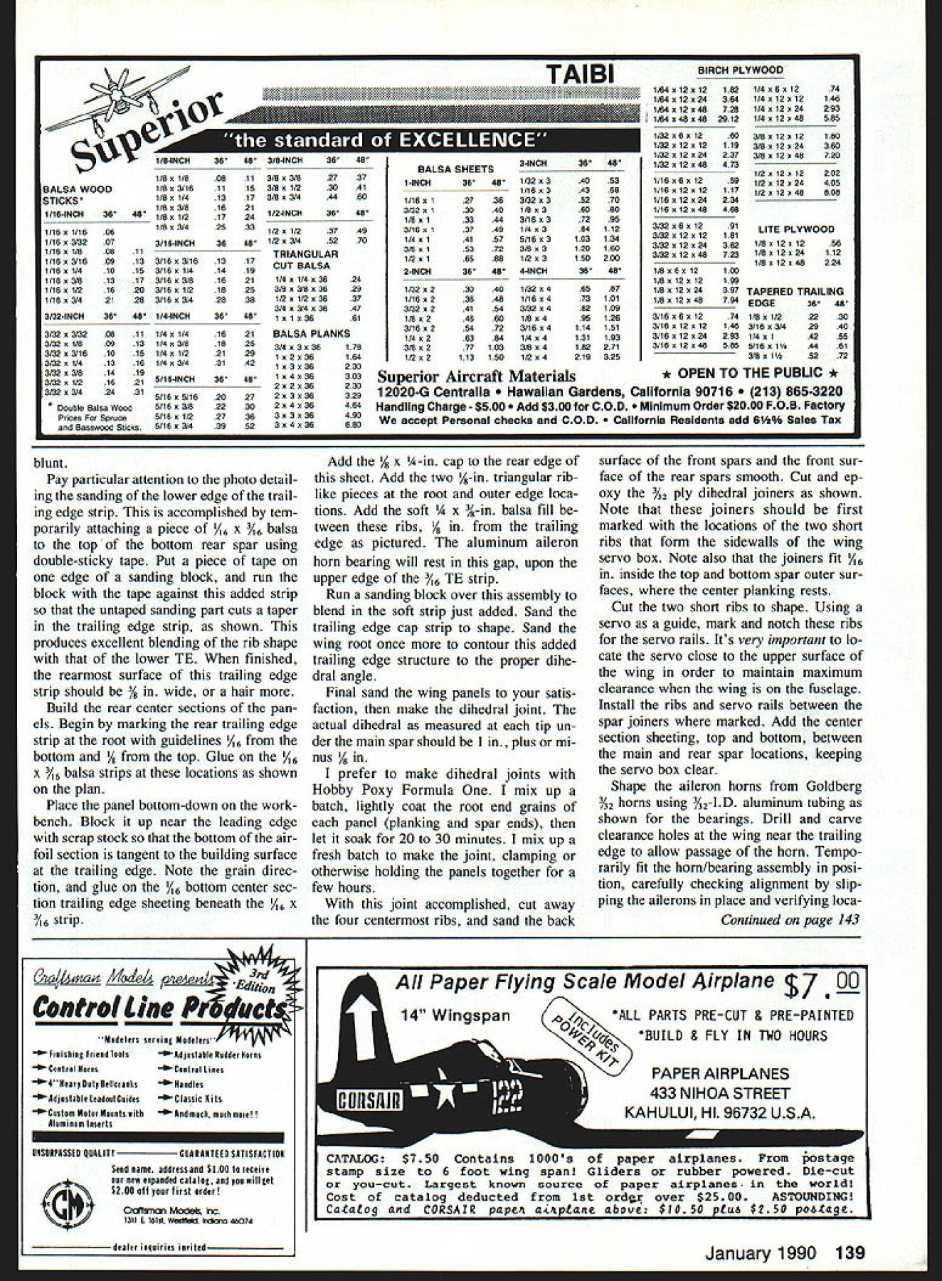
Edition: Model Aviation - 1990/01
Page Numbers: 24, 25, 26, 27, 28, 29, 30, 31, 32, 33, 34, 135, 138, 139, 143, 144, 145
NO OCR TEXT NO OCR TEXT youll get very satisfying results care slight breeze model will economy installations large aile- execute outside loops airplane takes rons permit easy consecutive rolls Inside definite directed attitude moderate loops piece cake little winds handling easily Just touch down stick need sustained verted flight itll climb atti tude light breeze Performance well beyond trainer en velope model does spins snaps has quite wide speed range Landings very controlled Given some head wind takeoffs short grass possible low-end power systems Im bi ased think Skyvolt terrific flier As youd expect installing cobalt 15s further augments performance Feed 150 over 200 watts power youve created whole new machine higher power end airplane fast er takes off does touch-and-goes easily executes very impressive square inside loops sure maneu vers within models range have yet try Whatever power combination choose Skyvolt remember everything works much better speed control Dont build model Construction As good Electric structural design emphasizes strength needed light weight everywhere Building tech niques generally familiar straightfor 26 Model Aviation Two different-sized motors accompanied V-block cradles blocks can glued onto motor mount plate inter changed motors have two strips sandpaper attached bottom pre vent slipping Use 1A-in single-sided foam tape cradle edges soft motor set Skyvolt its bare bones showing sticks takes put together keep togesner stage construction no equipment installed should weigh 10 11 ounces Left peek inside cabin Skyvolt showing 10 1 uu-mAh cells position two hidden under windshield receiver double-sticky Veicroed former F3 250-mAh receiver battery pack Veicroed floor under receiver Right Great Planes Gold Fire motor shown strapped place Note fuse visible behind motor speed controller mounted deep down against floor NO OCR TEXT ward basically follow construction guidelines Electrics discussed About Electrics Part Eight April 1984 Model Aviation previously refer enced Spectra article However few assembly procedures Ive devised unique Skyvolt Tail surfaces like start off simple structures Theyre built assem bled quickly feel lot has accomplished very little time Select straight lightweight balsa edges Note balsa edges rud der elevator taper sanded hinge line Follow procedure plan use tape hinges prototype Scotch catalog #190 clear plastic tape 4 4L III__ = I W NG PLANTOP VIEW HID BALSA SOEE WISH RIBS I II FBeALAAr S IIDENTER SECT TEVAR BOTTOM itIi HR TLB BALSA II I SABDOIIW TAR tO x\\\HH I/ AT EDENVIA BALSA SNEEr lop BBALSA WING TIP OVERBOTTOM -NET IN AT A5MAIN SPARALTERNATE TAR N BOTTOMREARFRONT HIS BALSA~fI2IL1I1il IHIA BALSA AlSO HO BALSASWEET I2 CENTER SECTION WEBS WISH BOWEL OSLO SOWN LOCATIONS HR LITE PLOIHBBALSA SHEET FUSELAGE RARE ABATT SUPPORTBABE BASE 2IHABALSO STEET NOSE DOUBLERWING SADDLEROTOOB STARTS H~ 0 BIDET 1_____Al 1 LG MOUNTVIN SLTWOOO LARGER CASEOOSS CS GALS PIRE VG L2 SINALE NERO MOTOR MOUNT V BLOCKS ALL BDONTS SOWN ARE Il/A LWNGI in wide hardware stationery stores See Model Aviation April 1984 prefer employ conventional hinging techniques sand hinged edges accord ingly sure take account hinging method chosen positioning halfcircle cutout rudder clear spruce elevator joiner piece Also sure pencil guide marks stabilizer sembly necessary mounting fin/rudder stab assembly latter fuselage Mark drill /2 holes horn mounting screws rudder elevator shown completed tail structure should weigh about / oz uncovered Fuselage Begin selecting two pieces /16 x 4 x 36-in medium balsa Together should weigh about 15 20 oz Af ter joining sheets double-sticky tape three four places Scotch brand #665 double-stick transparent tape sim ilar product trim edge stacked sides straight using metal straightedge guideline straight-cut balsa side edge IHB BALSA SOEET FRONT I 11 REAR I WING WEBS INS PLOWOSOHB NHA TATCH POORETSCOO HANA GA LSAIHBOIHCI SSWPE os-JELL STOWSCR0 OHE OS N ISHA BALSA C -LA BOTAR ESTOSTELL110 GAL PASELOGE BIDEHaLITEPLC SECTION A-AHOBLITE PLO HIS BALSA SHEET10010 CROSS MAINLAIODISS GEAR becomes fuselage bottom edge Outline fuselage profile balsa prefer using Pilot brand precise rolling ball extrafine pens cut side edge fuselage profile size shape finished pair cut outline typically weighs about 1 oz Mark drill /I6 wing hold-down dowel holes using sharpened brass tube same dimension Separate two side edges remove tape residue lay side sheets accurately over plan side view bottom straight edge bot tom straight edge Using ruler mark sheet sides vertical lines using plan phantoms locate necessary former upright positions shown marking exercise greatly simplifies fu selage construction significantly en hances accuracy alignment during assembly Glue R-in-sq longerons verti cals taking particular care space ac curately former locations use scrap actual former material spacer-guide position gaps formers will placed Add wider 28 Model Aviation Close-up details 0016 x -in brass strip washer plates under 2-56 ma chine screws thread yellow inners Sullivan Golden Rod around mo tor structure air intake well aileron servo linkage mounted wing shows Futaba output wheel S 33 servo pushrods forward off set holes differential aileron throw allows up aileron motion down Clear plastic tape holds servo wire against wing out harms way Full-Size Plans Available See Page 188 S/IS SO RALAG DT~1 L L ] I____ LISRALSA TBUILDING JIG-Il ooROOT SIR Tier AEBTOAL /A BALSA TE ARS TAP SHEET WEDE-]S/A GA S - j GRAINBOTTOMIL ALEROS NDII OLGA DETAILIA ANGELOlA GA HARD GAPIIBALSA SPARS AL TJGEolODE 9 BATTOR OTOj -\\YI7 AOU TORSO EGOS 5181K ODES ALIT JANT AILERONADA PLO BOTTOM SAP UT CAPI/SAG BALSA SELAGE TOP VIEW 5 BALSAOAT OAT PAR NEROG RPLT4Y7\ ASERTDTRATkNN /7 AIRBALSA I/IA SALSA___NADERI/B BIRCA BODEPLOMOAD 7 I/IS BALSA I/ID BALSAMOTOR MOUNT RON HORN BADE A0/52 PLO USA PLOSAND ATE REAR SPAR JOINER ORSOCE / S BALSA-----I--- /MS S/A NOPT BALSA SAGE ISSC ____________ ~OINEOTTIP WING CENTER DETAIL /R BALSAMAIN RARE 2C WING RIB PATTERNS AILEBGN OSROIDI/B BALSA ROBOT 5/IS NS TIP RIB I/A N/B NA BALSACATBGTTHM SINGE OGRE LOADING ROADRIB DETAIL APPUP AGAINST ODE OWE WING TIP PATTERN REAR LA TOGA/IN 5/SOT RID MARIO WIRE TRCSTOCA FINAL NGAPE GA REAR SERGO TO RE I READ SOS/IT IN BSAND TA RAIN STRUT TRODEASELAAECOLLARS LG PATTERNDIG PCOGILGEAD FUSELAGE VIE AGCD PLOWOCO rBOWEL5I/IA S/IATAILGAROLVIEW SSALSA SOGIPSREARING IIDlES I/GRALSA II I II II I II IG __________________________II__ ____________________________________________________________[v32][b32813344200]]AD ES 8I/S SI/S I/IS BALSGA I/ISS 0/IDDALSA 0/AIDSIR/ NADERA/IDS[ I/B SI/ALiDS I/ABALSA ARBALSA SSDEOSADDLE TAPEOlDS I/G RING SADDLEI/B RO I/B NA BALSALIGGADRONS II I/ID I/A BALSAI/G NAPASO SIDE/FIN i RUD G BALSAGERTICAL _______________SDEET /0 GERESUPPORTSICR ASEEP_______ IIHALSA S/BPSBALSA S/BPSSOEDO lI/AS 0/BADS fliS/ISSECT B-BI/BS A/GA5/0/BALSA HE-A BALSAPSCRAP BALSAII I/GSA BALSA lII/GDLOIIBALSAI] I -C IIIOI- fL~IITBAR /RI/S BALSA U-I I4J/OORNDTDARI/I0/BAL5ASAED UR IIRS I/A IIGDBALSA FUSELAGE VIEW OPECIFICATIONG / ELEVATOR TRFSTOOR / II SCMS SUB BALSA BELOW STA ILIZER_ 3/A GALSA --ELDA BORN STEET I IBOTTOMI 0/ID BALSAETAPE TODETLEI \56BSAI BALSA S/A DUCT AIDE S/ID NA CRS S/IS 5 AG 0'ASAS0/ MODEL AVIATION S KY VOLT DESIGNED BY BOB KOPSKI TRACING BY 30E DEMARCO IALL RIBNTS RESERVED A-in-thick strips pieces undrilled /8-in wing saddle doublers /8-in Lite Ply bottom nose doublers Go over entire structure sanding block get rid bumps irregularities Drill through wing saddle doublers dowel locations using holes side sheet guides Add A-in-sq hard balsa pieces landing gear area /8 x %-in strips hatch area front triangle fill stock light balsa in side battery guides shown Mark cut out pushrod exits Block sand edges both sides match Cut out formers servo tray motor mount pieces landing gear plate materials indicated servos other S-33s shown youll need modify servo mounting plate accord ingly Only microservos recommended model Note former F4 has some added balsa strip material front back top wing saddle V A6 x A-in strip back depressed /16 below V provide rest fuselage top sheeting just aft former location Begin boxing up fuselage method described several possible approaches Position glue form ers side using small triangle -Hi-TROD Left Details tail wheel steering linkage pushrod goes directly rudder via short Golden Rod psuedo turnbuckle wheel collar pushrod end tees off linkage 4-40 Stud bolt ball link Another wheel collar silver soldered tail wheel strut has similar stud/ball link arrangement During final assembly just connect two ball links shown Right finished stabilizer/elevator structure Note line marking guide fin attachment after covering Similar marks bottom will assist attach ment tail assembly fuselage Make certain remove covering material may have adhered between line marks January 1990 29 Left The completed fin rudder framework triangle stock side bottom yet added Above Initial steps constructing fuselage two side pieces bottom-to-bottom show location lines drawn place lines make life lot easier positioning formers accurate assembly structural alignment sure orthogonality Bring remaining side substructure position against formers clamp rubberband ap propriate everything seems aligned apply CyA cyanoacrylate appropri ate places Install /8 x 3A-in battery support strips between formers F2 F3 strips serve dual function First per mit air scooped under motor mount ing plate pass through lower cutout former F2 flow up among battery cells pass over top former F3 exit rear opening fuselage Second hold battery pack upright fuselage maintain high center-ofgravity vertical location improves execution roll maneuver battery support strips place block snad fuselage bottom until flat install A6 landing gear plate gluing well attach bottom sheeting former F2 beyond F4 shown Position fuselage over plan top view pin securely Use some scrap /16-thick pieces block up rear ends fuselage sides away building surface Draw sides together rear following top view guideline Make crosspieces favorite method cut single strip /16 x /2-in balsa length crosspiece location cut half lengthwise make two A-in-wide crosspieces equal length Install crosspieces top bottom locations shown Remember raise bottom ones /16 Use small triangle clamps necessary assure fuselage squareness integrity assembly stall rearmost top ply tail wheel strut bearing plate shown Add /16 top sheet trailing edge stock stabilizer leading edge Add top sheet just aft F4 depress ing F4 form juxtaposed /16 x A-in strip previously placed former V shape blending flat shape aft point Add top edge /16 x A-in longeron caps A6 x /6 crosspiece caps Lift fuselage structure work bench turn over install bottom tail wheel strut bearing plate Add bot tom longeron crosspiece caps Notice balsa intersections form multisur faced jointsan indication exceptionally strong light construction Make rear hatch rest plate adding /8 x /2-in balsa cross strip between fuselage sides rear hatch open ing against F2 front Install balsa windshield using light easy-to-form /16 A-grain sheet Cut small notches /16 wide /8 deep fuselage sides very bottom windshield will inserted Install /8 x 5A6 fuselage crosspiece top previously installed hatch rest against windshield front edge Trim %2 front edge right fuselage side sets up nose correspond two degrees right 30 Model Aviation finished fuselage sides formers ready assembly fuselage front bottom should also shaped according plan protile before actual assembly undertaken ueiaiis rearward side F2 showing AG x 4-in strip following gentle V former top strip set Ae below former top strip front-facing side 1-in material provides sad dle area wing trailing edge rest Left A look upside-down fuselage during installation landing gear mounting plate servo tray has already installed Right fuselage sides have pulled together nose glued motor mount thin bead CyA top bottom thrust indicated Make up appropriate V block fit particular motor shown plan Loosely attach motor mount plate proper amount right thrust spot gluing using doublesticky tape Minimal attachment allows easy removal replacement should decide change power systems later date motor clamps ensure secure loca tion motor-holding V-blocks Pull fuselage front sides together against motor mounting plate rub berbands clamps latter should rest squarely top edges A-in Lite Ply bottom side doublers Check out thing alignment glue motor plate place Install top / x -in balsa front crosspiece /8 x -in topmost crosspiece Block sand very front fu selage taking care get edges flat preserving side thrust dimension Install A-in-thick cross-laminated sheet balsa nose former Fl Complete bottom fuselage sheeting front landing gear plate Note sheeting continuous point slightly yond rear edge motor mount plate Partial narrow sheeting continues along two lower fuselage edges well ward area however later sanded blend fuselage front simple hatch used Skyvolt has proven easily made structure functions very well field Make hatch cross-grained lightweight A-in balsa shown cutting trimming fit neatly front top fuselage hatch re cess its just right size shape bend upside-down over scrap A-in strip shown photos Attach two /32 ply strips shown CyA making sure extend about /16 past front edge balsa hatch Like projecting toes strips tuck under neath uppermost forward fuselage A-in balsa plate Note strips also cut back rear edge hatch clear rear hatch rest plate rear hatch held down hatch recess nylon landing gear strap functions catch bowed hatch pops up catch moved clear Give completed fuselage thorough sanding Take time round cor ner edges nose former etc gener ously possible Youll laying foun dation very eye-appealing model covered Assemble landing gear trial fit place ply mounting plate Use %-in No 2 sheet metal screws /16 pilot holes secure nylon landing gear straps certain drill holes /l6 inJanuary 1990 31 Left Close-up view showing details fuselage side subassem blies nose back former F2 Above Fuselage begins take shape way assemble fuselage install form ers side first sure proper position square before installing other side Triangle ensures vertical alignment Details ot tne aimost-tinisnea tuseiage nose section ready nose block installation close-up view fuselage sticks Assembly actually difficult sounds text Multisurtaced loints very strong Theres no need sheet top bottom landing gear made up %-in-dia music wire Locate straps same di mensional relationship building block fuselage front wire should vertical Bring up rear strut bend nec essary bind copper wire solder joints assembly very strong Trial fitting landing gear Use /8-in gear straps front strut %2-in rear struts Use #2 x 3/8-in sheet metal screws set 3As inside fuselage sur face Epoxy fiberglass matting over gear mounting plate Cut out lightening hole epoxy set before final sembly gear visible structure side fuselage battery support rails ward outside fuselage dimensions meet center 4-in hard balsa strips underneath ply plate Bend install tail strut centered /16 bearing holes top bottom ply plates shown rib-to-trailing-edge assembly Use 3A6-in stock under ribs piece V2-in-sq steel key stock weight down structure its assembled pictured TE jigs shown plans help supporting trailing edge its CyAd ribs Details tail wheel strut assembly Wheel collars top bottom keep strut place top collar setscrew can made accessible either through rear opening through notch may cut fuselage side under stabilizer 32 Model Aviation Left Close-up windshield area hatch cover recess vis ible Follow text photo fashion yours same way Above simple functional hatch cover Pin cross-grained 1/i balsa sheet over 4-in strip Pin down ends sheet Add 1A2 x %-in-wide ply strips CyA position Note exten sions strips front cutbacks back hatch photo shows springy hatch cover tensioned place plastic landing gear hold downs yet installed makes simple positive hatch installation look air scoop structure formed bottom motor mounting plate bottom sheeting faired curved fu selage sides nose block fashioned laminating two pieces 1/8-in balsa cross grain sanding final shape Trial mount servos make rud der elevator pushrods Remove trialfitted hardware put drop thin CyA screw holes harden threads Fi nal sand fuselage set aside covering point structure should weigh very nearly 3/2 OZ ailerons incorporate some unusual con struction techniques deserve some de tailing like build before conWing center short rib notches servo rails Use actual servo notch guide Locate servo deep wing allow motor battery clearance wing place structing wings Theyre fun assem ble Since ailerons relatively large area theyd heavy built out solid chunks wood conventional way gained needed lightness making hollow ailerons designed very strong twist resistant well ailerons require less two full sheets %6 x 3 x 36-in balsa prefer Cgrain sheets Alternatively can use 4in-wide stock rate choose light est wood can find Study photos well Begin cutting Lite Ply template l%2 wide about 6 long Cut end balsa sheets 450 angle proceed slice off bottom trailing edge sanding operation described text 14w x 3A6-in tem porary balsa strip double-sticky-taped over bottom rear spar sanding block has tape cover rides strip during sanding simple step raises sanding block high enough clear ribs fairing trailing edge close-up shot 1Ae X /i6-ifl strip initial step building rear wing center structure Its location crit ical position accurately possible bottom view completed wing center section Note aileron servo cutout installed aileron torque rods pieces using template stop block pinned work surface shown Cut off necessary number pieces laid end end total length will enough make surface bottom both ailerons January 1990 33 main spar webs being installed left wing /2-in-sq steel key stock bar weights down structure against temporary 3A6-in balsa strips under ribs negate warping vetatis wing structure during assembly major part internal right wing struc ture completed photo Note tapered spruce rear spar doubler place Assembly rear center structure underway piece %-in tubing placed temporarily establish location x 3A-in strip behind tubing rests previously installed A6 x %6-in strip outside trailing edge strip Since top surfaces must little wider bottoms theyre made lit tle differently Add /16 wood wire spacer between template stop block cutting second sheet results %2-wide sheets will used aileron top surfaces Pin metal straightedge place po sition /8 x -in balsa aileron trailing edge TE cap against straightedge pin strip place four inches careful note grain direction aileron Begin placing narrower bottom balsa sheets ones cut first against trailing edge stock pictured Sand needed good fit around Using piece wood hold small sheets tightly down against building sur face time run thin CyA along sheet/TE-strip joint Dont glue mating edges sheets together generally makes CyA mess underneath Instead use short lengths /16 x 4-in stock thick CyA shown connect sheets other sure joiners located off fore/aft cen ter shown wont interfere similar pieces installed under neath top sheets later front sheet leading edges ragged along aileron length remove subas sembly board carefully sand smooth long sanding block Af Continued page 135 Left aileron torque rods installed %-in-OD aluminum bearings Position tubes carefully temporarily tape ailerons place correct alignment Right wings being joined together epoxy dihedral joint Use rubberbands epoxy sets Left plywood wing dihedral joiner being epoxied place Clamp firmly place until epoxy sets Right dihedral bracing servo box structure detailed text also similar %2-in plywood dihedral brace inside surface rear spar template accurately slicing aileron sheeting 45 Butt sheeting against block let template guide knife Top sheeting wider bottom See text Root-end shot completed ailerons slip tubes place Note 1/a4-in plywood reinforcements top bottom Left Attaching aileron leading edge / x -in hardwood strip wood blocks hold strip vertical CyA applied Move along entire length aileron manner being careful glue blocks Right Top aileron sheeting being installed Note short e x 3A6-in balsa toe sheet being installed sheeting goes against trailing edge top leading edge Note top bottom sheeting cross-grained Use thick CyA balsa toes leading edge thin CyA sheeting attaches trailing edge 34 Model Aviation SR Battery Packs Make Clean Sweep 89 KRC Electric Fly! Saturday Sunday September 16 17 10th annual KRC Electric Fly held Quakertown PA year two different types endurance events held Saturday Sunday Although weather miserable Saturday up last down event held 12 contestants participated four top finishers using SR packs First place won using SR 1250 Series Magnum pack second place won using SR 1250 Series Magnum pack third place won using SR 1800 Series Magnum pack fourth place won using SR 900 Series Max pack Sunday weather much better different type endurance event held Instead simply longest possible flight contestant made series 4 minute flights 2 minute period between flights retrieve planes allowed recharge change battery packs between flights contestant logged highest number 4 minute flights plus number seconds last flight won objective minimize affect thermals outcome event again SR Battery packs made clean sweep event First place won using SR 1250 Series Magnum pack second place won using SR 1000 Series Max pack third place won using SR 1250 Series Magnum pack As can see comes Electric Power battery packs SR Packs cant beat Two years ago SR recognized need series cells designed exclusively electric flier new series would have give electric fliers longest possible motor runs lowest possible weight new SR Magnum Series cells outgrowth research development Magnum Series cells pack 40% 50% capacity cell increasing its size weight Magnum cells primarily designed Sport applications maximum current load 12 15 amps intermittent applications SRs EP Max Pack Cells other hand designed lowest possible internal impedance could handle extremely high current loads continuous discharge rates 15 30 amps SR Max Pack cells best choice rather Magnum cells addition Electric Flight battery packs SR now Stop source Electric Flight supplies SR now stocks motors props chargers wire connectors switches just about anything else might need Electric Flight addition everyone SR will too happy answer questions help solve problems might have place order ask question can reach us calling Hotline 516-286-0079 between 9am 5pm Monday through Friday youd like us send literature send self addressed business size envelope 50 cents postage SR Batteries Inc Box 287 Bellport NY 11713 -ADVERTISEMENTSafety/Preston Continued page 22 agreed way thinking Back May 1980 Safety column published list flying field rules compiled rules differ ent clubs list contained 43 different rules intention clubs should select believed applied operations list did ad dress pets Rule #39 Pets shall con fined spectator area did specifically address kids However two rules applying adults seem equally appropriate kids Rule #11 Spectators welcome must remain designated area lieve should also apply young chil dren unless escorted parent club member gnated area spectators does include pit area flight line Rule #21 Pilots must stand marked pilots box Only pilots instruc tors spottersare permitted stand pilots box dont believe children toddler age likely qualified pi lots instructors spotters other words dont believe toddlers should permitted flight line So now have opinion right ful place children flying field However please dont misunderstand am very much favor hobby being family affair possible Bring kids flying field means own protection please dont let roam around unsupervised As column points out month accidents hap pen Lets have victims children encourage anyone wishing express different viewpoint concerning issue write Meanwhile lets have safe month Skyvolt/Kopski Continued page 34 ter repinning place add hard /16 x -in leading edge strip top ai leron bottom sheets shown Making sure strip perpendicular surface easily done small blocks pictured spread thin CyA along joint Take care glue blocks process Lightly run felt-tip marking pen over top edge leading edge strip color Using small sanding block tape covering corner edge carefi1ly sand away darkened top edge leading edge strip As maneuver tape-covered corner block bottom sheet-TE joint color disappears youll know leading edge top edge tapered proper angle Its important oversand very front edge strip must remain /4 high Y6 building sur face Fill root end of aileron ta Continued page 138 IA ES MILLS METALS BOOKS PRECISION INSTRUMENTS COMPLETE CATALOG $2 00 1 OUls 0, 4VPDIU FULl Cl S 2100 M So Road Spo oqt old Oh o 45505 mpa 322 8562 January 1990 135 THE WIREMASTER o bender/coder extra large handle bends 118-114 coils 5/ 32-3116 music wire Wire creep eliminated ANTI-KREEP WIRE LOCIV free catalog has hundreds new items free miCro bender offer JCM COMPANY 114 Washington Ter. Waukegan IL 60085 IS* WE BUILD YOUR HELl TEST YOUR HELl YOUR HELl I1- Lehighton Pa 18235 WRITE OR CALL FOR INFORMATION Skyvolt/Kopski Continued page 135 pered -in balsa Begin laying top sheets place applying CyA go along Make absolutely certain top sheets run cross-grained lower sheets sure add /16 x -in joiner top sheet piece installed best done first attaching about half length joiner top sheet piece youre about install positioning assem bly place against previously installed unit adhering thick CyA sounds difficult isnt Studying photo should give confidence Remove aileron structures bench square up ends cap outer tips A-in sheet Rough carve trailing edge strips sand blend aileron taper Sand aileron its entirety removing irregularities leading edge top bottom sur faces caveat Remember lightI II II II Washable ed Cap Sunglasses nip up/Down Adjust In/Out Snap On/Off Imprints Available Ultra Violet Protected Please send _____________ caps Ive enclosed I @ $795 plus $2 shipping handling I Lets Colors 0 Amber 0 Smoke blue Cap Colors LI Black LI White LI Yellow I EiJ Green LI Navy blue LI Royal blue LIMaroon LIGrey El Red LI Please send information about imprinting PLEASE PRINTI II II II II I_____________ ___I II Name Address city StateZip RETURN WITH CHECK OR MONEY ORDER ONLY TO PIN-NIK SALES PO Box 647 Ravenna OH 44266 L weight wood sands away too easily Take care oversand flat surfaces learned hard way goal no re tain basic aileron thickness Notch root ends shown accu rately CyA A-in length %2-ID alu minum tubing place Add root top bottom pieces 4 ply Make sure inside tubing remains free adhe sive aileron horn slip tubes essential smooth operation ailerons wing itself requires less unusual build ing techniques should clear plan pays begin accurately marking rib locations leading trailing edge strips using small square triangle ribs cut out begin assembly locating main bottom spruce spar over plan As aileron trailing edge piece use metal straightedge Position spare piece 3/16-sq balsa strip temporary support under ribs about 3/4 forward trailing edge lo cation adjust necessary Place three center root ribs position spar pin posi tion After checking theyre accurately positioned apply CyA rib/spar joints Bring leading edge piece po sition against ribs using marks ac curately locate ribs hand hold rib place CyA joints trailing edge should firm straight strip /e x /16 balsa like cut own strips sheet stock until come out straight Bring trailing edge piece up against ribs using balsa trail ing edge jigs shown support rib top edges should perfectly flush top trailing edge strip CyA rib trail ing edge joints locations marked TE center section ribs course cut thinner accommodate top bottom center section sheeting keep mind setting place Take spe cial care setting A-in root ribs using dihedral angle guide given plan Cut out guide glue heavier card stock trim shape before using Get ting rib angle right will save lot grief later Install false ribs Slip place tween leading edge main bottom spar line up CyA place Install main spar webs add top main spruce spar Install rear top balsa spar tapered spruce spar dou bler Remove wing panel board flip over Install rear spar webs bottom rear spar tapered spruce spar doubler Complete top bottom center section sheeting forward main spar rearward rear spar between spars Add A-in tip plates both panels assembled stage sand root ends large flat sanding block before trial fitting dihedral joint Continue sand carefully achieve good fit correct dihedral Carefully sand leading edge shape noting very little material removed top somewhat bottom ribs make contact Also note very leading point leading edge very slightly rounded dont make 138 Model Aviation 4b4 415 342 5581 GOLDEN GATE HOBBIES PO BOX 282005 SAN FRANCISCO CA 94128 M/C OR COD CATALOG $ 200 OR FREE WITH ORDERS HATORI BLUEPRINT SHOWS ALL EXHAUST ITEMS FULL SIZE 2FT X 4FT $ 5 HA TORI RA DIGICON M-MSK WE NEED DEALERS WHEN YOU FORGET\OUR UNITS REMEMBER RC System NICd Batteries chargers need packagel Cycler-Chargec *23996 Fits 48V Rx 96V Tx packsPlus $6 S&H Others available write call TrIckIer*34961Regular Model . *4695 ForPlus $3 S&Hsge si%iFor field kit sinaiPlus $3 S&H Mue electric boat batteriesSpecify 612 24V Heavy Duty Model 6 sport winch large boat andPlus $4 S&H electric power charging batteriesSpecify 6 2V CaRa Productssselomasen PO Box 221 605-987-5924DeaiernqaneswwiedCanton SD 57013 cO& 4 Rrh Stuff First Step Model Airplau Simple Simon Airplane Co PO Box 18 East Lonameadow MA 01028 4135923615 BALSA WOOD STiCKS 1/16-INCH3648 1/1601/1606 1/163/3207 1/1601/808 1/1603/1609 1/1601/410 1/163/813 1/1601/216 1/1603/421 TAIBI 1/8-INCH3648 3/8-INCH3648 1/601/808113/803/8 1/803/1611153/8o1/2 1/80 1/413173/8 3/4 1/80 3/81621 _____________________ 1/801/21724 1/8 0 3/42533 3/18-INCH3648 11 133/1603/181317 153/160 1/41418 173/16x3/81621 203/1601/21826 283/16 0 3/42836 3/32-INCH3648 1/4-INCH3648 3/323/3209111/40 1/41621 3/32 o1/809131/4 r3/81820 3/323/1610151/4 rl/22129 3/3201/413161/403/43142 3/3203/81419 3/3201/216218/16-INCH3648 3/32 0 3/42431 5/1605/162027 Doable Balsa Wood5/16 0 3/82230 Pnces Spruce5/16 0 1/22736 Basswood Sticks 5/16 0 3/43952 2737 3041 4480 1/2-INCH3648 1/20 1/23749 1/203/45270 TRIANGULAR CUT BALSA 1/401/403624 3/803/803628 1/2o1/2o3637 3/403/403047 10103661 BALSA PLANKS 3/403036178 102036194 1o3o36230 104030303 2o2o36230 203030329 204036464 3o3o36490 3o4o36680 BALSA SHEETS 1-INCH3646 11160 12738 3/32013040 1/8 0 13344 3/160 13748 1/4o 14107 3/8 0 15372 1/2 0 16589 2-INCH3648 1/32023040 I/16o23648 3/32 0 24154 1/8u24680 3/16o25472 1/4028384 3/80277103 1/202113150 3-INCH3648 1/32034053 1/16034358 3/32 0 35270 1/8036080 3/16 0 37295 1/40384112 5/1603103134 3/803120160 1/203150200 4-INCH3648 1/32048587 1/160473101 3/32 0482109 1/80495128 3/1604114151 1/404131183 3/804182271 1/2 04219325 BIRCH PLYWOOD 1/84012012182 1/84012024384 1/640 12049728 1/640480492912 1/320601260 1/32012012119 1/320 12024237 1/320 12048473 1/160601259 1/180120 12117 1/160 12024234 1/160 12049466 3/320801291 3/320 12012181 3/32 0 12 0 24362 3/32012049723 1/8060 12100 1/8012012199 1/80 12024397 1/8o12o49784 3/180801274 3/160120 12148 3/160 12024293 3/180 12048985 1/40601274 1/4o12o12144 1/4 0 12024293 1/4012048585 3/8o12o12180 3/8012024360 3/8012048720 1/2 0 12o 12202 1/2 0 12024405 1/2012048808 LITE PLYWOOD 1/8o12a1256 1/80 12024112 1/8012048224 TAPERED TRAILING EDGE3646 1/80 1/22230 3/18 0 3/42940 1/4 0 14255 5/1601144481 3/801145272 * OPEN TO THE PUBLIC * Superior Aircraft Materials 1 2020-G Centralla iian Gardens California 90716 865-3220 Handling Charge -$500 $300 COD mum Order $2000 FOB Factory accept Personal checks COD fornia Residents add 6% Sales Tax blunt Pay particular attention photo detail ing sanding lower edge trail ing edge strip accomplished tem porarily attaching piece /16 x /o6 balsa top bottom rear spar using double-sticky tape Put piece tape edge sanding block run block tape against added strip untaped sanding part cuts taper trailing edge strip shown produces excellent blending rib shape lower TE finished rearmost surface trailing edge strip should % wide hair Build rear center sections pan els Begin marking rear trailing edge strip root guidelines /16 bottom / top Glue /16 x 3/I6 balsa strips locations shown plan Place panel bottom-down work bench Block up near leading edge scrap stock bottom air foil section tangent building surface trailing edge Note grain direc tion glue /16 bottom center sec tion trailing edge sheeting beneath /I6 x /I6 strip Add % x A-in cap rear edge sheet Add two A-in triangular riblike pieces root outer edge loca tions Add soft x %-in balsa fill tween ribs /8 trailing edge pictured aluminum aileron horn bearing will rest gap upon upper edge /I6 TE strip Run sanding block over assembly blend soft strip just added Sand trailing edge cap strip shape Sand wing root once contour added trailing edge structure proper dihe dral angle Final sand wing panels satis faction make dihedral joint actual dihedral measured tip un der main spar should plus mi nus /8 prefer make dihedral joints Hobby Poxy Formula mix up batch lightly coat root end grains panel planking spar ends let soak 20 30 minutes mix up fresh batch make joint clamping otherwise holding panels together few hours joint accomplished cut away four centermost ribs sand back surface front spars front sur face rear spars smooth Cut ep oxy 3/ ply dihedral joiners shown Note joiners should first marked locations two short ribs form sidewalls wing servo box Note also joiners fit /16 inside top bottom spar outer sur faces center planking rests Cut two short ribs shape Using servo guide mark notch ribs servo rails Its very important lo cate servo close upper surface wing order maintain maximum clearance wing fuselage Install ribs servo rails between spar joiners marked Add center section sheeting top bottom between main rear spar locations keeping servo box clear Shape aileron horns Goldberg Y32 horns using %2-ID aluminum tubing shown bearings Drill carve clearance holes wing near trailing edge allow passage horn Tempo rarily fit horn/bearing assembly posi tion carefully checking alignment slip ping ailerons place verifying loca Continued page 143 h LsAA ___3rdk CeatrelLine P1gct*t Modelers eng Mode e Finishing FriendTools88 Control Horns 6 HeavyiutnBeltoranksHandles AdIustahIeLeadoutOuideutlassic kits Custom Motor Moanto much much morel Aluminum Inserts ANSAEPASSLD QUALITYGUA8ANOEEOSATISF8COIAM Send name address SlAG receive Nour new eopaednd catalog will get 52 00 ott first Grdnr fl9 CraftaTian Models Inc 1311 L 1616 8Mn81w60 hro 44074 dealer inqniries incited January 1990 139 Paper Flying Scale Model Airplane $7 MLL PARTS PRE-CUT & PRE-PAINTED BUILD g FLY IN TWO HOURS PAPER AIRPLANES 433 NIHOA STREET KAHULUI HI 96732 USA CATALOG $750 Contains 1000 er airplanes ostage stamp size 6 foot wing span Gliders rubber powered Die-cut youcut Largest known source paper airplanes world Cost catalog deducted 1st ordr over $2500 ASTOUNDING CatizLoQ avid AIR papet uzUtpian#z aboue $1050 peuA $250 pohtage ULTIMATE 10 DASH 300 BIPLANE Fiberglass fuselage balsa-sheeted foam wings Quarter-scale 13 Ibs 62 Span Level 1u MIL-F-8785C ST 3000 Flying Q Power alities Sold reservation $75 refundable deposit includes data package $15 separately Comprehensive kit $554 finished unpainted aircraft $1550 powerplant radio gear included Production limited eight hand-crafted individually numbered aircraft per month Satisfaction guaranteed money back Phone FAX 801-753-1971 VISA MC check no COD DAEDALUS RESEARCH INCORPORATED An award-winning design laboratory e 1983 creating advanced concepts military civilian Unmanned Aerial Vehicles tion freedom movement etc After re moving assembly CyA tube bearings place Make sure horn wires very free-moving before continuing Cut glue position single-piece /64 ply top wing center cover sheet shown being very careful get glue around horns bearings mess up youre big trouble use thick CyA operation spreading carefully Notice nicely ply sheet conforms dihedral shape wing woodwork including ailerons horns should weigh about 6 oz Covering Final sand completed struc ture satisfaction before covering prototype used MonoKote film covering choosing will work Before covering fuselage apply iron-on cloth reinforcement landing gear mount area Use paper towel Xween iron cloth keep stickiness cloth off iron Poke holes cloth screw hole loca tions cover fuselage what ever film desire Cover fin rudder stabilizer el evator wing ailerons separately course dont cover glue joints yet made Hinge moving surfaces Since aile rons relatively large its important check out warps before hing ing Using double-sticky tape attach two short pieces balsa stick top surface root tip sight ailerons signs twist Correct warps detect Tape hinges best ailerons conventional hinges may used tail pieces noted earlier sure set 1/16 gap hair less before applying tape Final assembly Glue fin stab glue entire tail assembly fu selage Mount landing gear wheels tail wheel assembly landing gear hardware total weighed 22/s oz stall radio connect rods link ages check out installation smooth nonbinding operation correct throws etc sure make small notch fuselage side rudder horn throw clearance Install wing servo linkages Note off-center servo wheel pushrod hole lo cations achieve aileron differential Also note short pieces 1 2 yellow ner Golden Rod material used quasi turnbuckles easily adjust rod lengths everything installed except power system components Skyvolt should weigh 22 24 oz Install power system components Note popular seven-cell model car batteries will fitanother difference tween Skyvolt trainer designs pack can adapted pictured re assembling fit battery supports between inside fuselage battery guide strips Note side guide strips finished / x A-in wing sad dle tape hold battery pack snugly Leftover battery compartment space should filled custom-fitted foam blocks further snug pack also ensure incoming air forced among about cells battery pack fit must tight enough hold battery place Skyvolt inverted planes flying inverted pass low enough cut groove ground fin dont want battery banging against aileron servo theres question about snugness install some hooks 71 span 58 length 920 sq wing area 38 o per sq ft wing loading Weight 14 16 lbs Power 80 108- two cycle 12- four cycle F4U CORSAIR Finished fuselage 062 Aircraft Quality ABS over crutch & ply bulkheads bulkheads including % ply firewall installed wing design formed ABS Gull covering makes wing snap build Built up tail feathers Complete hardware decals Complete instruction booklet plans AV/ order call write 7p GM Plastics Inc 7252 Industrial Park Blvd / Mentor Ohio 44060 /216 953-1188 January 1990 143 Electric Flight off Controller Perfect 05 Motors 510 cells month Has Broke Lightweight 12 Adjustable switching money back Soideriess terminal ror easy hookupgooroflteo ON/OFF ContraIl er$2495 Power save weight 20 5ize 22x13x63 v high efficIency 006' toss Add SlOlfoeshipping Colifoesis cesidents odd 65% 1163 Tso Send check mosey order Cowessni11HIgh Sky Fotaha esnierotor o 3929 Kansas St #9 San DiegoCA 92104 COMPETITION ACCESSORIES & CUSTOMIZED K&B ENGINES RACING WHEELS KLOTZ OIL CARBON FIBER SOLID LINES ALL KINDS OF FUEL TUBING FOUR BRANDS OFGLOWPLUGS HARD-TO-FIND HARDWARE OLD TIMER SUPPLIES COILS CONDENSERS NGK & STIlT SPARK PLUGS SILK 12 COLORS QUALITY DOPE BRUSHES 5& 7LOOP 1/4RUBBER BANDS TRANSISTOR IGNITION SYSTEMS RESISTOR HIGH TENSION LEADS 1/2A TEXACO PLA YBOYSR KIT 1/2A TEXACO ENGINES & PARTS KSB & IGNITION TIMERS RUBBER POWER KITS PROPS TISSUE AND OTHER SUPPLIES CYANOACRYLA TES & EPOXIES WHAT bo YOU CALL THE BEST SHETING Tigers MATERIAL FOR FOAM WING CORESkins WWIsoOetlanmeara coot0COy ttsaetaothOocoOt taOttaood tOt scooleIcomoog orogttataoaaflaao OOcsot t05500a aO ateinSet Ooo OS O.t athSaoTlgekl area ma Iroartto aaoooSttmOCoatrasetotoeccoresoaoatoeocsatflareeoeaOne 05Th, CHECK THESE FEATURESComes n following Colors Srtoertrstrengtr tows 5fl5 ratoWaco Ret Superror 0000 oaseElitt teamPolar Wote 051 per sO inn tetrtperastre Stahl 50losiptina SI.e Smooth flingS tttt hoistSIn hellew Superinor res stance tinem Otel Stoerorresstenoeoeweester Easy applo ttw low cost l/A4aS3eOSsee 5tonin 000th V0vo0rototO roOt 0 Phonea 3093423009 WV6 MF6 OttO OSOte 0tCc oreO terltoratureda toot ttt5305cinctttltottttsoosto Ott SO 40 coccinos ltr SENT $400 FOR CATALOGI inotins Resindeots eoe 5 1 /2C0 sa sac WING Mfg 306 E SimmoRs Galesburg IL 61401 upper surfaces side guides loop some rubberbands over pack keep place Install power system wiring using preferred method course will determined choice power components speed control etc should plenty space behind motor fit interconnection goodies As point interest install speed control heat sink airstream enter ing under motor mount plate However take care overly block air passage through F2 Clamp motor place using yel low inners small Sullivan Golden Rods C-clamps Cut rods short about in on side prevent touch ing motor mount plate drawn tight 2-56 screws passed through motor mount plate rod ends Installing draw screws made easier first running 2-56 tap yellow rod material Also screw heads should rest 0016 x -in brass strip washers bottom motor mount plate shown See Model Aviation July August 1987 de tail technique Flying preflight check Rubberband wing place carefully check adequate clearance between motor bat tery pack aileron servo linkage really important however taller l200-mAh cells Correct inadequate clearance find Suggestions include trimming bottom battery rails about using -in wing saddle tape instead /16 size shown using smaller servo remount ing servo deeper wing balance check Depending motor chosen model may tend nose-heavy Balance model main sparnot front behind motor battery less t2 cells can moved fore aft help accomplish bal ancing needed Just sure fill up leftover space foam blocks re check clearance discussed above receiver battery may also relo cated behind servos /16 fuselage bottom sheeting installed rea son use double-sticky Velcro Radio Shack purpose sure coat balsa glue such Ambroid first allow dry sticky part Velcro sticks Lastly else fails re luctant am suggest small amount weight may added very rear fuselage negate stubborn nose-heaviness powered Gold Fire motor seven l2-mAh cells Skyvolt weighs 46 oz all-up Equipped fer rite 15 12 900-mAh cells model weighs 51 oz Most Skyvolts should fall somewhere between limits first flights suggest hand launch just check everything out espe cially recommended lower end power systems Gain some altitude before Statement Ownership Management Circulation Required 39 usc 3685 lA Title Publication Mode/Aviation lB Publication No 087930 2 Date Filing September 28 1989 3 Frequency issue Monthly A No issues published annually 12 B Annual subscription price $1800 4 Complete Mailing Address Known Office Pub lication tstreet city county state ZIP code printers 1810 Samuel Morse Dr Reston VA 22090 5 Complete mailing address headquarters general business offices publisher printer 1810 Samuel Morse Dr Reston VA 22090 6 Full names complete mailing address pub lisher editor managing editor item must left blank Publisher Carl R Wheeley 1810 Samuel Morse Dr Reston VA 22090 Editor Carl R Wheeley 1810 Samuel Morse Dr Reston VA 22090 Managing editor None 7 Owner Academy Model Aeronautics Inc 1810 Samuel Morse Dr Reston VA 22090 8 Known bondholders mortgageea other se curity holders owning holding 1 percent total amount bonds mortgages other securities None 9 For completion nonprofit organizations autho rized mail special rates DMM Section 42312 purpose function nonprofit status organization exempt status Fed eral income tax purposes 1 Has changed during preceding 12 months Extent Nature Circulation 10 Actual AverageNo copNo cop- ies single isissue dur- sue pub ing pre- lished ceding 12 nearest months filing date ATotal No Copies Net Press Run116313129500 BPaid and/or Requested Circulation 1Sales through deal ers carriers street vendors counter sales33553513 2Mail Subscription109588123010 CTotal Paid and/or Re quested Circulation Sum lOBi 1082112943126523 DFree Distribution Mail Carrier Other Means Samples Com plimentary Other Free Copies24542380 ETotal Distribution Sum C D115397128903 FCopies Distributed 1Office use left over unaccounted spoiled after print ing660590 2Returns News Agents2567 G Total Sum E Fl 2should equal net press run shown A116313129500 11 certify statements made cor rect complete Carl R Wheeley Editor Publisher 144 Model Aviation u INVENTORY VERA GES OVER 9000 PROPS I! IMMEDIATE SHIPMENT ON VISA/MC SPECIALISTS IN CUSTOM COX TEE DEE & REED ENGINES 020S 049S 051 074S & 09S ALL CUS TOM & STOCK PARTS VAILABLE INDIVIDUALLY ORDER BY MAIL OR PHONE 819 728-4365 SORRY NO COD VISA & MASTERCARD WELCOME MINIMUM MERCHANDISE ORDER $10OOe SHIPPING & HANDLING FEE $200 FOR INSURANCE ADD $100 STOCK ORDERS SHIPPED WITHIN 24 HRS executing first maneuvers Aileron throw may need adjusted recommend somewhat throw lower power less high-priced systems plans show average throws throw easily changed adjusting position screw-on nylon pieces threaded horns flown fairly aggressively Gold Fire-equipped version turned flight times four 4 minutes Installed fer rite 15 plane flew 4/2-to-five-minute runs Whichever power system youre us ing flights can stretched over seven minutes gentler handling air proper use speed control Good Luck Skyvolt hope have much fun quiet flying hours Ive Please dont hesitate send comments ques tions Id also welcome photos fin ished beauty closing want acknowl edge local modeler Bob Clauss suggest ing models name responding advertisers mention read about Model Aviation Continued page 37 tiller bar normally used nose-wheel steering outboard side wheel inside pant attached pant way #2 sheet metal screws type normally used mounting servos Cutting off excess screw length completed installation Since wanted tiller arm flat against wheel pant drill new hole through tiller bar plastic after pushing out metal wheel collar bore plastic til ler put setscrew bottom can easily get Put wheel collar back place its setscrew hole matching new hole youve just drilled tiller Finally file flat axle wheel pant wont fall off immediately after attaching screw becomes little loose New Porta-Sol kit pocket-size Porta-Sol butane-fueled flameless soldering iron Radio Technique February 88 issue MA page 38 proved very handy tool trip used sorts things like installing connec tort shrinking shrink-tubing insulators putting holes plastic etc point remem ber using solder wire back coil Quadra someone field somewhere fact burns cigarette-lighter Butane can lit sparker built its cap virtu ally windproof makes usable almost anywhere Porta-Sol now offers better versatile kit P-lK containing black Porta-Sol four kinds tools tip cleaner hot stand handy box measuring 15 x 3 x 9 like neat kits put useful tools easily stored pack ages Ive added P-tK van new kit features tools plastic retaining screws permit remove/install tools hot interchangeable older orange model al lowed cool first new internally heated tools heat range equivalent electric sol dering irons 10 60 watts very useful de signs Tools include I Standard %2 tip same size older model Other tip sizes 040 %2 Y6 available $899 2 Hot knife Integral design much thicker X-Acto blade sharp fine cut ting plastic sheet sailcloth etc 3 Pencil torch tiny flame fine soldering etc 4 Hot air gun 3R2-diameter source hot air use shrink tubing taking small wrinkles out MonoKote etc really like tool cause tip small Y16 dia x 1 long has no exposed flame can get down inside things dont touch tip sliding shutter anything after have lit fire As before kit made available ser January 1990 145 Radio Technique/Myers THE TAILGEAR SPJtT PASTERN SPORTSCALE Pat Pend flROVE GROUND RANDLfl4G ABSORB SNK TO AIRFRAME AND SERVO DIFFERERTIAL TEROW FOUSIRLE MAT NE INSTALLED IN Mt EflSTIEO BRACKET BRACKET INTERNAL FuSELAGE MOUNT EAST INSTALLATION EASILY ADJUSTABLE NONBINDING COMPLETE INSTALLATION FACEAGE* Mt 1d Q SMALL iO 1AEDIUM6O LABOE 120 TO CNiDER send ns ~ss andEFLigit Industries size desired sith 610 Th16 Woodnore Lane P&a INCLUDER Chattanooga TN 3Thfl FW4 B4OI FREE CATALOG Best 40 Ever 4 Channel nch Span -Symmetrical Wing 25 - 40 Engine 3 3-1/2 lbs Superior Performance Available Favorite Hobby ShopTi4ewoLeL Guaranteed Satisfaction~- 3925-C SE 45th Court IdE/tsiIuaIhIflAOcala FL 32671 S IA41eL FVI44~d lEE 6943531
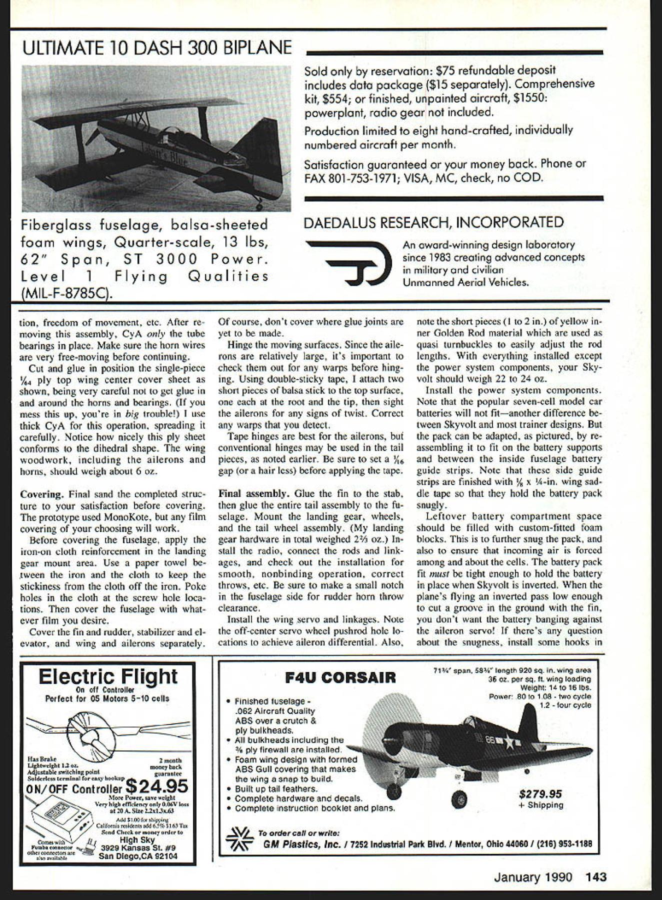
Edition: Model Aviation - 1990/01
Page Numbers: 24, 25, 26, 27, 28, 29, 30, 31, 32, 33, 34, 135, 138, 139, 143, 144, 145
NO OCR TEXT NO OCR TEXT youll get very satisfying results care slight breeze model will economy installations large aile- execute outside loops airplane takes rons permit easy consecutive rolls Inside definite directed attitude moderate loops piece cake little winds handling easily Just touch down stick need sustained verted flight itll climb atti tude light breeze Performance well beyond trainer en velope model does spins snaps has quite wide speed range Landings very controlled Given some head wind takeoffs short grass possible low-end power systems Im bi ased think Skyvolt terrific flier As youd expect installing cobalt 15s further augments performance Feed 150 over 200 watts power youve created whole new machine higher power end airplane fast er takes off does touch-and-goes easily executes very impressive square inside loops sure maneu vers within models range have yet try Whatever power combination choose Skyvolt remember everything works much better speed control Dont build model Construction As good Electric structural design emphasizes strength needed light weight everywhere Building tech niques generally familiar straightfor 26 Model Aviation Two different-sized motors accompanied V-block cradles blocks can glued onto motor mount plate inter changed motors have two strips sandpaper attached bottom pre vent slipping Use 1A-in single-sided foam tape cradle edges soft motor set Skyvolt its bare bones showing sticks takes put together keep togesner stage construction no equipment installed should weigh 10 11 ounces Left peek inside cabin Skyvolt showing 10 1 uu-mAh cells position two hidden under windshield receiver double-sticky Veicroed former F3 250-mAh receiver battery pack Veicroed floor under receiver Right Great Planes Gold Fire motor shown strapped place Note fuse visible behind motor speed controller mounted deep down against floor NO OCR TEXT ward basically follow construction guidelines Electrics discussed About Electrics Part Eight April 1984 Model Aviation previously refer enced Spectra article However few assembly procedures Ive devised unique Skyvolt Tail surfaces like start off simple structures Theyre built assem bled quickly feel lot has accomplished very little time Select straight lightweight balsa edges Note balsa edges rud der elevator taper sanded hinge line Follow procedure plan use tape hinges prototype Scotch catalog #190 clear plastic tape 4 4L III__ = I W NG PLANTOP VIEW HID BALSA SOEE WISH RIBS I II FBeALAAr S IIDENTER SECT TEVAR BOTTOM itIi HR TLB BALSA II I SABDOIIW TAR tO x\\\HH I/ AT EDENVIA BALSA SNEEr lop BBALSA WING TIP OVERBOTTOM -NET IN AT A5MAIN SPARALTERNATE TAR N BOTTOMREARFRONT HIS BALSA~fI2IL1I1il IHIA BALSA AlSO HO BALSASWEET I2 CENTER SECTION WEBS WISH BOWEL OSLO SOWN LOCATIONS HR LITE PLOIHBBALSA SHEET FUSELAGE RARE ABATT SUPPORTBABE BASE 2IHABALSO STEET NOSE DOUBLERWING SADDLEROTOOB STARTS H~ 0 BIDET 1_____Al 1 LG MOUNTVIN SLTWOOO LARGER CASEOOSS CS GALS PIRE VG L2 SINALE NERO MOTOR MOUNT V BLOCKS ALL BDONTS SOWN ARE Il/A LWNGI in wide hardware stationery stores See Model Aviation April 1984 prefer employ conventional hinging techniques sand hinged edges accord ingly sure take account hinging method chosen positioning halfcircle cutout rudder clear spruce elevator joiner piece Also sure pencil guide marks stabilizer sembly necessary mounting fin/rudder stab assembly latter fuselage Mark drill /2 holes horn mounting screws rudder elevator shown completed tail structure should weigh about / oz uncovered Fuselage Begin selecting two pieces /16 x 4 x 36-in medium balsa Together should weigh about 15 20 oz Af ter joining sheets double-sticky tape three four places Scotch brand #665 double-stick transparent tape sim ilar product trim edge stacked sides straight using metal straightedge guideline straight-cut balsa side edge IHB BALSA SOEET FRONT I 11 REAR I WING WEBS INS PLOWOSOHB NHA TATCH POORETSCOO HANA GA LSAIHBOIHCI SSWPE os-JELL STOWSCR0 OHE OS N ISHA BALSA C -LA BOTAR ESTOSTELL110 GAL PASELOGE BIDEHaLITEPLC SECTION A-AHOBLITE PLO HIS BALSA SHEET10010 CROSS MAINLAIODISS GEAR becomes fuselage bottom edge Outline fuselage profile balsa prefer using Pilot brand precise rolling ball extrafine pens cut side edge fuselage profile size shape finished pair cut outline typically weighs about 1 oz Mark drill /I6 wing hold-down dowel holes using sharpened brass tube same dimension Separate two side edges remove tape residue lay side sheets accurately over plan side view bottom straight edge bot tom straight edge Using ruler mark sheet sides vertical lines using plan phantoms locate necessary former upright positions shown marking exercise greatly simplifies fu selage construction significantly en hances accuracy alignment during assembly Glue R-in-sq longerons verti cals taking particular care space ac curately former locations use scrap actual former material spacer-guide position gaps formers will placed Add wider 28 Model Aviation Close-up details 0016 x -in brass strip washer plates under 2-56 ma chine screws thread yellow inners Sullivan Golden Rod around mo tor structure air intake well aileron servo linkage mounted wing shows Futaba output wheel S 33 servo pushrods forward off set holes differential aileron throw allows up aileron motion down Clear plastic tape holds servo wire against wing out harms way Full-Size Plans Available See Page 188 S/IS SO RALAG DT~1 L L ] I____ LISRALSA TBUILDING JIG-Il ooROOT SIR Tier AEBTOAL /A BALSA TE ARS TAP SHEET WEDE-]S/A GA S - j GRAINBOTTOMIL ALEROS NDII OLGA DETAILIA ANGELOlA GA HARD GAPIIBALSA SPARS AL TJGEolODE 9 BATTOR OTOj -\\YI7 AOU TORSO EGOS 5181K ODES ALIT JANT AILERONADA PLO BOTTOM SAP UT CAPI/SAG BALSA SELAGE TOP VIEW 5 BALSAOAT OAT PAR NEROG RPLT4Y7\ ASERTDTRATkNN /7 AIRBALSA I/IA SALSA___NADERI/B BIRCA BODEPLOMOAD 7 I/IS BALSA I/ID BALSAMOTOR MOUNT RON HORN BADE A0/52 PLO USA PLOSAND ATE REAR SPAR JOINER ORSOCE / S BALSA-----I--- /MS S/A NOPT BALSA SAGE ISSC ____________ ~OINEOTTIP WING CENTER DETAIL /R BALSAMAIN RARE 2C WING RIB PATTERNS AILEBGN OSROIDI/B BALSA ROBOT 5/IS NS TIP RIB I/A N/B NA BALSACATBGTTHM SINGE OGRE LOADING ROADRIB DETAIL APPUP AGAINST ODE OWE WING TIP PATTERN REAR LA TOGA/IN 5/SOT RID MARIO WIRE TRCSTOCA FINAL NGAPE GA REAR SERGO TO RE I READ SOS/IT IN BSAND TA RAIN STRUT TRODEASELAAECOLLARS LG PATTERNDIG PCOGILGEAD FUSELAGE VIE AGCD PLOWOCO rBOWEL5I/IA S/IATAILGAROLVIEW SSALSA SOGIPSREARING IIDlES I/GRALSA II I II II I II IG __________________________II__ ____________________________________________________________[v32][b32813344200]]AD ES 8I/S SI/S I/IS BALSGA I/ISS 0/IDDALSA 0/AIDSIR/ NADERA/IDS[ I/B SI/ALiDS I/ABALSA ARBALSA SSDEOSADDLE TAPEOlDS I/G RING SADDLEI/B RO I/B NA BALSALIGGADRONS II I/ID I/A BALSAI/G NAPASO SIDE/FIN i RUD G BALSAGERTICAL _______________SDEET /0 GERESUPPORTSICR ASEEP_______ IIHALSA S/BPSBALSA S/BPSSOEDO lI/AS 0/BADS fliS/ISSECT B-BI/BS A/GA5/0/BALSA HE-A BALSAPSCRAP BALSAII I/GSA BALSA lII/GDLOIIBALSAI] I -C IIIOI- fL~IITBAR /RI/S BALSA U-I I4J/OORNDTDARI/I0/BAL5ASAED UR IIRS I/A IIGDBALSA FUSELAGE VIEW OPECIFICATIONG / ELEVATOR TRFSTOOR / II SCMS SUB BALSA BELOW STA ILIZER_ 3/A GALSA --ELDA BORN STEET I IBOTTOMI 0/ID BALSAETAPE TODETLEI \56BSAI BALSA S/A DUCT AIDE S/ID NA CRS S/IS 5 AG 0'ASAS0/ MODEL AVIATION S KY VOLT DESIGNED BY BOB KOPSKI TRACING BY 30E DEMARCO IALL RIBNTS RESERVED A-in-thick strips pieces undrilled /8-in wing saddle doublers /8-in Lite Ply bottom nose doublers Go over entire structure sanding block get rid bumps irregularities Drill through wing saddle doublers dowel locations using holes side sheet guides Add A-in-sq hard balsa pieces landing gear area /8 x %-in strips hatch area front triangle fill stock light balsa in side battery guides shown Mark cut out pushrod exits Block sand edges both sides match Cut out formers servo tray motor mount pieces landing gear plate materials indicated servos other S-33s shown youll need modify servo mounting plate accord ingly Only microservos recommended model Note former F4 has some added balsa strip material front back top wing saddle V A6 x A-in strip back depressed /16 below V provide rest fuselage top sheeting just aft former location Begin boxing up fuselage method described several possible approaches Position glue form ers side using small triangle -Hi-TROD Left Details tail wheel steering linkage pushrod goes directly rudder via short Golden Rod psuedo turnbuckle wheel collar pushrod end tees off linkage 4-40 Stud bolt ball link Another wheel collar silver soldered tail wheel strut has similar stud/ball link arrangement During final assembly just connect two ball links shown Right finished stabilizer/elevator structure Note line marking guide fin attachment after covering Similar marks bottom will assist attach ment tail assembly fuselage Make certain remove covering material may have adhered between line marks January 1990 29 Left The completed fin rudder framework triangle stock side bottom yet added Above Initial steps constructing fuselage two side pieces bottom-to-bottom show location lines drawn place lines make life lot easier positioning formers accurate assembly structural alignment sure orthogonality Bring remaining side substructure position against formers clamp rubberband ap propriate everything seems aligned apply CyA cyanoacrylate appropri ate places Install /8 x 3A-in battery support strips between formers F2 F3 strips serve dual function First per mit air scooped under motor mount ing plate pass through lower cutout former F2 flow up among battery cells pass over top former F3 exit rear opening fuselage Second hold battery pack upright fuselage maintain high center-ofgravity vertical location improves execution roll maneuver battery support strips place block snad fuselage bottom until flat install A6 landing gear plate gluing well attach bottom sheeting former F2 beyond F4 shown Position fuselage over plan top view pin securely Use some scrap /16-thick pieces block up rear ends fuselage sides away building surface Draw sides together rear following top view guideline Make crosspieces favorite method cut single strip /16 x /2-in balsa length crosspiece location cut half lengthwise make two A-in-wide crosspieces equal length Install crosspieces top bottom locations shown Remember raise bottom ones /16 Use small triangle clamps necessary assure fuselage squareness integrity assembly stall rearmost top ply tail wheel strut bearing plate shown Add /16 top sheet trailing edge stock stabilizer leading edge Add top sheet just aft F4 depress ing F4 form juxtaposed /16 x A-in strip previously placed former V shape blending flat shape aft point Add top edge /16 x A-in longeron caps A6 x /6 crosspiece caps Lift fuselage structure work bench turn over install bottom tail wheel strut bearing plate Add bot tom longeron crosspiece caps Notice balsa intersections form multisur faced jointsan indication exceptionally strong light construction Make rear hatch rest plate adding /8 x /2-in balsa cross strip between fuselage sides rear hatch open ing against F2 front Install balsa windshield using light easy-to-form /16 A-grain sheet Cut small notches /16 wide /8 deep fuselage sides very bottom windshield will inserted Install /8 x 5A6 fuselage crosspiece top previously installed hatch rest against windshield front edge Trim %2 front edge right fuselage side sets up nose correspond two degrees right 30 Model Aviation finished fuselage sides formers ready assembly fuselage front bottom should also shaped according plan protile before actual assembly undertaken ueiaiis rearward side F2 showing AG x 4-in strip following gentle V former top strip set Ae below former top strip front-facing side 1-in material provides sad dle area wing trailing edge rest Left A look upside-down fuselage during installation landing gear mounting plate servo tray has already installed Right fuselage sides have pulled together nose glued motor mount thin bead CyA top bottom thrust indicated Make up appropriate V block fit particular motor shown plan Loosely attach motor mount plate proper amount right thrust spot gluing using doublesticky tape Minimal attachment allows easy removal replacement should decide change power systems later date motor clamps ensure secure loca tion motor-holding V-blocks Pull fuselage front sides together against motor mounting plate rub berbands clamps latter should rest squarely top edges A-in Lite Ply bottom side doublers Check out thing alignment glue motor plate place Install top / x -in balsa front crosspiece /8 x -in topmost crosspiece Block sand very front fu selage taking care get edges flat preserving side thrust dimension Install A-in-thick cross-laminated sheet balsa nose former Fl Complete bottom fuselage sheeting front landing gear plate Note sheeting continuous point slightly yond rear edge motor mount plate Partial narrow sheeting continues along two lower fuselage edges well ward area however later sanded blend fuselage front simple hatch used Skyvolt has proven easily made structure functions very well field Make hatch cross-grained lightweight A-in balsa shown cutting trimming fit neatly front top fuselage hatch re cess its just right size shape bend upside-down over scrap A-in strip shown photos Attach two /32 ply strips shown CyA making sure extend about /16 past front edge balsa hatch Like projecting toes strips tuck under neath uppermost forward fuselage A-in balsa plate Note strips also cut back rear edge hatch clear rear hatch rest plate rear hatch held down hatch recess nylon landing gear strap functions catch bowed hatch pops up catch moved clear Give completed fuselage thorough sanding Take time round cor ner edges nose former etc gener ously possible Youll laying foun dation very eye-appealing model covered Assemble landing gear trial fit place ply mounting plate Use %-in No 2 sheet metal screws /16 pilot holes secure nylon landing gear straps certain drill holes /l6 inJanuary 1990 31 Left Close-up view showing details fuselage side subassem blies nose back former F2 Above Fuselage begins take shape way assemble fuselage install form ers side first sure proper position square before installing other side Triangle ensures vertical alignment Details ot tne aimost-tinisnea tuseiage nose section ready nose block installation close-up view fuselage sticks Assembly actually difficult sounds text Multisurtaced loints very strong Theres no need sheet top bottom landing gear made up %-in-dia music wire Locate straps same di mensional relationship building block fuselage front wire should vertical Bring up rear strut bend nec essary bind copper wire solder joints assembly very strong Trial fitting landing gear Use /8-in gear straps front strut %2-in rear struts Use #2 x 3/8-in sheet metal screws set 3As inside fuselage sur face Epoxy fiberglass matting over gear mounting plate Cut out lightening hole epoxy set before final sembly gear visible structure side fuselage battery support rails ward outside fuselage dimensions meet center 4-in hard balsa strips underneath ply plate Bend install tail strut centered /16 bearing holes top bottom ply plates shown rib-to-trailing-edge assembly Use 3A6-in stock under ribs piece V2-in-sq steel key stock weight down structure its assembled pictured TE jigs shown plans help supporting trailing edge its CyAd ribs Details tail wheel strut assembly Wheel collars top bottom keep strut place top collar setscrew can made accessible either through rear opening through notch may cut fuselage side under stabilizer 32 Model Aviation Left Close-up windshield area hatch cover recess vis ible Follow text photo fashion yours same way Above simple functional hatch cover Pin cross-grained 1/i balsa sheet over 4-in strip Pin down ends sheet Add 1A2 x %-in-wide ply strips CyA position Note exten sions strips front cutbacks back hatch photo shows springy hatch cover tensioned place plastic landing gear hold downs yet installed makes simple positive hatch installation look air scoop structure formed bottom motor mounting plate bottom sheeting faired curved fu selage sides nose block fashioned laminating two pieces 1/8-in balsa cross grain sanding final shape Trial mount servos make rud der elevator pushrods Remove trialfitted hardware put drop thin CyA screw holes harden threads Fi nal sand fuselage set aside covering point structure should weigh very nearly 3/2 OZ ailerons incorporate some unusual con struction techniques deserve some de tailing like build before conWing center short rib notches servo rails Use actual servo notch guide Locate servo deep wing allow motor battery clearance wing place structing wings Theyre fun assem ble Since ailerons relatively large area theyd heavy built out solid chunks wood conventional way gained needed lightness making hollow ailerons designed very strong twist resistant well ailerons require less two full sheets %6 x 3 x 36-in balsa prefer Cgrain sheets Alternatively can use 4in-wide stock rate choose light est wood can find Study photos well Begin cutting Lite Ply template l%2 wide about 6 long Cut end balsa sheets 450 angle proceed slice off bottom trailing edge sanding operation described text 14w x 3A6-in tem porary balsa strip double-sticky-taped over bottom rear spar sanding block has tape cover rides strip during sanding simple step raises sanding block high enough clear ribs fairing trailing edge close-up shot 1Ae X /i6-ifl strip initial step building rear wing center structure Its location crit ical position accurately possible bottom view completed wing center section Note aileron servo cutout installed aileron torque rods pieces using template stop block pinned work surface shown Cut off necessary number pieces laid end end total length will enough make surface bottom both ailerons January 1990 33 main spar webs being installed left wing /2-in-sq steel key stock bar weights down structure against temporary 3A6-in balsa strips under ribs negate warping vetatis wing structure during assembly major part internal right wing struc ture completed photo Note tapered spruce rear spar doubler place Assembly rear center structure underway piece %-in tubing placed temporarily establish location x 3A-in strip behind tubing rests previously installed A6 x %6-in strip outside trailing edge strip Since top surfaces must little wider bottoms theyre made lit tle differently Add /16 wood wire spacer between template stop block cutting second sheet results %2-wide sheets will used aileron top surfaces Pin metal straightedge place po sition /8 x -in balsa aileron trailing edge TE cap against straightedge pin strip place four inches careful note grain direction aileron Begin placing narrower bottom balsa sheets ones cut first against trailing edge stock pictured Sand needed good fit around Using piece wood hold small sheets tightly down against building sur face time run thin CyA along sheet/TE-strip joint Dont glue mating edges sheets together generally makes CyA mess underneath Instead use short lengths /16 x 4-in stock thick CyA shown connect sheets other sure joiners located off fore/aft cen ter shown wont interfere similar pieces installed under neath top sheets later front sheet leading edges ragged along aileron length remove subas sembly board carefully sand smooth long sanding block Af Continued page 135 Left aileron torque rods installed %-in-OD aluminum bearings Position tubes carefully temporarily tape ailerons place correct alignment Right wings being joined together epoxy dihedral joint Use rubberbands epoxy sets Left plywood wing dihedral joiner being epoxied place Clamp firmly place until epoxy sets Right dihedral bracing servo box structure detailed text also similar %2-in plywood dihedral brace inside surface rear spar template accurately slicing aileron sheeting 45 Butt sheeting against block let template guide knife Top sheeting wider bottom See text Root-end shot completed ailerons slip tubes place Note 1/a4-in plywood reinforcements top bottom Left Attaching aileron leading edge / x -in hardwood strip wood blocks hold strip vertical CyA applied Move along entire length aileron manner being careful glue blocks Right Top aileron sheeting being installed Note short e x 3A6-in balsa toe sheet being installed sheeting goes against trailing edge top leading edge Note top bottom sheeting cross-grained Use thick CyA balsa toes leading edge thin CyA sheeting attaches trailing edge 34 Model Aviation SR Battery Packs Make Clean Sweep 89 KRC Electric Fly! Saturday Sunday September 16 17 10th annual KRC Electric Fly held Quakertown PA year two different types endurance events held Saturday Sunday Although weather miserable Saturday up last down event held 12 contestants participated four top finishers using SR packs First place won using SR 1250 Series Magnum pack second place won using SR 1250 Series Magnum pack third place won using SR 1800 Series Magnum pack fourth place won using SR 900 Series Max pack Sunday weather much better different type endurance event held Instead simply longest possible flight contestant made series 4 minute flights 2 minute period between flights retrieve planes allowed recharge change battery packs between flights contestant logged highest number 4 minute flights plus number seconds last flight won objective minimize affect thermals outcome event again SR Battery packs made clean sweep event First place won using SR 1250 Series Magnum pack second place won using SR 1000 Series Max pack third place won using SR 1250 Series Magnum pack As can see comes Electric Power battery packs SR Packs cant beat Two years ago SR recognized need series cells designed exclusively electric flier new series would have give electric fliers longest possible motor runs lowest possible weight new SR Magnum Series cells outgrowth research development Magnum Series cells pack 40% 50% capacity cell increasing its size weight Magnum cells primarily designed Sport applications maximum current load 12 15 amps intermittent applications SRs EP Max Pack Cells other hand designed lowest possible internal impedance could handle extremely high current loads continuous discharge rates 15 30 amps SR Max Pack cells best choice rather Magnum cells addition Electric Flight battery packs SR now Stop source Electric Flight supplies SR now stocks motors props chargers wire connectors switches just about anything else might need Electric Flight addition everyone SR will too happy answer questions help solve problems might have place order ask question can reach us calling Hotline 516-286-0079 between 9am 5pm Monday through Friday youd like us send literature send self addressed business size envelope 50 cents postage SR Batteries Inc Box 287 Bellport NY 11713 -ADVERTISEMENTSafety/Preston Continued page 22 agreed way thinking Back May 1980 Safety column published list flying field rules compiled rules differ ent clubs list contained 43 different rules intention clubs should select believed applied operations list did ad dress pets Rule #39 Pets shall con fined spectator area did specifically address kids However two rules applying adults seem equally appropriate kids Rule #11 Spectators welcome must remain designated area lieve should also apply young chil dren unless escorted parent club member gnated area spectators does include pit area flight line Rule #21 Pilots must stand marked pilots box Only pilots instruc tors spottersare permitted stand pilots box dont believe children toddler age likely qualified pi lots instructors spotters other words dont believe toddlers should permitted flight line So now have opinion right ful place children flying field However please dont misunderstand am very much favor hobby being family affair possible Bring kids flying field means own protection please dont let roam around unsupervised As column points out month accidents hap pen Lets have victims children encourage anyone wishing express different viewpoint concerning issue write Meanwhile lets have safe month Skyvolt/Kopski Continued page 34 ter repinning place add hard /16 x -in leading edge strip top ai leron bottom sheets shown Making sure strip perpendicular surface easily done small blocks pictured spread thin CyA along joint Take care glue blocks process Lightly run felt-tip marking pen over top edge leading edge strip color Using small sanding block tape covering corner edge carefi1ly sand away darkened top edge leading edge strip As maneuver tape-covered corner block bottom sheet-TE joint color disappears youll know leading edge top edge tapered proper angle Its important oversand very front edge strip must remain /4 high Y6 building sur face Fill root end of aileron ta Continued page 138 IA ES MILLS METALS BOOKS PRECISION INSTRUMENTS COMPLETE CATALOG $2 00 1 OUls 0, 4VPDIU FULl Cl S 2100 M So Road Spo oqt old Oh o 45505 mpa 322 8562 January 1990 135 THE WIREMASTER o bender/coder extra large handle bends 118-114 coils 5/ 32-3116 music wire Wire creep eliminated ANTI-KREEP WIRE LOCIV free catalog has hundreds new items free miCro bender offer JCM COMPANY 114 Washington Ter. Waukegan IL 60085 IS* WE BUILD YOUR HELl TEST YOUR HELl YOUR HELl I1- Lehighton Pa 18235 WRITE OR CALL FOR INFORMATION Skyvolt/Kopski Continued page 135 pered -in balsa Begin laying top sheets place applying CyA go along Make absolutely certain top sheets run cross-grained lower sheets sure add /16 x -in joiner top sheet piece installed best done first attaching about half length joiner top sheet piece youre about install positioning assem bly place against previously installed unit adhering thick CyA sounds difficult isnt Studying photo should give confidence Remove aileron structures bench square up ends cap outer tips A-in sheet Rough carve trailing edge strips sand blend aileron taper Sand aileron its entirety removing irregularities leading edge top bottom sur faces caveat Remember lightI II II II Washable ed Cap Sunglasses nip up/Down Adjust In/Out Snap On/Off Imprints Available Ultra Violet Protected Please send _____________ caps Ive enclosed I @ $795 plus $2 shipping handling I Lets Colors 0 Amber 0 Smoke blue Cap Colors LI Black LI White LI Yellow I EiJ Green LI Navy blue LI Royal blue LIMaroon LIGrey El Red LI Please send information about imprinting PLEASE PRINTI II II II II I_____________ ___I II Name Address city StateZip RETURN WITH CHECK OR MONEY ORDER ONLY TO PIN-NIK SALES PO Box 647 Ravenna OH 44266 L weight wood sands away too easily Take care oversand flat surfaces learned hard way goal no re tain basic aileron thickness Notch root ends shown accu rately CyA A-in length %2-ID alu minum tubing place Add root top bottom pieces 4 ply Make sure inside tubing remains free adhe sive aileron horn slip tubes essential smooth operation ailerons wing itself requires less unusual build ing techniques should clear plan pays begin accurately marking rib locations leading trailing edge strips using small square triangle ribs cut out begin assembly locating main bottom spruce spar over plan As aileron trailing edge piece use metal straightedge Position spare piece 3/16-sq balsa strip temporary support under ribs about 3/4 forward trailing edge lo cation adjust necessary Place three center root ribs position spar pin posi tion After checking theyre accurately positioned apply CyA rib/spar joints Bring leading edge piece po sition against ribs using marks ac curately locate ribs hand hold rib place CyA joints trailing edge should firm straight strip /e x /16 balsa like cut own strips sheet stock until come out straight Bring trailing edge piece up against ribs using balsa trail ing edge jigs shown support rib top edges should perfectly flush top trailing edge strip CyA rib trail ing edge joints locations marked TE center section ribs course cut thinner accommodate top bottom center section sheeting keep mind setting place Take spe cial care setting A-in root ribs using dihedral angle guide given plan Cut out guide glue heavier card stock trim shape before using Get ting rib angle right will save lot grief later Install false ribs Slip place tween leading edge main bottom spar line up CyA place Install main spar webs add top main spruce spar Install rear top balsa spar tapered spruce spar dou bler Remove wing panel board flip over Install rear spar webs bottom rear spar tapered spruce spar doubler Complete top bottom center section sheeting forward main spar rearward rear spar between spars Add A-in tip plates both panels assembled stage sand root ends large flat sanding block before trial fitting dihedral joint Continue sand carefully achieve good fit correct dihedral Carefully sand leading edge shape noting very little material removed top somewhat bottom ribs make contact Also note very leading point leading edge very slightly rounded dont make 138 Model Aviation 4b4 415 342 5581 GOLDEN GATE HOBBIES PO BOX 282005 SAN FRANCISCO CA 94128 M/C OR COD CATALOG $ 200 OR FREE WITH ORDERS HATORI BLUEPRINT SHOWS ALL EXHAUST ITEMS FULL SIZE 2FT X 4FT $ 5 HA TORI RA DIGICON M-MSK WE NEED DEALERS WHEN YOU FORGET\OUR UNITS REMEMBER RC System NICd Batteries chargers need packagel Cycler-Chargec *23996 Fits 48V Rx 96V Tx packsPlus $6 S&H Others available write call TrIckIer*34961Regular Model . *4695 ForPlus $3 S&Hsge si%iFor field kit sinaiPlus $3 S&H Mue electric boat batteriesSpecify 612 24V Heavy Duty Model 6 sport winch large boat andPlus $4 S&H electric power charging batteriesSpecify 6 2V CaRa Productssselomasen PO Box 221 605-987-5924DeaiernqaneswwiedCanton SD 57013 cO& 4 Rrh Stuff First Step Model Airplau Simple Simon Airplane Co PO Box 18 East Lonameadow MA 01028 4135923615 BALSA WOOD STiCKS 1/16-INCH3648 1/1601/1606 1/163/3207 1/1601/808 1/1603/1609 1/1601/410 1/163/813 1/1601/216 1/1603/421 TAIBI 1/8-INCH3648 3/8-INCH3648 1/601/808113/803/8 1/803/1611153/8o1/2 1/80 1/413173/8 3/4 1/80 3/81621 _____________________ 1/801/21724 1/8 0 3/42533 3/18-INCH3648 11 133/1603/181317 153/160 1/41418 173/16x3/81621 203/1601/21826 283/16 0 3/42836 3/32-INCH3648 1/4-INCH3648 3/323/3209111/40 1/41621 3/32 o1/809131/4 r3/81820 3/323/1610151/4 rl/22129 3/3201/413161/403/43142 3/3203/81419 3/3201/216218/16-INCH3648 3/32 0 3/42431 5/1605/162027 Doable Balsa Wood5/16 0 3/82230 Pnces Spruce5/16 0 1/22736 Basswood Sticks 5/16 0 3/43952 2737 3041 4480 1/2-INCH3648 1/20 1/23749 1/203/45270 TRIANGULAR CUT BALSA 1/401/403624 3/803/803628 1/2o1/2o3637 3/403/403047 10103661 BALSA PLANKS 3/403036178 102036194 1o3o36230 104030303 2o2o36230 203030329 204036464 3o3o36490 3o4o36680 BALSA SHEETS 1-INCH3646 11160 12738 3/32013040 1/8 0 13344 3/160 13748 1/4o 14107 3/8 0 15372 1/2 0 16589 2-INCH3648 1/32023040 I/16o23648 3/32 0 24154 1/8u24680 3/16o25472 1/4028384 3/80277103 1/202113150 3-INCH3648 1/32034053 1/16034358 3/32 0 35270 1/8036080 3/16 0 37295 1/40384112 5/1603103134 3/803120160 1/203150200 4-INCH3648 1/32048587 1/160473101 3/32 0482109 1/80495128 3/1604114151 1/404131183 3/804182271 1/2 04219325 BIRCH PLYWOOD 1/84012012182 1/84012024384 1/640 12049728 1/640480492912 1/320601260 1/32012012119 1/320 12024237 1/320 12048473 1/160601259 1/180120 12117 1/160 12024234 1/160 12049466 3/320801291 3/320 12012181 3/32 0 12 0 24362 3/32012049723 1/8060 12100 1/8012012199 1/80 12024397 1/8o12o49784 3/180801274 3/160120 12148 3/160 12024293 3/180 12048985 1/40601274 1/4o12o12144 1/4 0 12024293 1/4012048585 3/8o12o12180 3/8012024360 3/8012048720 1/2 0 12o 12202 1/2 0 12024405 1/2012048808 LITE PLYWOOD 1/8o12a1256 1/80 12024112 1/8012048224 TAPERED TRAILING EDGE3646 1/80 1/22230 3/18 0 3/42940 1/4 0 14255 5/1601144481 3/801145272 * OPEN TO THE PUBLIC * Superior Aircraft Materials 1 2020-G Centralla iian Gardens California 90716 865-3220 Handling Charge -$500 $300 COD mum Order $2000 FOB Factory accept Personal checks COD fornia Residents add 6% Sales Tax blunt Pay particular attention photo detail ing sanding lower edge trail ing edge strip accomplished tem porarily attaching piece /16 x /o6 balsa top bottom rear spar using double-sticky tape Put piece tape edge sanding block run block tape against added strip untaped sanding part cuts taper trailing edge strip shown produces excellent blending rib shape lower TE finished rearmost surface trailing edge strip should % wide hair Build rear center sections pan els Begin marking rear trailing edge strip root guidelines /16 bottom / top Glue /16 x 3/I6 balsa strips locations shown plan Place panel bottom-down work bench Block up near leading edge scrap stock bottom air foil section tangent building surface trailing edge Note grain direc tion glue /16 bottom center sec tion trailing edge sheeting beneath /I6 x /I6 strip Add % x A-in cap rear edge sheet Add two A-in triangular riblike pieces root outer edge loca tions Add soft x %-in balsa fill tween ribs /8 trailing edge pictured aluminum aileron horn bearing will rest gap upon upper edge /I6 TE strip Run sanding block over assembly blend soft strip just added Sand trailing edge cap strip shape Sand wing root once contour added trailing edge structure proper dihe dral angle Final sand wing panels satis faction make dihedral joint actual dihedral measured tip un der main spar should plus mi nus /8 prefer make dihedral joints Hobby Poxy Formula mix up batch lightly coat root end grains panel planking spar ends let soak 20 30 minutes mix up fresh batch make joint clamping otherwise holding panels together few hours joint accomplished cut away four centermost ribs sand back surface front spars front sur face rear spars smooth Cut ep oxy 3/ ply dihedral joiners shown Note joiners should first marked locations two short ribs form sidewalls wing servo box Note also joiners fit /16 inside top bottom spar outer sur faces center planking rests Cut two short ribs shape Using servo guide mark notch ribs servo rails Its very important lo cate servo close upper surface wing order maintain maximum clearance wing fuselage Install ribs servo rails between spar joiners marked Add center section sheeting top bottom between main rear spar locations keeping servo box clear Shape aileron horns Goldberg Y32 horns using %2-ID aluminum tubing shown bearings Drill carve clearance holes wing near trailing edge allow passage horn Tempo rarily fit horn/bearing assembly posi tion carefully checking alignment slip ping ailerons place verifying loca Continued page 143 h LsAA ___3rdk CeatrelLine P1gct*t Modelers eng Mode e Finishing FriendTools88 Control Horns 6 HeavyiutnBeltoranksHandles AdIustahIeLeadoutOuideutlassic kits Custom Motor Moanto much much morel Aluminum Inserts ANSAEPASSLD QUALITYGUA8ANOEEOSATISF8COIAM Send name address SlAG receive Nour new eopaednd catalog will get 52 00 ott first Grdnr fl9 CraftaTian Models Inc 1311 L 1616 8Mn81w60 hro 44074 dealer inqniries incited January 1990 139 Paper Flying Scale Model Airplane $7 MLL PARTS PRE-CUT & PRE-PAINTED BUILD g FLY IN TWO HOURS PAPER AIRPLANES 433 NIHOA STREET KAHULUI HI 96732 USA CATALOG $750 Contains 1000 er airplanes ostage stamp size 6 foot wing span Gliders rubber powered Die-cut youcut Largest known source paper airplanes world Cost catalog deducted 1st ordr over $2500 ASTOUNDING CatizLoQ avid AIR papet uzUtpian#z aboue $1050 peuA $250 pohtage ULTIMATE 10 DASH 300 BIPLANE Fiberglass fuselage balsa-sheeted foam wings Quarter-scale 13 Ibs 62 Span Level 1u MIL-F-8785C ST 3000 Flying Q Power alities Sold reservation $75 refundable deposit includes data package $15 separately Comprehensive kit $554 finished unpainted aircraft $1550 powerplant radio gear included Production limited eight hand-crafted individually numbered aircraft per month Satisfaction guaranteed money back Phone FAX 801-753-1971 VISA MC check no COD DAEDALUS RESEARCH INCORPORATED An award-winning design laboratory e 1983 creating advanced concepts military civilian Unmanned Aerial Vehicles tion freedom movement etc After re moving assembly CyA tube bearings place Make sure horn wires very free-moving before continuing Cut glue position single-piece /64 ply top wing center cover sheet shown being very careful get glue around horns bearings mess up youre big trouble use thick CyA operation spreading carefully Notice nicely ply sheet conforms dihedral shape wing woodwork including ailerons horns should weigh about 6 oz Covering Final sand completed struc ture satisfaction before covering prototype used MonoKote film covering choosing will work Before covering fuselage apply iron-on cloth reinforcement landing gear mount area Use paper towel Xween iron cloth keep stickiness cloth off iron Poke holes cloth screw hole loca tions cover fuselage what ever film desire Cover fin rudder stabilizer el evator wing ailerons separately course dont cover glue joints yet made Hinge moving surfaces Since aile rons relatively large its important check out warps before hing ing Using double-sticky tape attach two short pieces balsa stick top surface root tip sight ailerons signs twist Correct warps detect Tape hinges best ailerons conventional hinges may used tail pieces noted earlier sure set 1/16 gap hair less before applying tape Final assembly Glue fin stab glue entire tail assembly fu selage Mount landing gear wheels tail wheel assembly landing gear hardware total weighed 22/s oz stall radio connect rods link ages check out installation smooth nonbinding operation correct throws etc sure make small notch fuselage side rudder horn throw clearance Install wing servo linkages Note off-center servo wheel pushrod hole lo cations achieve aileron differential Also note short pieces 1 2 yellow ner Golden Rod material used quasi turnbuckles easily adjust rod lengths everything installed except power system components Skyvolt should weigh 22 24 oz Install power system components Note popular seven-cell model car batteries will fitanother difference tween Skyvolt trainer designs pack can adapted pictured re assembling fit battery supports between inside fuselage battery guide strips Note side guide strips finished / x A-in wing sad dle tape hold battery pack snugly Leftover battery compartment space should filled custom-fitted foam blocks further snug pack also ensure incoming air forced among about cells battery pack fit must tight enough hold battery place Skyvolt inverted planes flying inverted pass low enough cut groove ground fin dont want battery banging against aileron servo theres question about snugness install some hooks 71 span 58 length 920 sq wing area 38 o per sq ft wing loading Weight 14 16 lbs Power 80 108- two cycle 12- four cycle F4U CORSAIR Finished fuselage 062 Aircraft Quality ABS over crutch & ply bulkheads bulkheads including % ply firewall installed wing design formed ABS Gull covering makes wing snap build Built up tail feathers Complete hardware decals Complete instruction booklet plans AV/ order call write 7p GM Plastics Inc 7252 Industrial Park Blvd / Mentor Ohio 44060 /216 953-1188 January 1990 143 Electric Flight off Controller Perfect 05 Motors 510 cells month Has Broke Lightweight 12 Adjustable switching money back Soideriess terminal ror easy hookupgooroflteo ON/OFF ContraIl er$2495 Power save weight 20 5ize 22x13x63 v high efficIency 006' toss Add SlOlfoeshipping Colifoesis cesidents odd 65% 1163 Tso Send check mosey order Cowessni11HIgh Sky Fotaha esnierotor o 3929 Kansas St #9 San DiegoCA 92104 COMPETITION ACCESSORIES & CUSTOMIZED K&B ENGINES RACING WHEELS KLOTZ OIL CARBON FIBER SOLID LINES ALL KINDS OF FUEL TUBING FOUR BRANDS OFGLOWPLUGS HARD-TO-FIND HARDWARE OLD TIMER SUPPLIES COILS CONDENSERS NGK & STIlT SPARK PLUGS SILK 12 COLORS QUALITY DOPE BRUSHES 5& 7LOOP 1/4RUBBER BANDS TRANSISTOR IGNITION SYSTEMS RESISTOR HIGH TENSION LEADS 1/2A TEXACO PLA YBOYSR KIT 1/2A TEXACO ENGINES & PARTS KSB & IGNITION TIMERS RUBBER POWER KITS PROPS TISSUE AND OTHER SUPPLIES CYANOACRYLA TES & EPOXIES WHAT bo YOU CALL THE BEST SHETING Tigers MATERIAL FOR FOAM WING CORESkins WWIsoOetlanmeara coot0COy ttsaetaothOocoOt taOttaood tOt scooleIcomoog orogttataoaaflaao OOcsot t05500a aO ateinSet Ooo OS O.t athSaoTlgekl area ma Iroartto aaoooSttmOCoatrasetotoeccoresoaoatoeocsatflareeoeaOne 05Th, CHECK THESE FEATURESComes n following Colors Srtoertrstrengtr tows 5fl5 ratoWaco Ret Superror 0000 oaseElitt teamPolar Wote 051 per sO inn tetrtperastre Stahl 50losiptina SI.e Smooth flingS tttt hoistSIn hellew Superinor res stance tinem Otel Stoerorresstenoeoeweester Easy applo ttw low cost l/A4aS3eOSsee 5tonin 000th V0vo0rototO roOt 0 Phonea 3093423009 WV6 MF6 OttO OSOte 0tCc oreO terltoratureda toot ttt5305cinctttltottttsoosto Ott SO 40 coccinos ltr SENT $400 FOR CATALOGI inotins Resindeots eoe 5 1 /2C0 sa sac WING Mfg 306 E SimmoRs Galesburg IL 61401 upper surfaces side guides loop some rubberbands over pack keep place Install power system wiring using preferred method course will determined choice power components speed control etc should plenty space behind motor fit interconnection goodies As point interest install speed control heat sink airstream enter ing under motor mount plate However take care overly block air passage through F2 Clamp motor place using yel low inners small Sullivan Golden Rods C-clamps Cut rods short about in on side prevent touch ing motor mount plate drawn tight 2-56 screws passed through motor mount plate rod ends Installing draw screws made easier first running 2-56 tap yellow rod material Also screw heads should rest 0016 x -in brass strip washers bottom motor mount plate shown See Model Aviation July August 1987 de tail technique Flying preflight check Rubberband wing place carefully check adequate clearance between motor bat tery pack aileron servo linkage really important however taller l200-mAh cells Correct inadequate clearance find Suggestions include trimming bottom battery rails about using -in wing saddle tape instead /16 size shown using smaller servo remount ing servo deeper wing balance check Depending motor chosen model may tend nose-heavy Balance model main sparnot front behind motor battery less t2 cells can moved fore aft help accomplish bal ancing needed Just sure fill up leftover space foam blocks re check clearance discussed above receiver battery may also relo cated behind servos /16 fuselage bottom sheeting installed rea son use double-sticky Velcro Radio Shack purpose sure coat balsa glue such Ambroid first allow dry sticky part Velcro sticks Lastly else fails re luctant am suggest small amount weight may added very rear fuselage negate stubborn nose-heaviness powered Gold Fire motor seven l2-mAh cells Skyvolt weighs 46 oz all-up Equipped fer rite 15 12 900-mAh cells model weighs 51 oz Most Skyvolts should fall somewhere between limits first flights suggest hand launch just check everything out espe cially recommended lower end power systems Gain some altitude before Statement Ownership Management Circulation Required 39 usc 3685 lA Title Publication Mode/Aviation lB Publication No 087930 2 Date Filing September 28 1989 3 Frequency issue Monthly A No issues published annually 12 B Annual subscription price $1800 4 Complete Mailing Address Known Office Pub lication tstreet city county state ZIP code printers 1810 Samuel Morse Dr Reston VA 22090 5 Complete mailing address headquarters general business offices publisher printer 1810 Samuel Morse Dr Reston VA 22090 6 Full names complete mailing address pub lisher editor managing editor item must left blank Publisher Carl R Wheeley 1810 Samuel Morse Dr Reston VA 22090 Editor Carl R Wheeley 1810 Samuel Morse Dr Reston VA 22090 Managing editor None 7 Owner Academy Model Aeronautics Inc 1810 Samuel Morse Dr Reston VA 22090 8 Known bondholders mortgageea other se curity holders owning holding 1 percent total amount bonds mortgages other securities None 9 For completion nonprofit organizations autho rized mail special rates DMM Section 42312 purpose function nonprofit status organization exempt status Fed eral income tax purposes 1 Has changed during preceding 12 months Extent Nature Circulation 10 Actual AverageNo copNo cop- ies single isissue dur- sue pub ing pre- lished ceding 12 nearest months filing date ATotal No Copies Net Press Run116313129500 BPaid and/or Requested Circulation 1Sales through deal ers carriers street vendors counter sales33553513 2Mail Subscription109588123010 CTotal Paid and/or Re quested Circulation Sum lOBi 1082112943126523 DFree Distribution Mail Carrier Other Means Samples Com plimentary Other Free Copies24542380 ETotal Distribution Sum C D115397128903 FCopies Distributed 1Office use left over unaccounted spoiled after print ing660590 2Returns News Agents2567 G Total Sum E Fl 2should equal net press run shown A116313129500 11 certify statements made cor rect complete Carl R Wheeley Editor Publisher 144 Model Aviation u INVENTORY VERA GES OVER 9000 PROPS I! IMMEDIATE SHIPMENT ON VISA/MC SPECIALISTS IN CUSTOM COX TEE DEE & REED ENGINES 020S 049S 051 074S & 09S ALL CUS TOM & STOCK PARTS VAILABLE INDIVIDUALLY ORDER BY MAIL OR PHONE 819 728-4365 SORRY NO COD VISA & MASTERCARD WELCOME MINIMUM MERCHANDISE ORDER $10OOe SHIPPING & HANDLING FEE $200 FOR INSURANCE ADD $100 STOCK ORDERS SHIPPED WITHIN 24 HRS executing first maneuvers Aileron throw may need adjusted recommend somewhat throw lower power less high-priced systems plans show average throws throw easily changed adjusting position screw-on nylon pieces threaded horns flown fairly aggressively Gold Fire-equipped version turned flight times four 4 minutes Installed fer rite 15 plane flew 4/2-to-five-minute runs Whichever power system youre us ing flights can stretched over seven minutes gentler handling air proper use speed control Good Luck Skyvolt hope have much fun quiet flying hours Ive Please dont hesitate send comments ques tions Id also welcome photos fin ished beauty closing want acknowl edge local modeler Bob Clauss suggest ing models name responding advertisers mention read about Model Aviation Continued page 37 tiller bar normally used nose-wheel steering outboard side wheel inside pant attached pant way #2 sheet metal screws type normally used mounting servos Cutting off excess screw length completed installation Since wanted tiller arm flat against wheel pant drill new hole through tiller bar plastic after pushing out metal wheel collar bore plastic til ler put setscrew bottom can easily get Put wheel collar back place its setscrew hole matching new hole youve just drilled tiller Finally file flat axle wheel pant wont fall off immediately after attaching screw becomes little loose New Porta-Sol kit pocket-size Porta-Sol butane-fueled flameless soldering iron Radio Technique February 88 issue MA page 38 proved very handy tool trip used sorts things like installing connec tort shrinking shrink-tubing insulators putting holes plastic etc point remem ber using solder wire back coil Quadra someone field somewhere fact burns cigarette-lighter Butane can lit sparker built its cap virtu ally windproof makes usable almost anywhere Porta-Sol now offers better versatile kit P-lK containing black Porta-Sol four kinds tools tip cleaner hot stand handy box measuring 15 x 3 x 9 like neat kits put useful tools easily stored pack ages Ive added P-tK van new kit features tools plastic retaining screws permit remove/install tools hot interchangeable older orange model al lowed cool first new internally heated tools heat range equivalent electric sol dering irons 10 60 watts very useful de signs Tools include I Standard %2 tip same size older model Other tip sizes 040 %2 Y6 available $899 2 Hot knife Integral design much thicker X-Acto blade sharp fine cut ting plastic sheet sailcloth etc 3 Pencil torch tiny flame fine soldering etc 4 Hot air gun 3R2-diameter source hot air use shrink tubing taking small wrinkles out MonoKote etc really like tool cause tip small Y16 dia x 1 long has no exposed flame can get down inside things dont touch tip sliding shutter anything after have lit fire As before kit made available ser January 1990 145 Radio Technique/Myers THE TAILGEAR SPJtT PASTERN SPORTSCALE Pat Pend flROVE GROUND RANDLfl4G ABSORB SNK TO AIRFRAME AND SERVO DIFFERERTIAL TEROW FOUSIRLE MAT NE INSTALLED IN Mt EflSTIEO BRACKET BRACKET INTERNAL FuSELAGE MOUNT EAST INSTALLATION EASILY ADJUSTABLE NONBINDING COMPLETE INSTALLATION FACEAGE* Mt 1d Q SMALL iO 1AEDIUM6O LABOE 120 TO CNiDER send ns ~ss andEFLigit Industries size desired sith 610 Th16 Woodnore Lane P&a INCLUDER Chattanooga TN 3Thfl FW4 B4OI FREE CATALOG Best 40 Ever 4 Channel nch Span -Symmetrical Wing 25 - 40 Engine 3 3-1/2 lbs Superior Performance Available Favorite Hobby ShopTi4ewoLeL Guaranteed Satisfaction~- 3925-C SE 45th Court IdE/tsiIuaIhIflAOcala FL 32671 S IA41eL FVI44~d lEE 6943531

