
Slot Machine Fixture
by Derek Moran
A great tool made even better!
Accurately cut hinge slots in any material with the Great Planes Slot Machine and this simple-to-build device.
The Great Planes Slot Machine was one of the first tools I bought when I returned to modeling several years ago. This little marvel will cut a beautiful hinge pocket in seconds. I invented the fixture presented here to enable me to consistently place hinges in proper alignment. Whether you build from kits or from scratch, this device will improve the speed and quality of your hinging task.
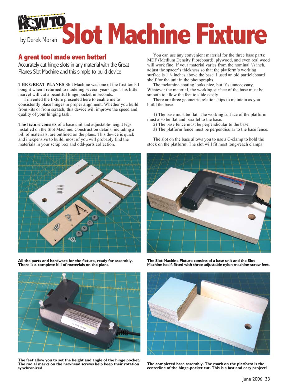
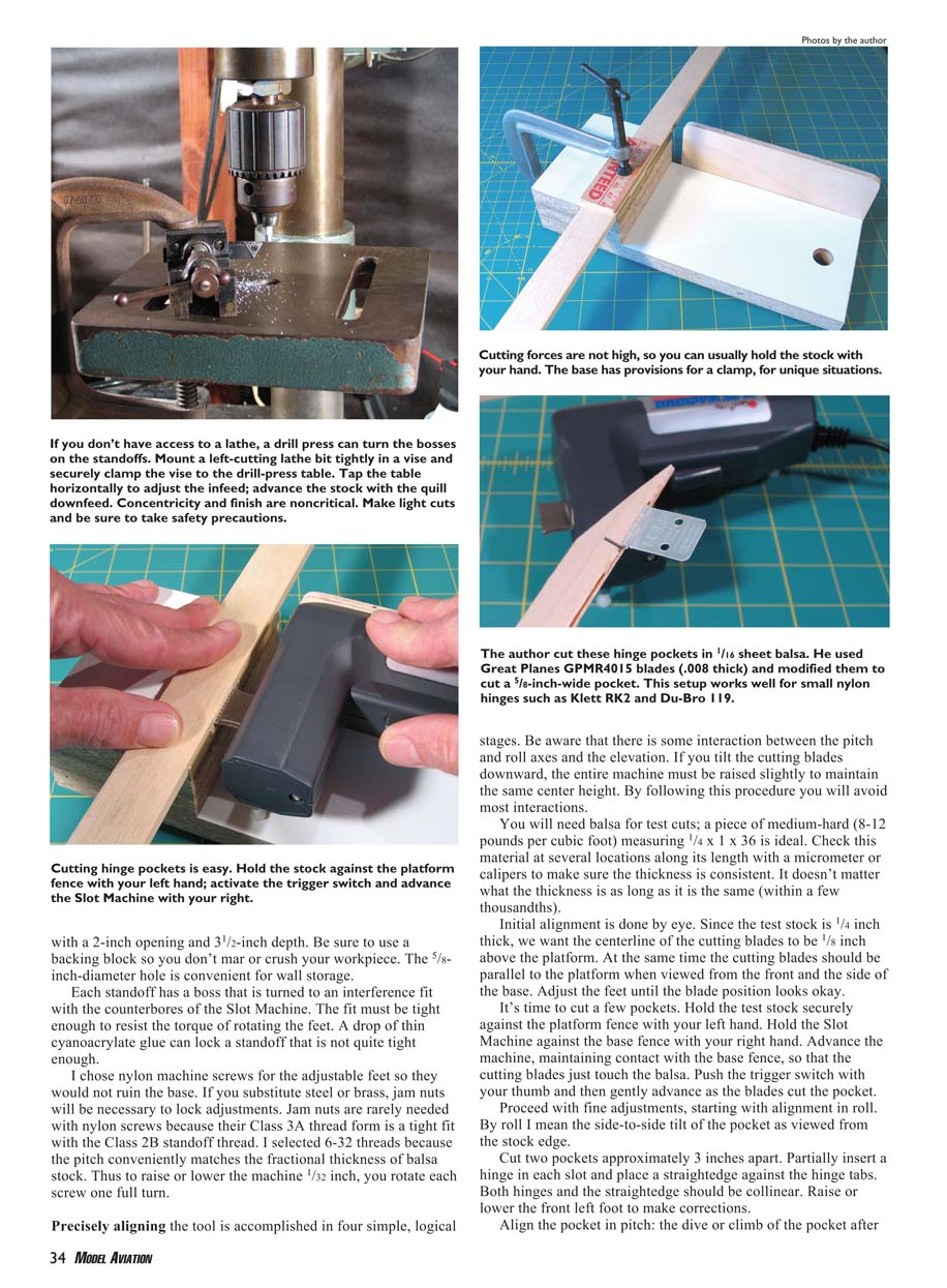
The fixture consists of a base unit and adjustable-height legs installed on the Slot Machine. Construction details, including a bill of materials, are outlined on the plans. This device is quick and inexpensive to build; most of you will probably find the materials in your scrap box and odd-parts collection.
You can use any convenient material for the three base parts; MDF (medium-density fiberboard), plywood, and even real wood will work fine. If your material varies from the nominal 5/8 inch, adjust the spacer’s thickness so that the platform’s working surface is 1 1/4 inches above the base. I used an old particleboard shelf for the unit in the photographs. The melamine coating looks nice, but it’s unnecessary. Whatever the material, the working surface of the base must be smooth to allow the feet to slide easily.
There are three geometric relationships to maintain as you build the base:
- The base must be flat. The working surface of the platform must also be flat and parallel to the base.
- The base fence must be perpendicular to the base.
- The platform fence must be perpendicular to the base fence.
The slot on the base allows you to use a C-clamp to hold the stock on the platform. The slot will fit most long-reach clamps.
The fixture provides a 2-inch opening and 3 1/2-inch depth. Be sure to use a backing block so you don’t mar or crush your workpiece. The 5/8-inch-diameter hole is convenient for wall storage.
Each standoff has a boss that is turned to an interference fit with the counterbores of the Slot Machine. The fit must be tight enough to resist the torque of rotating the feet. A drop of thin cyanoacrylate glue can lock a standoff that is not quite tight enough.
I chose nylon machine screws for the adjustable feet so they would not ruin the base. If you substitute steel or brass, jam nuts will be necessary to lock adjustments. Jam nuts are rarely needed with nylon screws because their Class 3A thread form is a tight fit with the Class 2B standoff thread. I selected 6-32 threads because the pitch conveniently matches the fractional thickness of balsa stock. Thus to raise or lower the machine 1/32 inch, you rotate each screw one full turn.
Alignment procedure
Precisely aligning the tool is accomplished in four simple, logical stages. Be aware that there is some interaction between the pitch and roll axes and the elevation. If you tilt the cutting blades downward, the entire machine must be raised slightly to maintain the same center height. By following this procedure you will avoid most interactions.
You will need balsa for test cuts; a piece of medium-hard (8–12 lb/ft³) measuring 1/4 x 1 x 36 inches is ideal. Check this material at several locations along its length with a micrometer or calipers to make sure the thickness is consistent. It doesn’t matter what the thickness is as long as it is the same (within a few thousandths).
Initial alignment is done by eye. Since the test stock is 1/4 inch thick, we want the centerline of the cutting blades to be 1/8 inch above the platform. At the same time the cutting blades should be parallel to the platform when viewed from the front and the side of the base. Adjust the feet until the blade position looks okay.
It's time to cut a few pockets. Hold the test stock securely against the platform fence with your left hand. Hold the Slot Machine against the base fence with your right hand. Advance the machine, maintaining contact with the base fence, so that the cutting blades just touch the balsa. Push the trigger switch with your thumb and then gently advance as the blades cut the pocket.
Proceed with fine adjustments, starting with alignment in roll. By roll I mean the side-to-side tilt of the pocket as viewed from the stock edge.
- Cut two pockets approximately 3 inches apart.
- Partially insert a hinge in each slot and place a straightedge against the hinge tabs. Both hinges and the straightedge should be colinear.
- Raise or lower the front left foot to make corrections.
Align the pocket in pitch: the drive or climb of the pocket after the blades cut it. Use the same method as roll, but the straightedge is placed on the platform face and the hinge tabs are checked from the side. Raise or lower the back foot to correct pitch.
Alternate pitch check (high-sensitivity method): Cut a new pocket and then insert a long strip of credit-card plastic that is the same width as a hinge. Sight this from the side; any error in pitch will be magnified by the length of the strip and can be easily seen. Raise or lower the rear foot to make corrections.
Align the elevation: the center height of the pocket relative to the workpiece. If the centerline is too high or too low, adjust all three feet equally to raise or lower the Slot Machine. Make small adjustments and recut until the centerline is at the desired position.
Center the pocket’s elevation on the stock edge: cut a pocket and then flip the stock top to bottom. Advance the machine’s cutting blades to the slot and inspect it closely. If the pocket is above the blades, raise the machine half the distance. If the pocket is below the blades, lower the machine half the distance. Raise and lower by turning all three feet an equal amount. The pocket is centered when the cutting blades will enter it without rubbing on the top or bottom surfaces.
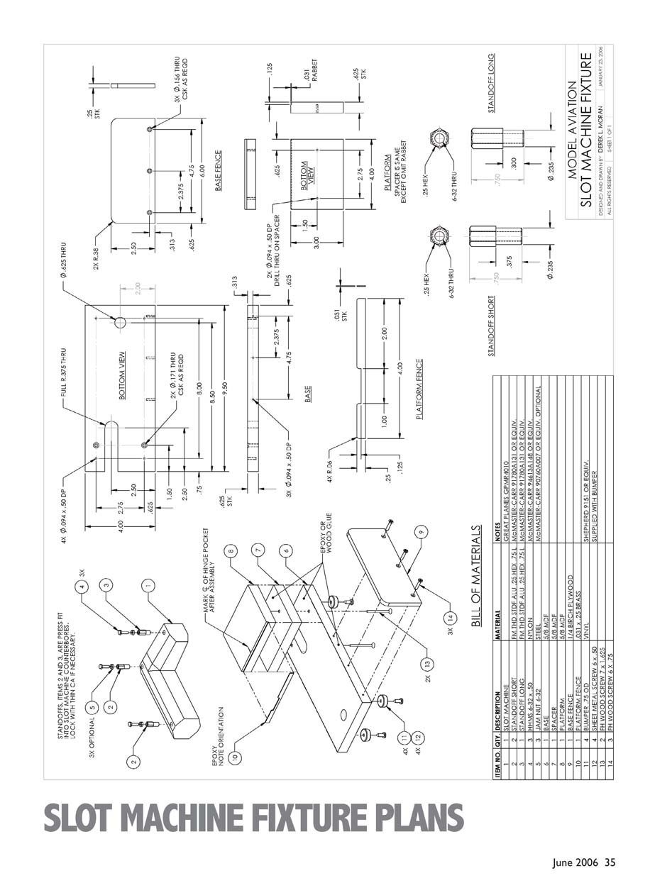
Once the machine is aligned, add index marks to the feet to help keep their rotation synchronized. Make marks with a fine-point Sharpie pen, drawing a radial line that is parallel to the direction of the cut.
At this point you can adapt to different standard stock thicknesses by counting turns of the feet. If the machine is adjusted for 1/4-inch stock and you want to cut pockets in 3/8-inch stock, unscrew (raise) all three feet exactly two turns. However, don’t blindly rely on this feature because balsa stock often varies from its nominal thickness. Always verify your adjustment by flipping the stock top to bottom as described above.
Mark the platform to indicate the centerline of the cut. Use this mark to locate the stock when cutting pockets for your model.
- Clamp a piece of stock to the platform, against the fence, and cut a pocket.
- With the stock still clamped to the platform, place a mark on the fence directly below the pocket centerline.
- Remove the stock and extend the mark along the platform and spacer using a square. Use the Sharpie as before.
When the pockets are properly located and aligned, cut the production parts. Use a backing block so you don't mar or crush your workpiece, and use the base's clamping slot for long or awkward pieces.
SLOT MACHINE FIXTURE PLANS
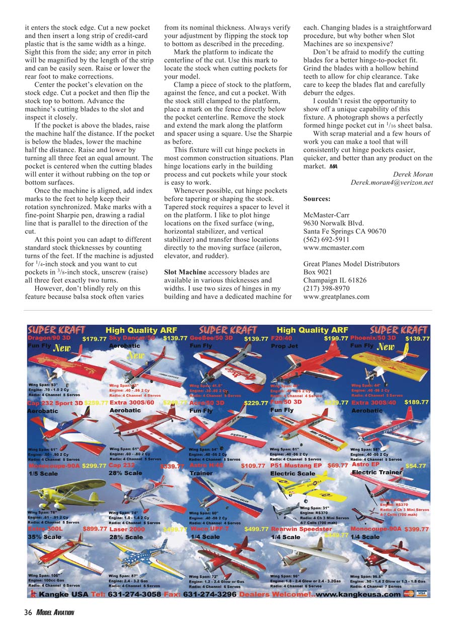
#### Bill of Materials
ITEM NO. QTY. DESCRIPTION MATERIALS
(See plans for detailed parts list and dimensions.)
Tips and additional notes
- This fixture will cut hinge pockets in most common construction situations. Plan hinge locations early in the building process and cut pockets while your stock is easy to work.
- Whenever possible, cut hinge pockets before tapering or shaping the stock. Tapered stock requires a spacer to level it on the platform. I like to plot hinge locations on the fixed surface (wing, horizontal stabilizer, and vertical stabilizer) and transfer those locations directly to the moving surface (aileron, elevator, and rudder).
- Slot Machine accessory blades are available in various thicknesses and widths. I use two sizes of hinges in my building and have a dedicated machine for each. Changing blades is a straightforward procedure, but why bother when Slot Machines are so inexpensive?
- Don’t be afraid to modify the cutting blades for a better hinge-to-pocket fit. Grind the blades with a hollow behind the tooth to allow for chip clearance. Take care to keep the blades flat and carefully deburr the edges.
With scrap material and a few hours of work you can make a tool that will consistently cut hinge pockets easier, quicker, and better than any product on the market.
Derek Moran [email protected]
Sources
- McMaster-Carr
9630 Norwalk Blvd. Santa Fe Springs, CA 90670 (562) 692-5911 www.mcmaster.com
- Great Planes Model Distributors
Box 9021 Champaign, IL 61826 (217) 398-8970 www.greatplanes.com
Transcribed from original scans by AI. Minor OCR errors may remain.

