
Small-Field Flying
Paul Bradley 32238 Spinnaker Run, Magnolia TX 77354 E-mail: [email protected]
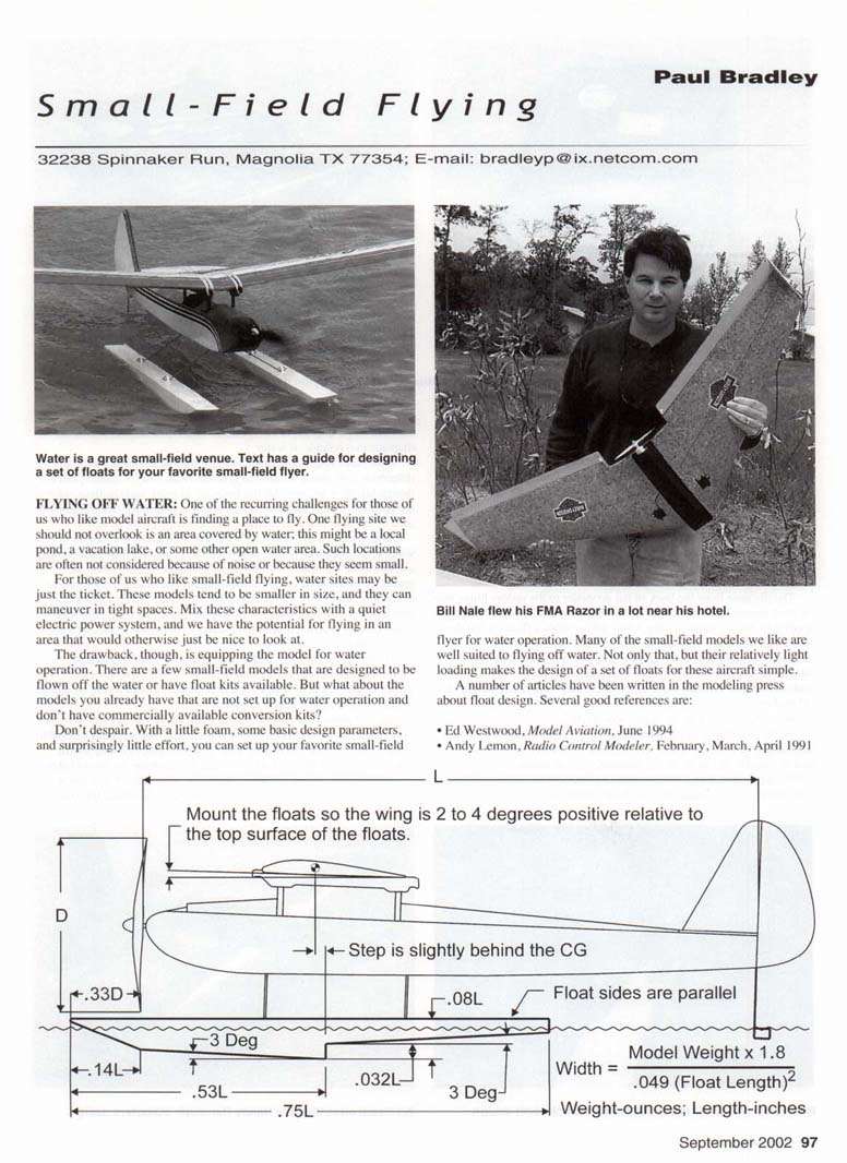
FLYING OFF WATER: One of the recurring challenges for those of us who like model aircraft is finding a place to fly. One flying site we should not overlook is an area covered by water; this might be a local pond, a vacation lake, or some other open water area. Such locations are often not considered because of noise or because they seem small.
For those of us who like small-field flying, water sites may be just the ticket. These models tend to be smaller in size, and they can maneuver in tight spaces. Mix these characteristics with a quiet electric power system, and we have the potential for flying in an area that would otherwise just be nice to look at.
The drawback, though, is equipping the model for water operation. There are a few small-field models that are designed to be flown off the water or have float kits available. But what about the models you already have that are not set up for water operation and don't have commercially available conversion kits?
Don't despair. With a little foam, some basic design parameters, and surprisingly little effort, you can set up your favorite small-field flyer for water operation. Many of the small-field models we like are well suited to flying off water. Not only that, but their relatively light loading makes the design of a set of floats for these aircraft simple.
A number of articles have been written in the modeling press about float design. Several good references are:
- Ed Westwood, Model Aviation, June 1994
- Andy Lemon, Radio Control Modeler, February, March, April 1991
- Chuck Cunningham, Radio Control Modeler, July 1991, September 1994, October 1997
Of those references, the material Chuck Cunningham presented seems to be best suited to the small-field flyer. Following his straightforward layout guide, you can put together a nice set of simple-geometry floats that work great. Let's take a look at Chuck's design approach.
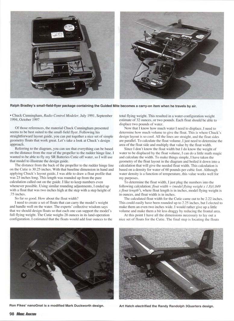
Referring to the diagram, you can see that everything can be based on the distance from the rear of the propeller to the rudder hinge line. I wanted to be able to fly my SR Batteries Cutie off water, so I will use that model to illustrate the design guide.
The distance from the back of the propeller to the rudder hinge line on the Cutie is 30.25 inches. With that baseline dimension in hand and applying Chuck's layout guide, I was able to draw a float profile that was 23 inches long. This length was rounded up from the pure calculation called out on the guide. I like to keep numbers even whenever possible. Using similar rounding adjustments, I ended up with a float that was two inches high at the step, with a step height of 0.75 inches.
How about the float width? I need to create a set of floats that can carry the model's weight and handle well on the water. The experts' collective wisdom says that we should design floats so that each one can support the model's full flying weight. The Cutie weighs 28 ounces in its land-operation configuration. I estimated that the floats would add four ounces to the total flying weight. This resulted in a water-configuration weight estimate of 32 ounces, or two pounds. Each float should be able to displace two pounds of water.
Now that I know how much water I need to displace, I need to determine how much volume to give the float. This is where Chuck's design layout is so cool. All the lines are straight, and the float sides are parallel. To calculate the float volume, I just need to determine the area of the front face of the float and multiply that value by the float width.
Since I don't know the float width but I do know the weight of water to be displaced by the float volume, I can do a little math magic and calculate the width. To make things simple, I have taken the geometry of the float layout in the diagram and boiled it down into a calculation that will give the needed float width. This calculation is based on a density for water of 60 pounds per cubic foot. Although water density is a function of temperature, this value works well for my purposes.
To determine the float width, I just plug the numbers into the following calculation: float width = (model flying weight x 1.8) / (0.049 x float length^2) where float length is in inches, model flying weight is in ounces, and float width is in inches.
The calculated float width for the Cutie came out to be 2.22 inches. This could easily have been rounded up to 2.25 inches, but I elected to make them an even two inches wide. I would rather give up a little volume and make them a bit less draggy by reducing the frontal area.
At this point I have all the dimensions necessary to lay out a nice set of floats for the Cutie. The final step is locating the floats on the model, and there are three parameters I want to consider.
- The float tips should be roughly one propeller diameter ahead of the propeller.
- The float step should be located just behind the model's center of gravity. You may need to make some minor adjustments to your float design to accommodate these two parameters.
- The floats should be mounted so that the model's wing will maintain a positive angle of attack as the model moves along the water surface. A value in the 2° to 4° range seems to give the best results.
With these guidelines in hand, you should be able to develop a successful set of floats for your small-field model. A photo shows the results on the Cutie. I used built-up balsa construction in keeping with the overall look and feel of the model. The completed floats did, in fact, weigh in at four ounces.
Foam construction would have been nearly equal in weight, or even a bit lighter. The straight lines of this float layout also make foam-based floats quite a bit quicker to build. Almost all you need is a hard back on the top of each float to give some stiffness and anchor the struts. Something like a strip of 1/4 x 1/2-inch spruce epoxied to the foam would do nicely. For models smaller than the Cutie, foam would be the ideal material choice.
One other thing regarding flying off water is controlling the model while it is moving on the water; this is commonly handled by a water rudder. Depending on the nature of your water site, it is often necessary to taxi out to a takeoff area, then taxi back to your position after landing. When the model is up to speed and on step, the air rudder can handle the maneuvering demands.
At taxiing speeds, especially if there is a crosswind, the air rudder will be ineffective. The easiest way to handle this problem is to add a water rudder to your air rudder. For our size models, this is much easier than adding rudders to the floats that, in turn, need a mechanical linkage to drive them.
You don't need much area for the water rudder—just enough to allow you to steer the model on the water. Too much area can lead to overcontrol problems as the model gains speed. For the Cutie, a water rudder that is 1/2 x 1 inch was used. It turned out just right. The floats built for the Cutie work great, and the model handles their presence with no problem.
If you have a suitable body of water near you, why not add that area to your list of favorite small-field-flying sites?
The Traveling Small-Field Flyer
One of the great things about flying on small fields is that our models tend to be on the smaller side. This can be a great advantage if we do much traveling; smaller models can often be taken along so that we can have flying enjoyment at our destination. This is especially true for the regular business traveler.
Bill Nale, who is from the area around Austin, Texas, found himself on an extended work assignment during the early part of this year. Lo and behold, there was a nice, empty lot next to his hotel parking area. He immediately saw an opportunity to while away the normally long off-hours by doing some small-field flying.
During one of his trips home, Bill packed several suitable models for the venue. The rest of his time during this work assignment was much more enjoyable because he was able to get in plenty of small-field flying.
Bill had the advantage of traveling by car. This makes it much easier to take some favorite small-field models. What about the times we must travel by air? There are take-along options for this situation as well. Many models can easily be set up to break down into a fairly small package. When placed in a suitable container, the model and its support gear can be carried on-item.
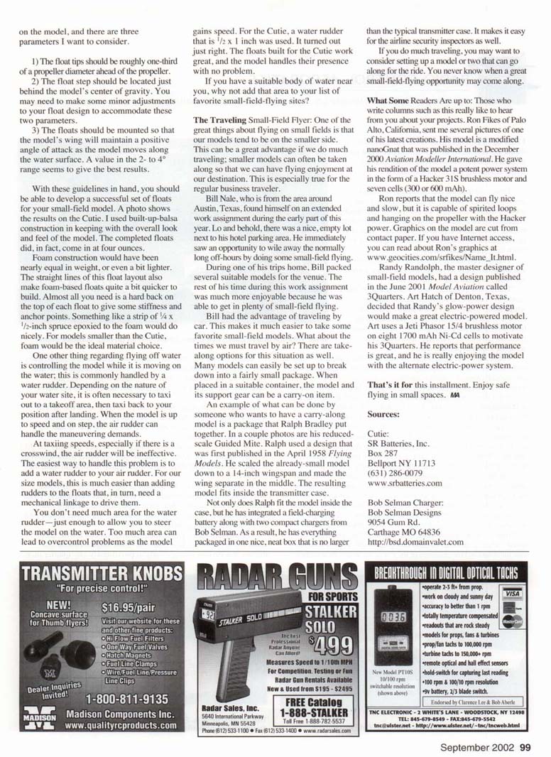
An example of what can be done by someone who wants to have a carry-along model is a package that Ralph Bradley put together. In a couple photos he is reduced-to-scale Guided Mite. Ralph used a design that was first published in the April 1958 Flying Models. He scaled the already-small model down to a 14-inch wingspan and made the wing separate in the middle. The resulting model fits inside the transmitter case.
Not only does Ralph fit the model inside the case, but he has integrated a field-charging battery along with two compact chargers from Bob Selman. As a result, he has everything packaged in one nice, neat box that is no larger than the typical transmitter case. It makes it easy for the airline security inspectors as well.
If you do much traveling, you may want to consider setting up a model or two that can go along for the ride. You never know when a great small-field-flying opportunity may come along.
What Some Readers Are Up To
Those who write columns such as this really like to hear from you about your projects. Ron Fikes of Palo Alto, California, sent me several pictures of one of his latest creations. His model is a modified nanoGnat that was published in the December 2000 Aviation Modeller International. He gave this rendition of the model a potent power system in the form of a Hacker 315 brushless motor and seven cells (300 or 600 mAh).
Ron reports that the model can fly nice and slow, but it is capable of spirited loops and hanging on the propeller with the Hacker power. Graphics on the model are cut from contact paper. If you have Internet access, you can read about Ron's graphics at www.geocities.com/ronfikes/Name_It.html.
Randy Randolph, the master designer of small-field models, had a design published in the June 2001 Model Aviation called 3Quarters. Art Hatch of Denton, Texas, described that Randy's glow-powered design would make a great electric-powered model. Art uses a JetI Phasor 15/4 brushless motor on eight 1700 mAh Ni-Cd cells to power his 3Quarters. He reports that performance is great, and he is really enjoying the model with the alternate electric-power system.
That's it for this installment. Enjoy safe flying in small spaces.
Sources
Cutie: SR Batteries, Inc. Box 287 Bellport NY 11713 (631) 286-0079 www.srbatteries.com
Bob Selman Charger: Bob Selman Designs 9054 Gum Rd. Carthage MO 64836 http://bsd.domainvalet.com
Transcribed from original scans by AI. Minor OCR errors may remain.

