
Small-Field Flying
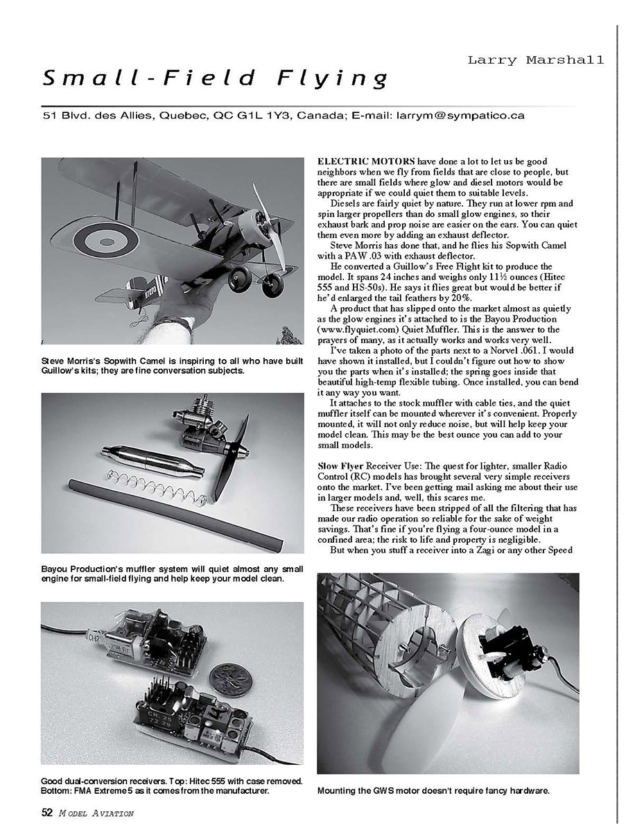
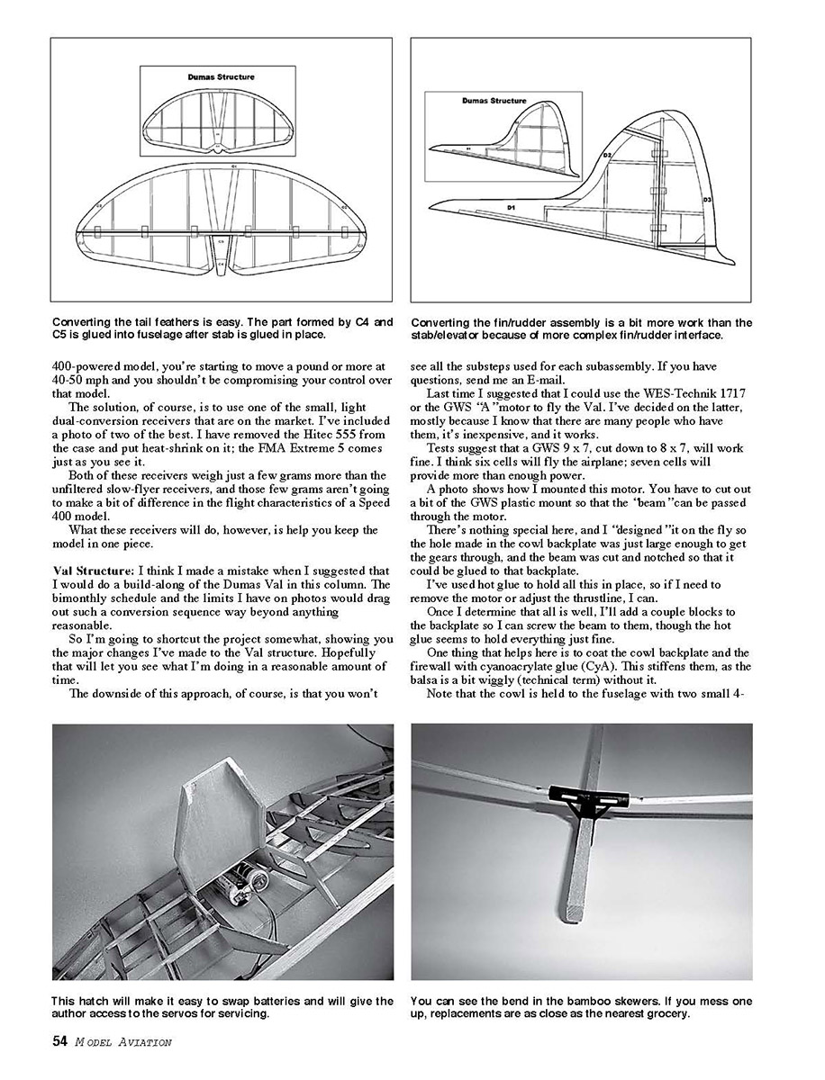
Converting the tail feathers is easy. The part formed by C4 and C5 is glued into the fuselage after the stab is glued in place.
If you are flying a Speed 400-powered model, you're starting to move a pound or more at 40–50 mph and you shouldn't be compromising your control over that model.
The solution, of course, is to use one of the small, light dual-conversion receivers that are on the market. I've included a photo of two of the best. I have removed the Hitec 555 from the case and put heat-shrink on it; the FMA Extreme 5 comes just as you see it.
Both of these receivers weigh just a few grams more than the unfiltered two-flyer receivers, and those few grams aren't going to make a bit of difference in the flight characteristics of a Speed 400 model.
What these receivers will do, however, is help you keep the model in one piece.
Val Structure
I think I made a mistake when I suggested that I would do a build-along of the Dumas Val in this column. The bimonthly schedule and the limits I have on photos would drag out such a conversion sequence way beyond anything reasonable.
So I'm going to shortcut the project somewhat, showing you the major changes I've made to the Val structure. Hopefully that will let you see what I'm doing in a reasonable amount of time.
The downside of this approach, of course, is that you won't see all the substeps used for each subassembly. If you have questions, send me an E-mail.
Motor choice
Last time I suggested that I could use the WES-Technik 1717 or the GWS "A" motor to fly the Val. I've decided on the latter, mostly because I know that there are many people who have them, it's inexpensive, and it works.
Tests suggest that a GWS 9 x 7, cut down to 8 x 7, will work fine. I think six cells will fly the airplane; seven cells will provide more than enough power.
Mounting the motor
A photo shows how I mounted this motor. You have to cut out a bit of the GWS plastic mount so that the "beam" can be passed through the motor.
There's nothing special here, and I "designed" it on the fly so the hole made in the cowl backplate was just large enough to get the gears through, and the beam was cut and notched so that it could be glued to that backplate.
I've used hot glue to hold all this in place, so if I need to remove the motor or adjust the thrustline, I can.
Once I determine that all is well, I'll add a couple blocks to the backplate so I can screw the beam to them, though the hot glue seems to hold everything just fine.
One thing that helps here is to coat the cowl backplate and the firewall with cyanoacrylate glue (CyA). This stiffens them, as the balsa is a bit wiggly (technical term) without it.
Note that the cowl is held to the fuselage with two small 4-40 screws. I simply glued bolts to the back of the firewall after drilling two holes straight through from the cowl front.
One of the nice things about these low-power systems is that simple methods are sufficient to hold things in place.
Tail feathers and control horns
Obviously I've got to make the tail feathers move. I've provided a couple drawings to show you how I modified the structure.
There are other ways of doing this, of course, but I wanted to use as many of the laser-cut parts as possible. In fact, I built the parts according to the plan, except for putting an extra set of stringers at the hinge line.
Thus, I just cut through the "outline" parts when I was ready to separate the fin/rudder and stabilizer/elevator parts. I think the drawings are self-explanatory.
I'll use a couple of Tim McDonough's laser-cut control horns (www.tim.mcdonough.net). You cut the slots for these before covering, and install them with a bit of CyA after you cover the parts.
One-piece wing, hatch, and radio installation
I've decided to build this model as a one-piece affair. I'm too lazy to assemble small models when I go flying, so the wing will be glued to the fuselage.
I also want to be able to swap batteries easily, so I've built a hinged hatch in the bottom of the wing and a simple platform for the battery to sit on. A photo is worth a thousand words. It's a simple affair that will have a hinge on one end and a simple pin latch on the other.
I'll be using a simple platform to hold the HS-50 servos and the receiver. I haven't finished this installation yet, but I believe I'll access them through the hatch I just described.
Next time I'll show you the completed model with hardware installed and discuss covering.
Lite Stik Dihedral
Lite Stiks are really popular, but one problem with them is well acknowledged: they need more dihedral.
The most common way to provide it is to tie the wingtips together, pulling them upward. This not only looks silly, it adds a draggy wire. There's gotta be a better way.
The wing mounts are made from bamboo barbecue skewers, and those of you who have flown Free Flight know that bamboo can be bent by the application of heat.
So why not just bend the mounts to increase the dihedral? I used a soldering iron and did just that.
Mark the place where the mount exits the plastic part, then apply heat to this area. Pull it down over a somewhat sharp corner (I used the edge of a file cabinet). For good measure, I coated the bend with thin CyA.
I've got 30–40 flights on my Lite Stik, and it works just fine. (See photo.) MA
Transcribed from original scans by AI. Minor OCR errors may remain.

