
SoarCerer - 2008/03
by Jean "JG" Pailet
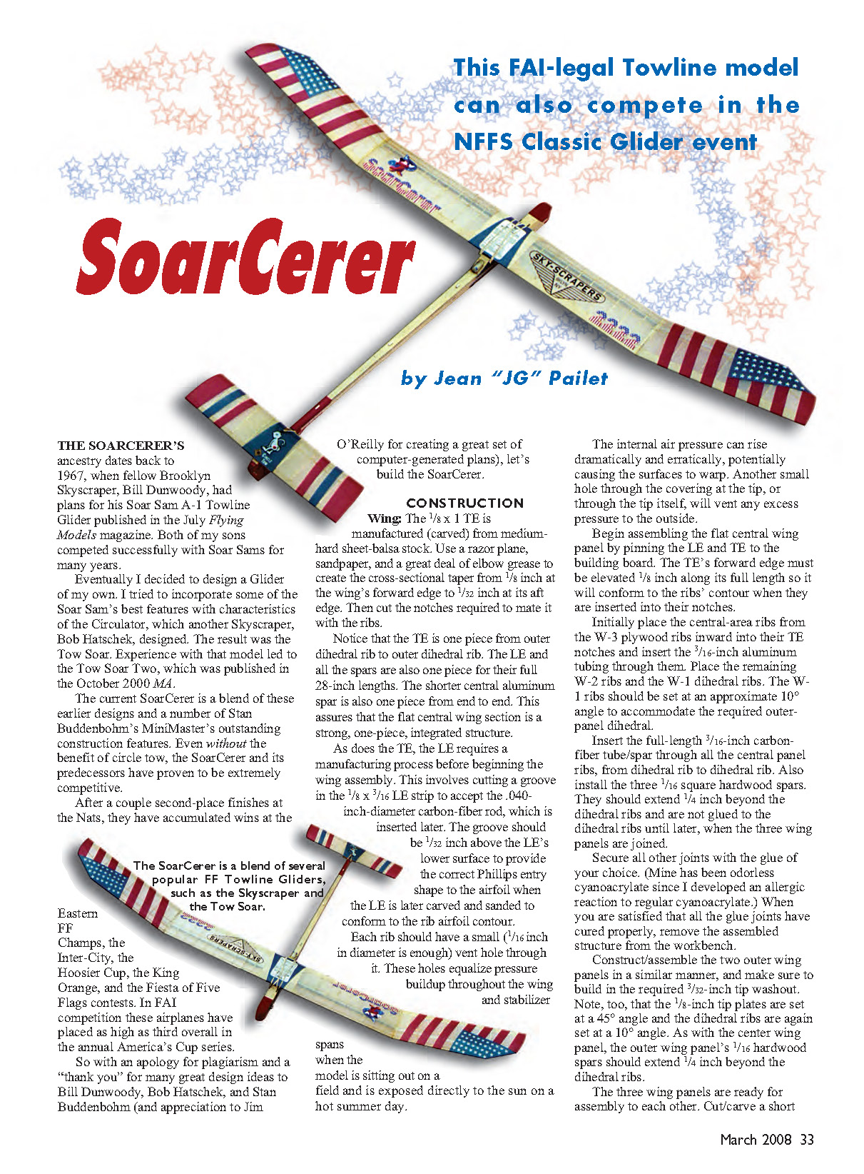
The SoarCerer’s ancestry dates back to 1967, when fellow Brooklyn Skyscraper Bill Dunwoody had plans for his Soar Sam A-1 Towline Glider published in the July Flying Models magazine. Both of my sons competed successfully with Soar Sams for many years.
Eventually I decided to design a glider of my own. I tried to incorporate some of the Soar Sam’s best features with characteristics of the Circulator, which another Skyscraper, Bob Hatschek, designed. The result was the Tow Soar. Experience with that model led to the Tow Soar Two, which was published in the October 2000 Model Aviation.
The current SoarCerer is a blend of these earlier designs and a number of Stan Buddenbohm’s MiniMaster’s outstanding construction features. Even without the benefit of circle tow, the SoarCerer and its predecessors have proven to be extremely competitive.
After a couple of second-place finishes at the Nats, they have accumulated wins at the Eastern FF Champs, the Inter-City, the Hoosier Cup, the King Orange, and the Fiesta of Five Flags contests. In FAI competition these airplanes have placed as high as third overall in the annual America’s Cup series.
So, with an apology for plagiarism and a “thank you” for many great design ideas to Bill Dunwoody, Bob Hatschek, and Stan Buddenbohm (and appreciation to Jim O’Reilly for creating a great set of computer-generated plans), let’s build the SoarCerer.
CONSTRUCTION
Wing
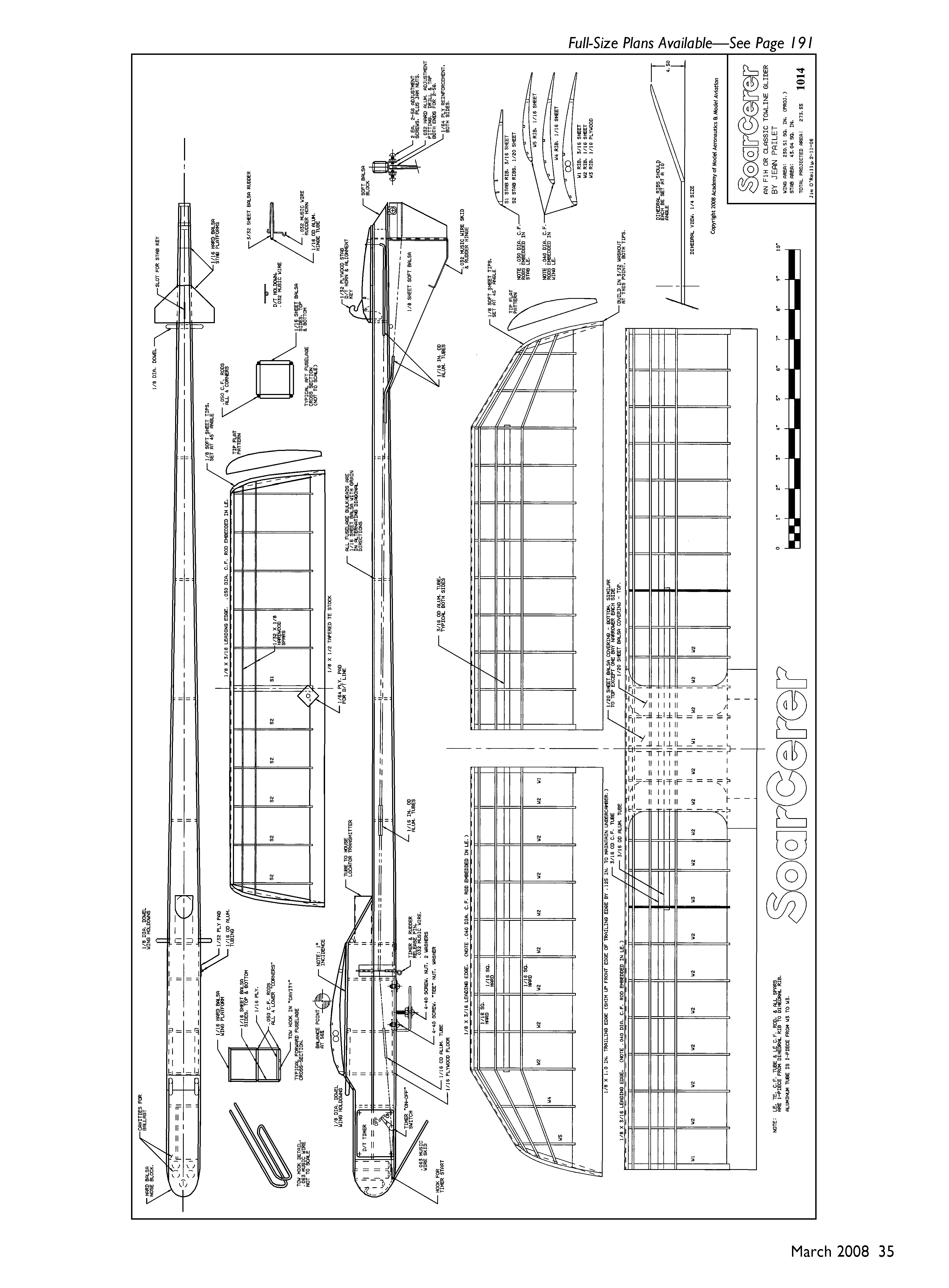
The 1/8 x 1-inch TE is manufactured (carved) from medium-hard sheet-balsa stock. Use a razor plane, sandpaper, and a great deal of elbow grease to create the cross-sectional taper from 1/8 inch at the wing’s forward edge to 1/32 inch at its aft edge. Then cut the notches required to mate it with the ribs.
Notice that the TE is one piece from outer dihedral rib to outer dihedral rib. The LE and all the spars are also one piece for their full 28-inch lengths. The shorter central aluminum spar is one piece from end to end. This assures that the flat central wing section is a strong, one-piece, integrated structure.
As does the TE, the LE requires a manufacturing process before beginning the wing assembly. This involves cutting a groove in the 1/8 x 3/16-inch LE strip to accept the 0.040-inch-diameter carbon-fiber rod, which is inserted later. The groove should be 1/32 inch above the LE’s lower surface to provide the correct entry shape to the airfoil when the LE is later carved and sanded to conform to the rib airfoil contour.
Each rib should have a small (1/16-inch-diameter is enough) vent hole through it. These holes equalize pressure buildup throughout the wing and stabilizer spans when the model is sitting out on a field and is exposed directly to the sun on a hot summer day. Internal air pressure can rise dramatically and erratically, potentially causing the surfaces to warp. Another small hole through the covering at the tip, or through the tip itself, will vent any excess pressure to the outside.
Begin assembling the flat central wing panel by pinning the LE and TE to the building board. The TE’s forward edge must be elevated 1/8 inch along its full length so it will conform to the ribs’ contour when they are inserted into their notches.
Initially place the central-area ribs from the W-3 plywood ribs inward into their TE notches and insert the 3/16-inch aluminum tubing through them. Place the remaining W-2 ribs and the W-1 dihedral ribs. The W-1 ribs should be set at an approximate 10° angle to accommodate the required outer-panel dihedral.
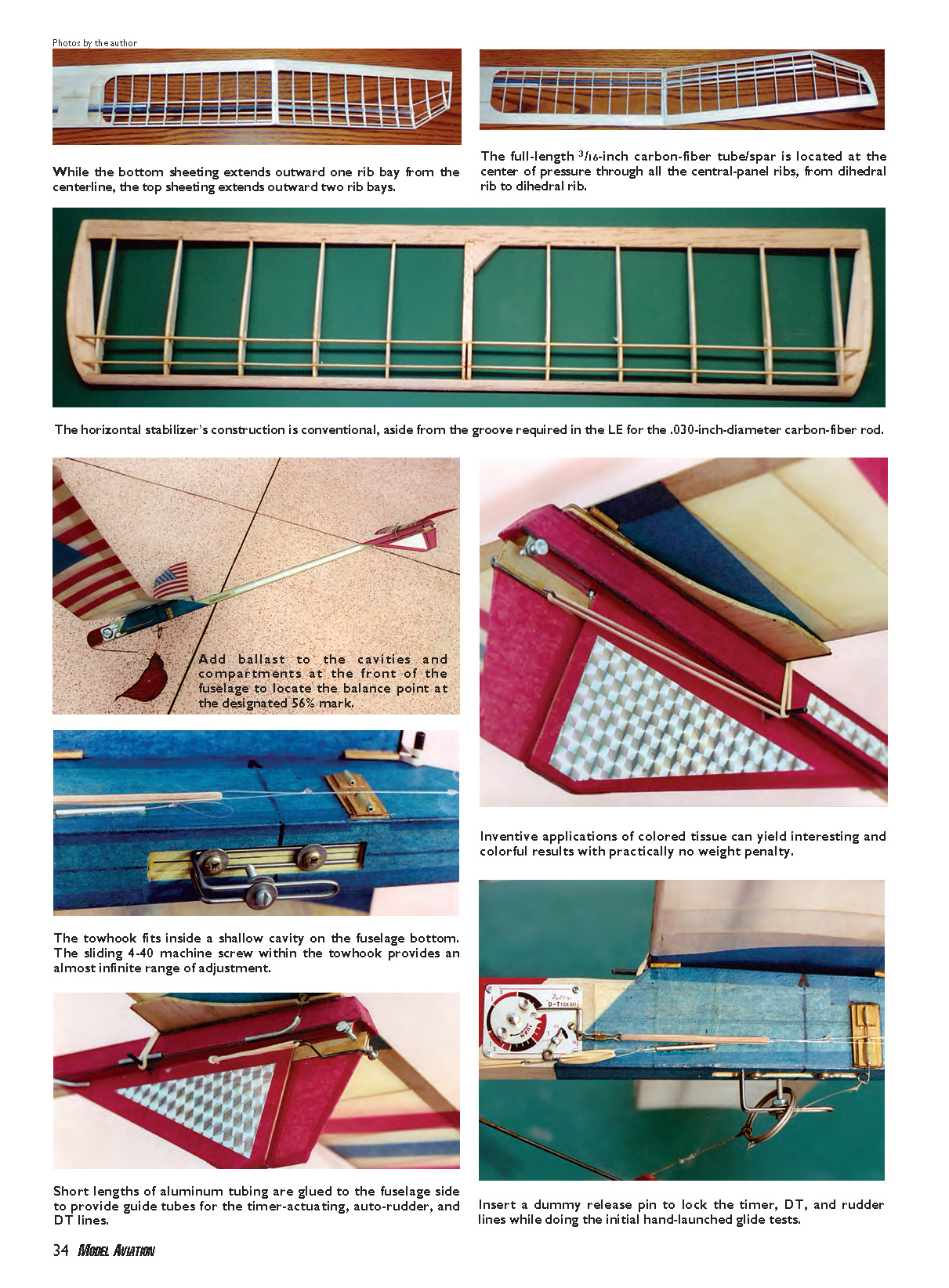
Insert the full-length 3/16-inch carbon-fiber tube/spar through all the central panel ribs, from dihedral rib to dihedral rib. Also install the three 1/16-inch square hardwood spars. They should extend 1/4 inch beyond the dihedral ribs and are not glued to the dihedral ribs until later, when the three wing panels are joined.
Secure all other joints with the glue of your choice. (Mine has been odorless cyanoacrylate since I developed an allergic reaction to regular cyanoacrylate.) When you are satisfied that all the glue joints have cured properly, remove the assembled structure from the workbench.
Construct and assemble the two outer wing panels in a similar manner, and make sure to build in the required 3/32-inch tip washout. Note, too, that the 1/8-inch tip plates are set at a 45° angle and the dihedral ribs are again set at a 10° angle. As with the center wing panel, the outer wing panel’s 1/16-inch hardwood spars should extend 1/4 inch beyond the dihedral ribs.
The three wing panels are ready for assembly to each other. Cut/carve a short length of hardwood dowel to form a dihedral brace within the carbon-fiber and aluminum main spars where they mate at the dihedral joint. Cut mating angles on the 1/4-inch overhang of the three hardwood spars so they will form a lap joint where they meet at the dihedral ribs.
Secure the internal dowel dihedral brace to the inside of the respective carbon-fiber and aluminum spars with a slow-drying epoxy glue (I use 3M Scotch-Weld product DP460). Similarly, use a slow-drying epoxy on the dihedral ribs’ mating faces. This will allow you time to tack-glue the other dihedral joints (ribs, spars, LE, and TE) as you set the proper alignment and dihedral angle.
After the three wing panels are assembled to each other, glue the 0.040-inch carbon-fiber rods into the grooves in their respective LEs. Carve and sand the LEs to provide the desired airfoil contour. The final step in the wing construction is installing the center-area 1/20-inch balsa sheeting over and under the LE, TE, and ribs.
Although the bottom sheeting extends outward one rib bay from the centerline, the top sheeting extends outward two rib bays. Some final carving and sanding will properly contour the sheeting where it overlaps the LE.
Horizontal Stabilizer
This component’s construction is conventional, aside from the groove required in the LE for the 0.030-inch-diameter carbon-fiber rod. You must cut a slot in the forward part of the 3/16-inch center rib to accept the 1/32-inch plywood DT horn/alignment key.
After assembling the LE, TE, ribs, and spars, insert the carbon-fiber rod into the LE. Carve and sand the LE to the appropriate airfoil shape in conformance with the rib contours.
Fin/Vertical Tail and Rudder
The fin and rudder are simple sheet-balsa flat surfaces. The fin LE is sanded to a rounded cross-section, and the aft portion of the rudder is tapered to a 1/32-inch TE thickness.
Since the grain of these surfaces is vertical, I add a small piece of 1/64-inch plywood to each side of the upper portion of the rudder to provide stiffness and a bearing surface for the rudder angle-adjustment screws. The actual rudder-adjusting mechanism can be homemade or purchased from FAI Model Supply.
The rudder hinge is a length of 1/16-inch-outside-diameter aluminum tubing glued to the forward edge of the rudder and a length of 1/32-inch-diameter music wire bent to form the hinge and tail skid. The wire should extend up into the fuselage. The auto-rudder actuating horn is bent from 1/32-inch music wire.
Fuselage
The lower portion of the fuselage, from nose to tail, is essentially a sheet-balsa box with 0.050-inch-diameter carbon-fiber rods laid into each corner. The upper forward fuselage is a balsa box forming the wing mount. The fuselage top, bottom, and sides are cut from 1/16-inch sheet balsa, as are all formers.
I recommend that the formers for the lower fuselage box have a grain that is diagonal in alternating directions. Before assembling the box, glue a 1/16-inch plywood towhook attachment floor with 4-40 T-nuts installed to the inside of the fuselage bottom. All four corners of the lower fuselage box are open to allow for installing the corner carbon-fiber rods once the basic balsa box has been constructed.
Build the upper forward fuselage/wing mount onto the lower fuselage box. This wing mount/platform should provide 1° positive wing-incidence angle, and its hard-balsa upper surface’s grain must be crossways (at 90°) to the fuselage centerline.
A balsa block forms the nose of the fuselage, and a smaller balsa block fills in the aft end of the fuselage. Holes drilled into the nose block will provide cavities for ballast when performing final balancing. Installing a false wall behind the timer, in the timer bay, will provide an additional area for ballast if required.
The 1/8-inch hard-balsa stabilizer platform, with a slot to accept the stabilizer key, is installed on the aft fuselage, as is a 1/16-inch pad at the stabilizer TE. Hardwood dowels that are 1/8 inch in diameter provide tie-downs for the wing and stabilizer.
The towhook and nose skid are formed from 1/16-inch music wire. The timer/rudder release pin and the stabilizer DT hold-down are made from 1/32-inch music wire. The release pin slides into two short lengths of 1/16-inch-diameter aluminum tubing glued to a 1/32-inch plywood pad, which, in turn, is glued to the fuselage side.
Attaching the towhook to the fuselage within a shallow cavity on the fuselage bottom and the sliding 4-40 machine screw within the towhook provide an almost infinite range of adjustment for the proper positioning of the towline to accommodate varying balance, trim, and wind conditions.
Cut an opening for the DT timer into the fuselage side. Short lengths of aluminum tubing are glued to the fuselage side to provide guide tubes for the timer-actuating, auto-rudder, and DT lines. The accompanying photos, coupled with the plans, will provide clear insight into how to rig the required lines and rubber bands.
A short length of light plastic or cardboard tubing installed just aft of the wing provides a housing for a locator transmitter (and I strongly urge you not to fly without one).
Covering and Finishing
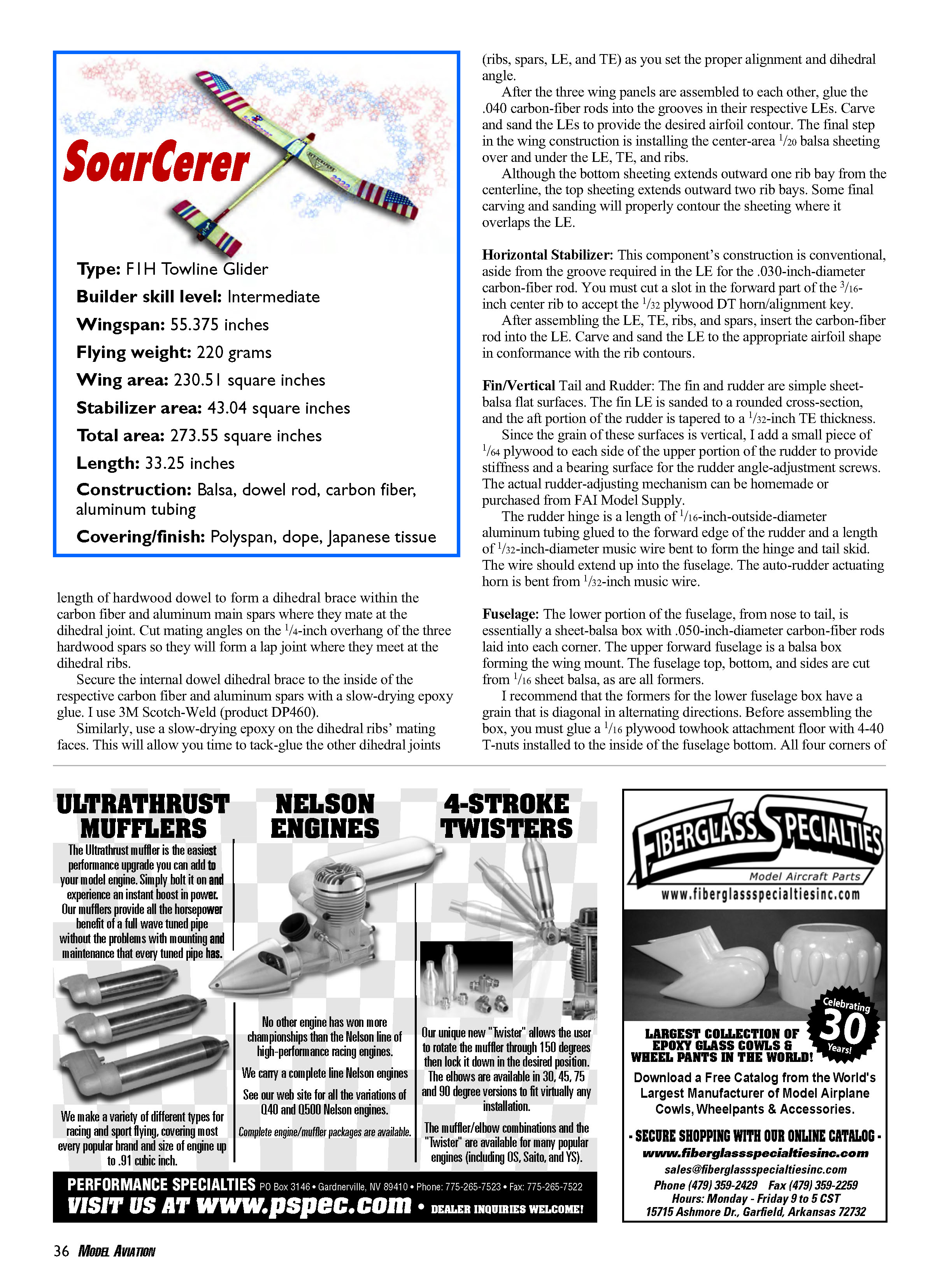
Polyspan is the only covering material I use on wing and tail surfaces. It provides all the best characteristics of Japanese tissue (particularly enhancing a structure’s torsional rigidity) for a small weight penalty.
Most importantly, Polyspan is durable and puncture-resistant. In addition, unwanted warps can be removed and desired trim adjustments can be made with a heat gun; the surface retains the set you want.
Polyspan’s only shortcoming is that it comes in only one not-so-vivid color: washed-out white. The accompanying photos illustrate inventive applications of colored tissue (at effectively no weight penalty) that can yield interesting and colorful results.
All surfaces to which Polyspan will be adhered must be given at least two coats of clear dope, thinned 50%, with a light sanding after each coat. I prefer to use nitrate dope since there is no need to worry about fuel-proofing on a nonpowered model such as this.
Apply a third coat of unthinned dope to the underside of all the ribs. This will help assure that the covering will adhere properly to the significant undercamber when heat-shrunk later.
Apply/glue the Polyspan to the respective surfaces with either thinner or heavily diluted dope. A hot (approximately 300°F) covering iron will help bend the Polyspan around any small radii, such as the wing and stabilizer LEs and tips, as it is being applied.
After covering, use a similarly hot iron to remove any wrinkles and tighten the skin over all the surfaces. Apply two coats of 50%-thinned clear nitrate dope to all the surfaces.
Now is the time to get inventive and artistic with colorful trimming. As I mentioned, the simple application, with thinner, of colored Japanese tissue can accomplish wonders in making your model beautiful and, more importantly, visible against the backgrounds of sky and earth.
Apply two more coats of 50%-thinned nitrate dope to all covered and decorated surfaces. Then you can apply any desired decals, logos, and the required AMA license numbers.
I do not use Polyspan on the all-wood surfaces of the fuselage, fin, and rudder. Japanese tissue, in your choice of color(s), will do the job fine.
Give all the exposed wood surfaces two coats of 50%-thinned nitrate dope with the requisite sanding afterward. Then apply the tissue using either thinned dope or only thinner. Finish the job with four coats of the thinned dope.
Final Assembly
Install the nose skid using epoxy cement (3M Scotch-Weld is fine too). Glue the fin to the bottom of the fuselage (Ambroid or cyanoacrylate are okay here as well), making certain that it is aligned perfectly on the fuselage centerline.
Properly align the wing and tail with respect to the fuselage centerline. They must be "square" (at right angles) to the fuselage centerline and retain that relationship every time they are installed.
Short (1/4 to 1/2 inch) lengths of 1/16-inch-diameter dowels, split lengthwise and glued to the undersides of the wing LE and TE and stabilizer TE, will serve this purpose. (The DT horn’s alignment key will do the job at the stabilizer LE.) Positioned on the wing and stabilizer so they rest against the fuselage sides assures the proper alignment.
With the wing, stabilizer, timer, and tracker/transmitter installed, add ballast to the cavities/compartments at the front of the fuselage to locate the balance point at the designated 56% of the wing’s root chord.
Trimming and Testing
If you have a locator/transmitter, install it now.
As shown on the plans, my models have flown best when ballasted to balance at 56% of the wing root chord. Insert a dummy release pin to lock the timer, DT, and rudder lines while doing the initial hand-launched glide tests. These are aimed at achieving a straight-ahead glide path using rudder trim only.
Simultaneously adjust for a flat, no-stall/no-dive glide path by shimming the stabilizer LE or TE as required. Ballasting the nose or tail to shift the CG fore or aft a bit can also be helpful during this two-mode stage of trimming.
During glide-mode trimming, keep the timer locked with the dummy release pin, but release the rudder line. Right-hand glide circles are basically the norm, and repetitive hand glides and rudder adjustments will yield the desired flat, wide turn. Now begin the tow testing.
Wind is both your friend and your foe during the tow. With too much wind you risk damaging the model, and with too little wind you may not be able to run fast enough or far enough (like me at my advanced age) to maintain airspeed and gain altitude.
Assuming there is a moderate breeze (5–10 mph), begin the tow tests with the towhook screw set 3/8 inch ahead of the balance point and the timer set for 30 seconds. Secure the timer and rudder lines with the release pin, and secure the DT line to the timer.
With the towline ring in place against the towhook screw, have your helper hold the SoarCerer at a nose-high 45° angle facing directly into the wind. He or she should take a step or two with you as you begin to run into the wind and release the model gently in an upward direction.
In a strong wind, you may find it necessary to run toward the model as it rises rather than away from it, to avoid imposing possibly damaging excessive loads on it. Move the towhook screw forward for windy conditions and aft for calmer weather. A difference of 1/8–1/4 inch either way should be enough to make a noticeable change. The glider should tow straight ahead without veering appreciably to either side.
When released (you have to slack off abruptly on the towline), the SoarCerer should settle into a flat and wide glide circle. These two desired flight paths will be achieved only through repetitive testing and trimming. Practice, practice, practice!
The SoarCerer has been designed to meet the FAI requirement of a maximum 279 square inches of projected wing and stabilizer area for the F1H event. It can compete in the National Free Flight Society’s Classic Glider event too.
The F1H rules specify a minimum weight of 220 grams. If you have to add ballast to meet that requirement, be certain to locate the extra weight/ballast at the balance point to avoid disrupting your carefully achieved flight trim, and remove it when flying in Classic Glider.
We need to acknowledge those unsung heroes and heroines of towline glider flying—those who wait patiently with us for the wind and lift to be just right before launching the darn things. We could not do it without you!
Jean "JG" Pailet April–September: 456 Florencia Pl., Melville NY 11747 — (631) 549-1485 October–March: 1326 Santa Rosa Ct., Lady Lake FL 32159 — (352) 259-3963
Sources
- Aerospace Composite Products — Carbon fiber, epoxy
(800) 811-2009 www.acp-composites.com
- CST—The Composites Store
(800) 338-1278 www.cstsales.com
- Bradley Model Products — Towline supplies, carbon fiber
(407) 277-9132 www.members.aol.com/bmp4carbon
- Campbell's Custom Kits — Timers, gizmos, gadgets; Polyspan distributor
(765) 683-1749 www.campbellscustomkits.com
- FAI Model Supply
(570) 882-9873 www.faimodelsupply.com
- Larry Davidson
(540) 721-4563 [email protected]
- Walston Retrieval Systems — Retrieval systems
(770) 434-4905 www.walstonretrieval.com
Transcribed from original scans by AI. Minor OCR errors may remain.

