
Spectra II - 2008/07
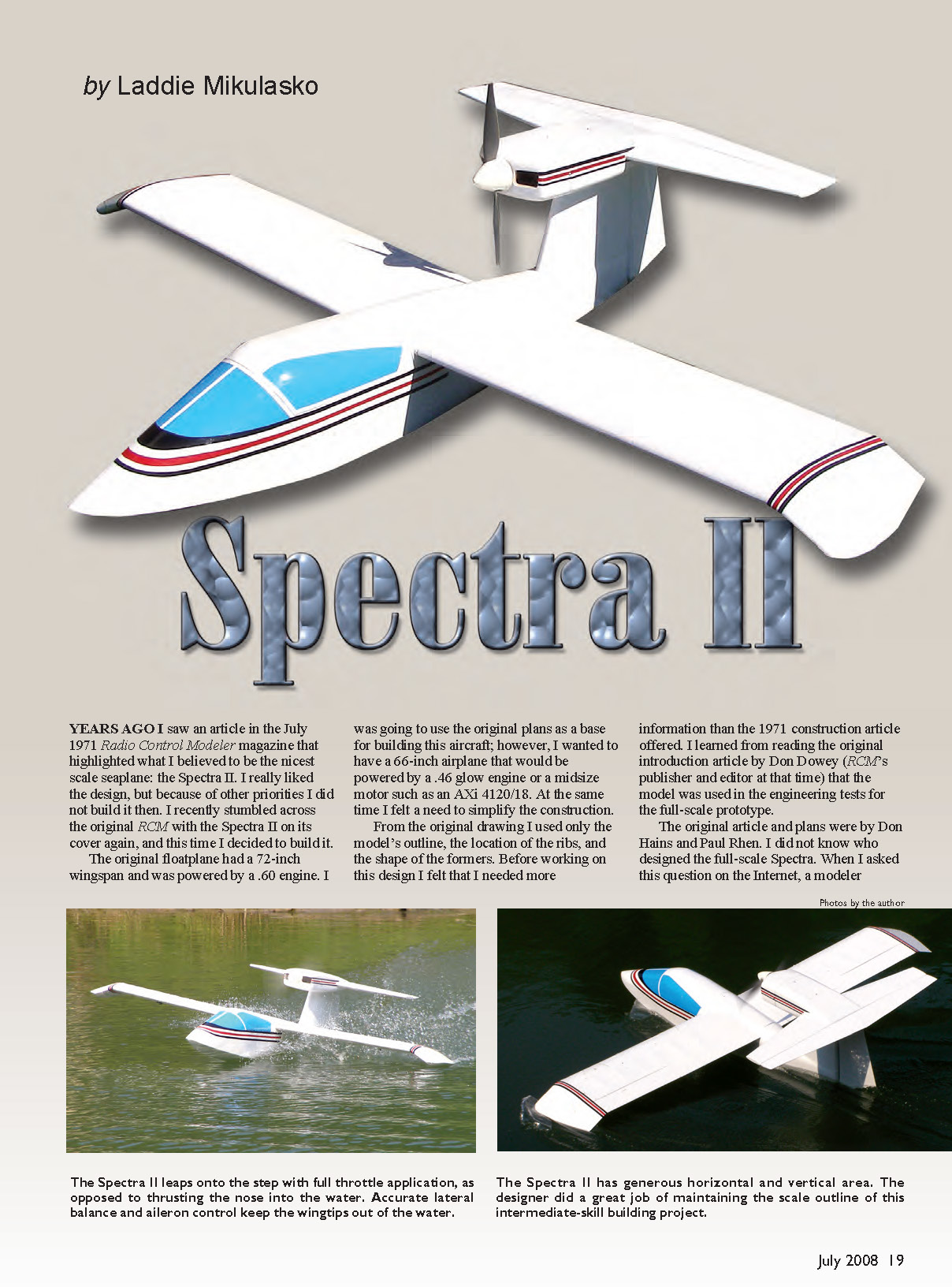
by Laddie Mikulasko
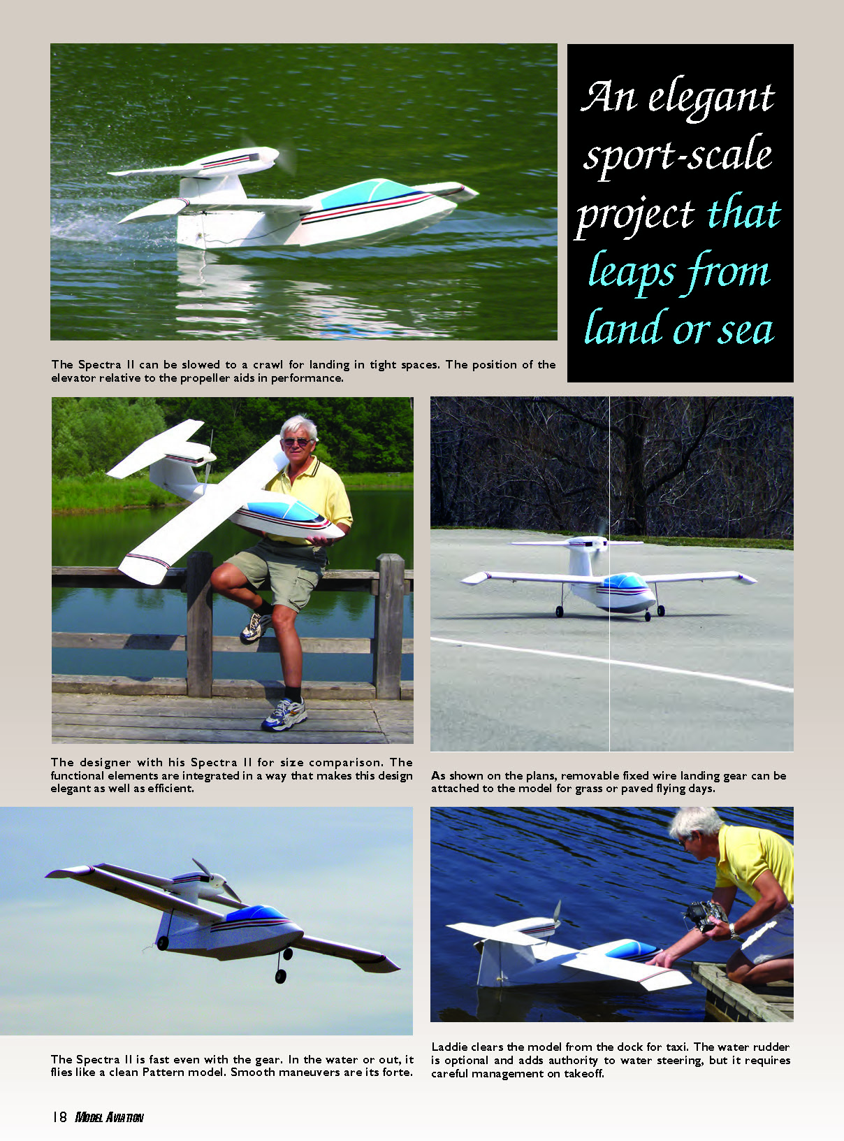
The Spectra II leaps onto the step with full-throttle application, as opposed to thrusting the nose into the water. Accurate lateral balance and aileron control keep the wingtips out of the water. The Spectra II has generous horizontal and vertical area. The designer did a great job of maintaining the scale outline of this intermediate-skill building project.
Years ago I saw an article in the July 1971 Radio Control Modeler that highlighted what I believed to be the nicest scale seaplane: the Spectra II. I really liked the design, but because of other priorities I did not build it then. I recently stumbled across the original RCM with the Spectra II on its cover again, and this time I decided to build it.
The original floatplane had a 72-inch wingspan and was powered by a .60 engine. I was going to use the original plans as a base for building this aircraft; however, I wanted to have a 66-inch airplane that would be powered by a .46 glow engine or a midsize motor such as an AXi 4120/18. At the same time I felt a need to simplify the construction. From the original drawing I used only the model’s outline, the location of the ribs, and the shape of the formers.
Before working on this design I felt that I needed more information than the 1971 construction article offered. I learned from reading the original introduction article by Don Dowey (RCM’s publisher and editor at that time) that the model was used in the engineering tests for the full-scale prototype. The original article and plans were by Don Hains and Paul Rhen. When I asked about the full-scale designer on the Internet, a modeler replied and enclosed part of the magazine article. Roy LoPresti was mentioned as the designer.
On the Internet I found LoPresti's company, Speed Merchants, which specializes in improving the performance of general-aviation aircraft by refining their aerodynamics. I contacted the company and received a reply from David LoPresti, who is the son of the company's founder. David wrote that his father terminated work on the Spectra for several reasons, one of which was that after the water-handling tests he concluded that he required a larger shop to continue.
David also mentioned that his father was planning to build a factory in Florida to produce the aircraft. For financial reasons that never happened. At that time David's father, who was employed by Grumman, was working on the moon program. Because of the program's cancellation, he was offered a chief engineer position at Grumman American in Ohio. The Spectra, an advanced design for its time, was never completed.
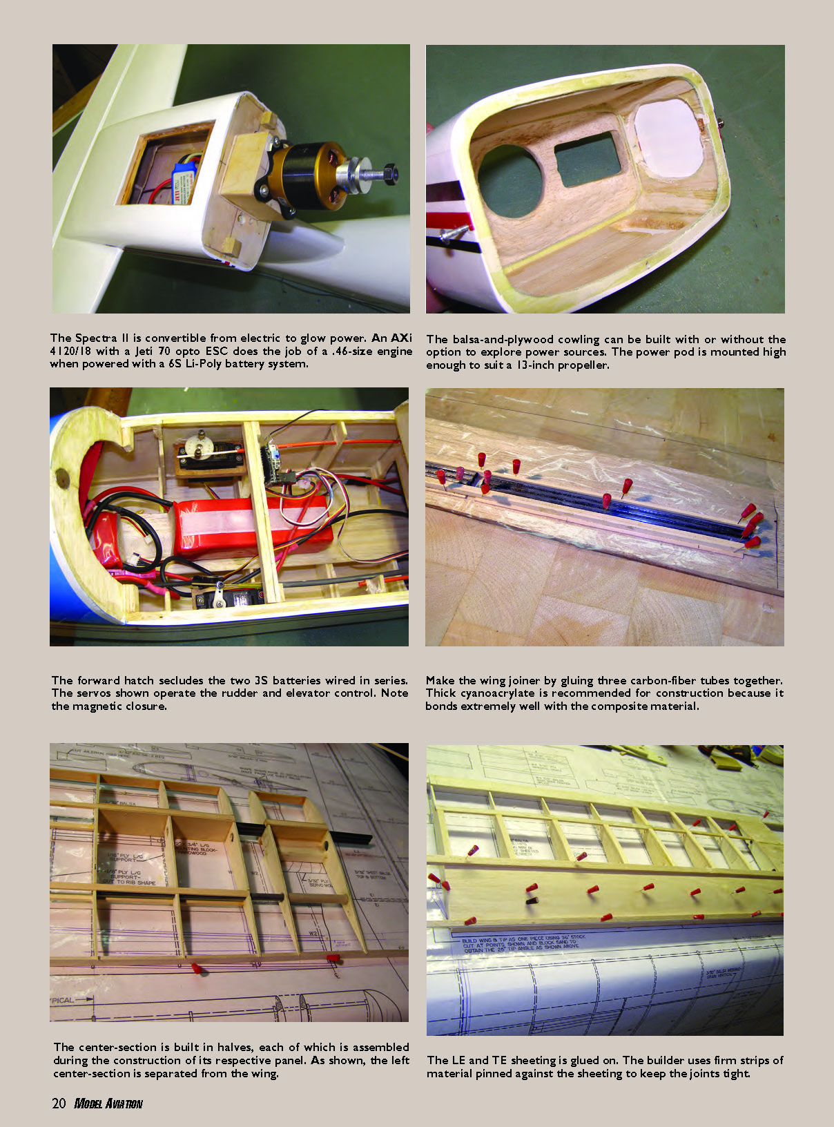
From the start I tried to design the model so that it would be easy to build. As I mentioned, I wanted an aircraft that could be flown either as glow or electric. Therefore, the nacelle can accommodate either power plant; it can house the fuel tank or a speed controller. The elevator and throttle servos can also be mounted inside the nacelle.
I made a plug-in wing to prevent the water from seeping into the fuselage. The Spectra II can easily be flown from both land and water.
To help less-experienced builders, I gave each part a number. The numbers are used to identify pieces in the construction section. Also use the included materials list as a cross-reference.
Please don't make modifications. I didn't use fiberglass on the outside of the model. Only the center-section of the wing, which sits inside the fuselage, has fiberglass on both the top and bottom to strengthen the wing joint point.
If you are planning to paint the fuselage, cover the entire thing with 3/4-ounce fiberglass. I recommend following the building sequence as written. As some photos show, parts of the Spectra II were built in different ways. I strongly suggest that you follow the written instructions.
CONSTRUCTION
Wing
- Make the two main joiners (24) by adhering three 1/4-inch-diameter carbon-fiber tubes with thick cyanoacrylate, as shown on the plans.
- Cut all the ribs. Cut and drill holes in the ribs as shown on the plans.
- Pin bottom main spar 1 to the building board over the plans. All wing spars are in three sections: the first section is between ribs W1 and W2, the second is between W3 and W11, and the third is on the wingtip between W12 and W13.
- Position and glue ribs W1–W11 onto the bottom main spar. Those ribs have to be angled as shown on the drawing. Slide the shim under the ribs' TEs. Glue top main spar 2 to all the ribs. Glue in top rear spar 7 to the ribs.
- Cut the aileron from the wing. Then glue hinge spar 13 to the ribs and to rear spars 6 and 7. Glue the aileron’s LE 14 to the aileron. Cap the ends of the aileron. Glue on the bottom sheeting between ribs W9 and W10. Glue on all the capstrips.
- Inside the aileron, glue the 1/8-inch plywood plate to the sheeting to support the aileron control horn.
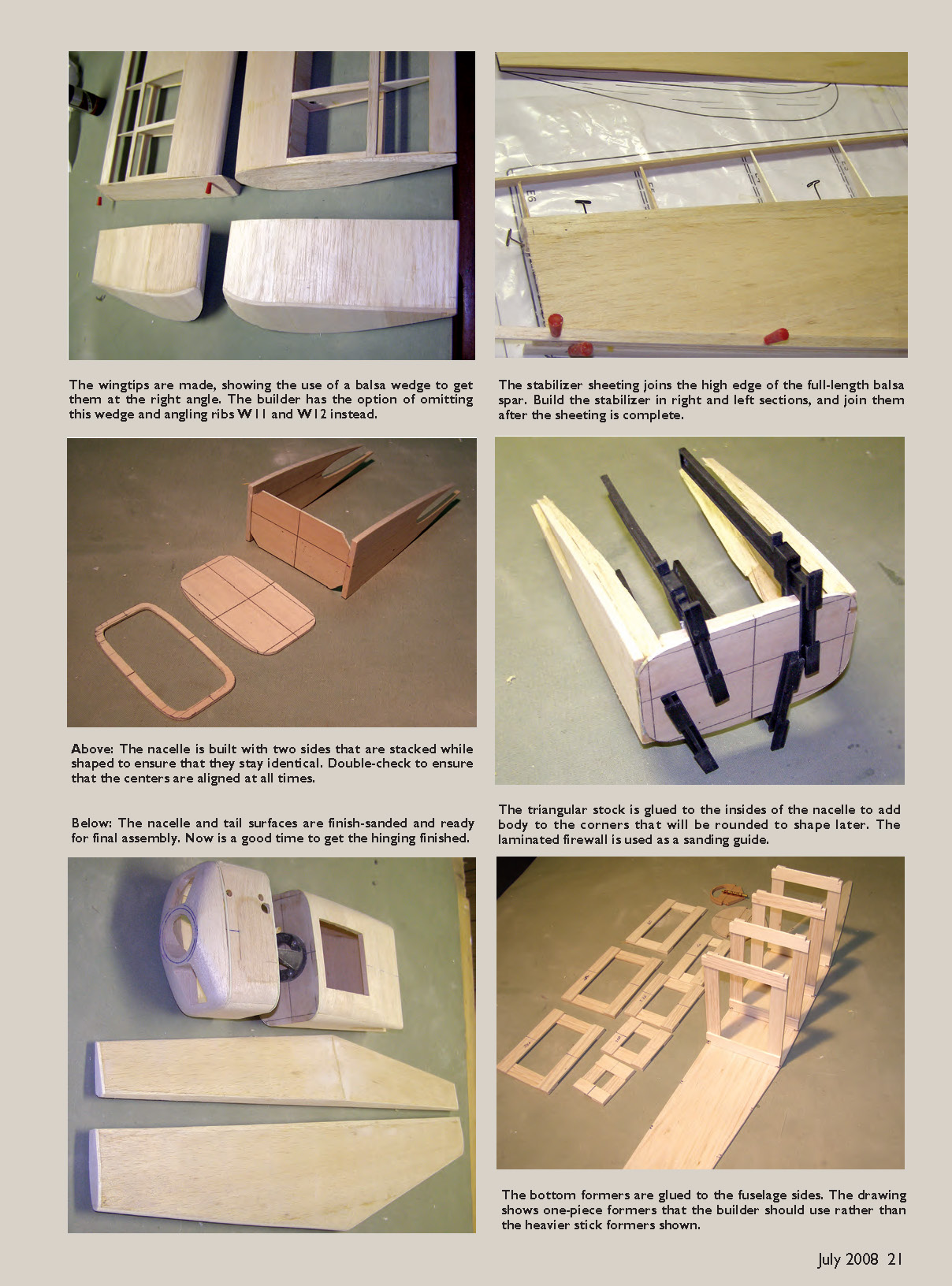
Wingtips
- Pin ribs W12 and W13 to the building board. Glue the main, rear, and LE spar to them. Make sure rib W12 is angled as shown on the drawing.
- Sheet both sides. The top sheeting has a different shape from the bottom one—refer to the drawing.
- Cap the end with balsa sheet 26. Glue the wingtips to the wing. Glue on LE capstrips 9. Sand the wing to its final shape.
Build the other wing half the same way. Plug each half into its center-section. Smear glue onto ribs W1 of each center-section. Join the halves and place the dihedral shim under each wingtip.
Once the halves are adhered, unplug the wing panels from the center-section. Cover both sides of the center-section with one layer of fiberglass. Pull in the extension wires for the aileron servos. Install the Y harness in the wing center-section.
Tail Surfaces
- The fin and rudder are made in left and right halves. Pin fin ribs FN1, FN2, and FN3 to the building board. Pin and glue fin LE 53 and hinge spar 55 to the ribs. The hinge spar extends up into the nacelle by 1/4 inch and all the way down into the fuselage.
- Glue on 1/8-inch carbon-fiber tube 52 to the ribs and to the hinge spar. Note that this tube extends up by 1/4 inch and down 2 1/4 inches.
- Glue on balsa sheeting 58 to the ribs, the LE, and the TE. Build the other half of the fin the same way.
- If you are planning to have the servos in front of the fuselage, install the plastic pushrods into the fin. If you are going to have the servos inside the nacelle, install the extension cables. If your Spectra II is going to be powered by a motor, install the battery extension and ESC extension wire leads.
- Insert and glue 1/4-inch carbon-fiber tube 51 to the ribs on one half of the fin, then glue the halves together. Note that this tube extends up by 1/4 inch and down by 3 inches, as did tube 52. Glue LE capstrip 54 to the fin and then sand the fin to its final shape.
Build the rudder in a similar fashion. Glue plywood plate 72 to the sheeting on the inside to support the rudder control horn. Glue plywood plate 73 to the bottom of the rudder; this will be needed to hold water rudder 74. The water rudder is made from thin sheet aluminum and must be removed when you are not flying from the water.
The stabilizer and elevator are built in left and right halves. Cut out all the ribs for those flying surfaces. Cut hinge spar 27 from 1/4-inch balsa sheet. Pin the hinge-spar shim to the building board and pin hinge spar 27 to the shim. Pin the LE shim to the building board and pin LE spar 28 to the shim.
Glue stabilizer ribs S1–S6 to the LE spar and the hinge spar. Glue top sheeting 30 to the ribs and the LE and TE. Flip the stabilizer upside down, pin to the shims, and glue on bottom sheeting 30. Glue on LE capstrip 29.
Build the elevator the same way, using the same shims. Do not forget to glue the plywood plate for the elevator control horn. Glue the stabilizer and elevator halves together. Sand them to their final shape.
Nacelle
- Cut plywood formers N1, N2, and N3. Cut out balsa sides 59 and 62. Glue the 1/2-inch triangular stock to the nacelle sides. Glue firewall N3 to the sides. Keep everything square.
- Glue on top sheeting 60 and bottom sheeting 61. Draw the centerline of the nacelle onto the top and bottom sheeting. In the top sheeting, cut the opening for the access hatch. On the bottom, cut the openings for the LE and the hinge spar of the fin to fit in. Make openings for the wires or plastic tubes to enter the nacelle from the fin.
- Make the engine cowl by gluing formers N1 and N2 to sides 62. Keep it square. Glue on top and bottom sheeting 63. Glue pre-shaped nose block 67 to the front of the cowl. Sand the nacelle and the cowl to their final shape.
Fuselage
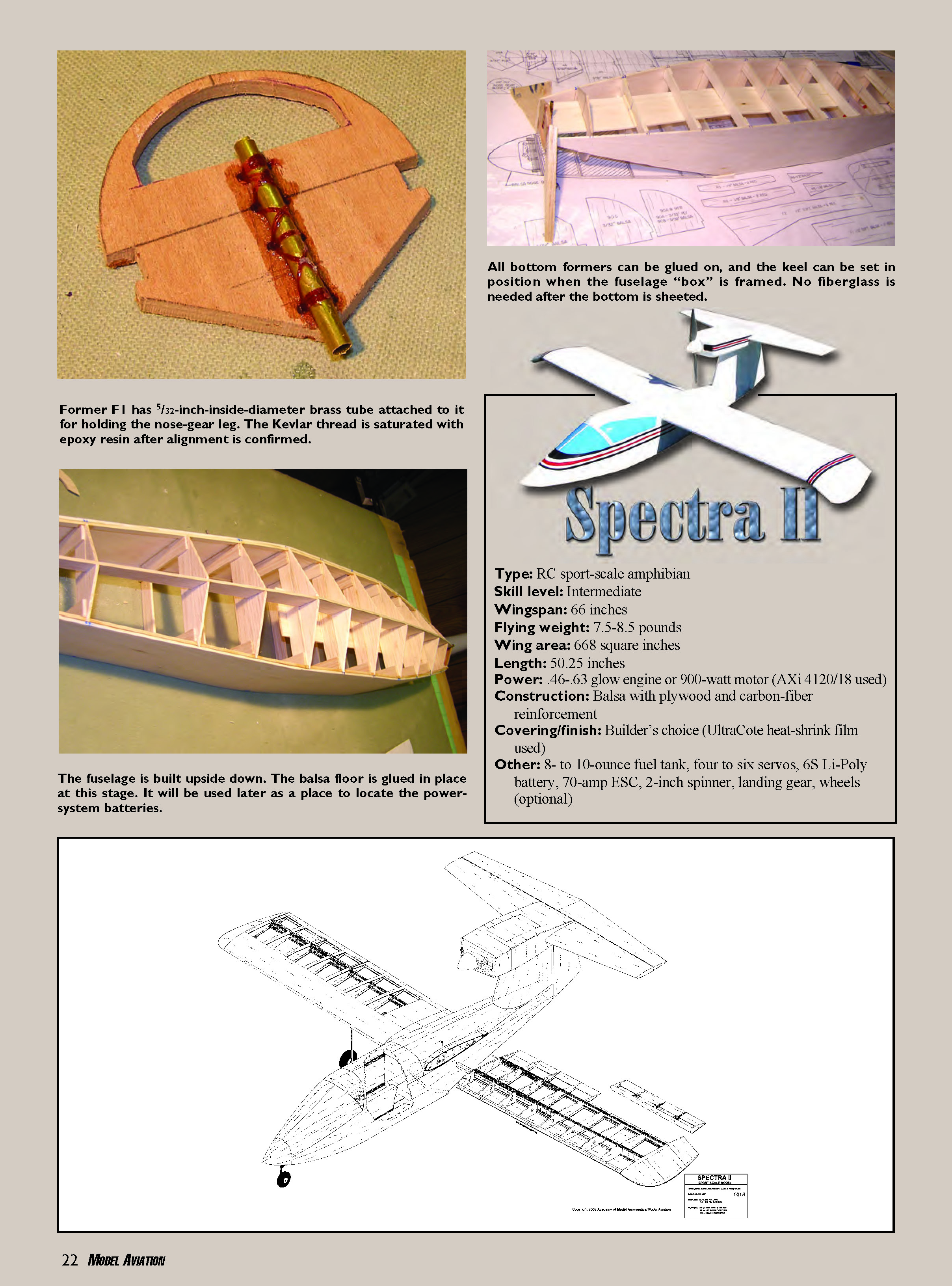
- Cut all formers and fuselage sides 35. Most of the formers are in top and bottom halves. Glue longerons 31, 32, 33, and 34 to the fuselage sides. Former F1 has a 5/32-inch brass tube attached to it with thread.
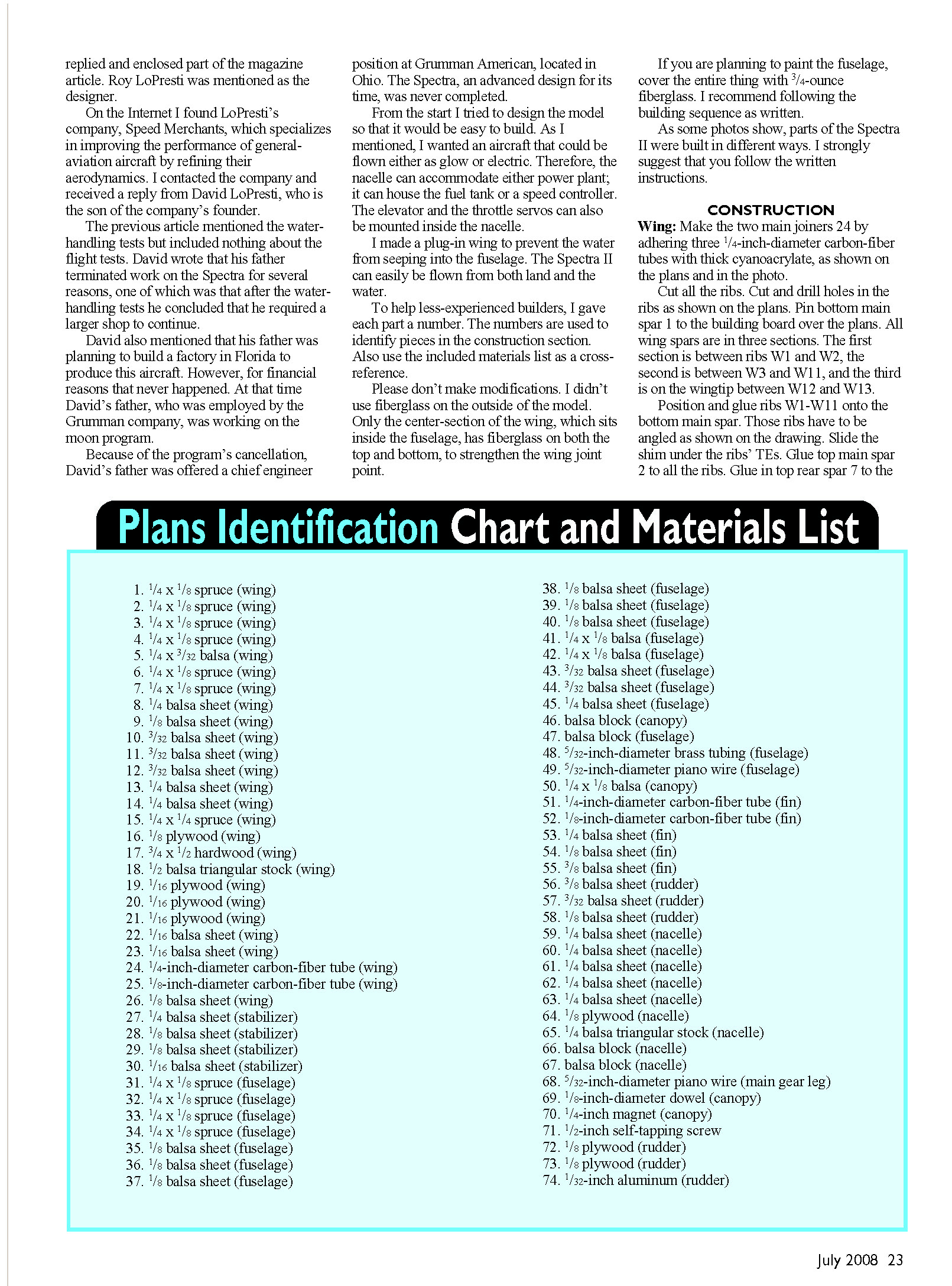
- Start building the fuselage upside-down. Glue bottom formers F5–F8 between the two fuselage sides 35. Glue in formers F1–F4. Glue the rest of the formers in the back of the fuselage. Glue in keels 37 and 39 to the formers.
- Glue on bottom sheeting 36 to formers F1–F8 and sheeting 38 to the formers behind the step. Turn the fuselage right-side up and glue in battery floor 40.
- Position the fin onto the fuselage. If you are using flexible control rods for controls, feed them through the holes in the formers and into the radio compartment. If you are using extension wires, pull them into the radio compartment. Glue the fin to the fuselage and make sure it is square with the sides.
- Glue on wing saddles 45 to each side of the fuselage. Smear epoxy onto the wing saddle. Place the wing on the wing saddle. Ensure that the wing panels are plugged into the center-section. Square the wing with the fuselage and let the epoxy harden.
- Unplug the wing panels from the fuselage. Glue the top half of formers F7, F9, and F10 to the fuselage and the top of former F8 to the wing center-section. Insert and glue longeron 42 into the slots in these formers. Glue on top sheeting 45 between formers F7 and F10.
- Glue on the top half of formers F3, F4, and F5A. Make sure former F5A is glued on the angle as shown on the drawing. Glue in top longeron 41. Glue on top sheeting 43 over formers F1–F5A. Glue balsa block 47 to the nose.
To make the canopy, place clear plastic on longerons inside the radio compartment so the glue does not stick to the fuselage when you are gluing the canopy pieces. Pin bottom frame pieces 50 to the fuselage. Glue formers F5B, F5C, F6, and F7A to frame piece 50. Glue top longeron 42 to F5C, F6, and F7A. Glue on canopy sheeting 44. Between former F5B and sheeting 44, glue in either a balsa block or a plank using balsa scraps.
The canopy is held in place with one dowel in the back and two 1/4-inch magnets embedded inside former F5A and F5B, or one 1/2-inch magnet in former F5A and the other in F5B.
Sand the fuselage to its final shape. Fix imperfections with filler—I used lightweight water-based filler.
I covered the model with iron-on material. If you are going to use a glow engine, cover the entire fuselage with fiberglass that is no heavier than 3/4 ounce per square foot, in preparation to finish with your favorite fuelproof paint.
Insert and glue in the stabilizer. Make sure it is square with the wing and the fuselage. Insert all the controls. Install the landing gear. The nose-wheel leg slides into the tubing. You can secure the steerable arm to it with the long Allen wrench. Mount the glow engine or motor.
With the glow engine, lead ballast has to be secured in the nose so the model can be balanced. If you are going to switch between glow and electric, do not glue the ballast into the nose. The electric-powered version does not need lead since the motor battery will be used to balance the model.
To secure the wing:
- Plug the wing panels into the fuselage.
- Drill a 3/32-inch hole 1/2-inch into the main spar of the center-section. The tip of the drill bit should penetrate the top carbon-fiber tube of the joiner but go no deeper. You must drill the hole approximately 1 inch in from W2 ribs.
- Drive a self-tapping screw in place. Test the security by trying to pull out the wing panels; they must not move.
Cover the model with your favorite material. Install the hardware and test everything before the first flight. Check the CG; it should be located as shown, with the fuel tank empty.
FLYING
When flying from a hard surface, taxi into the wind and apply full power. The Spectra II tracks straight and will rotate quickly. If balanced correctly, it will have a solid feel.
Despite the model being short-coupled, it is not sensitive in pitch. It can perform all basic maneuvers. Before landing, fly high and then try to slow the airplane until it stalls so you have an idea about its low-speed behavior.
When flying from water:
- Remove the landing gear and seal the gear sockets with matching covering or tape.
- In light wind there is no problem with steering. In a stronger crosswind, the airplane requires that the water-rudder extension be installed. You may choose to make a longer water rudder or add temporary extensions as needed.
- Taxi the model into the wind. Gradually apply full power. Lift the wingtips out of the water with the ailerons. The model will lift off quickly.
The Spectra II is a delight in the air, especially without the wire gear hanging from it. The elevator's location means that it stays effective at all speeds. The large amount of side area promotes good rudder authority for point rolls. Inverted flight is well within this model's capabilities.
I hope you enjoy building and flying the Spectra II as much as I did. Good luck.
Laddie Mikulasko 7 Giffen Rd. Dundas, Ontario L9H 6S1 Canada
Transcribed from original scans by AI. Minor OCR errors may remain.

