
Speed 400 Corsair
Jim Ryan
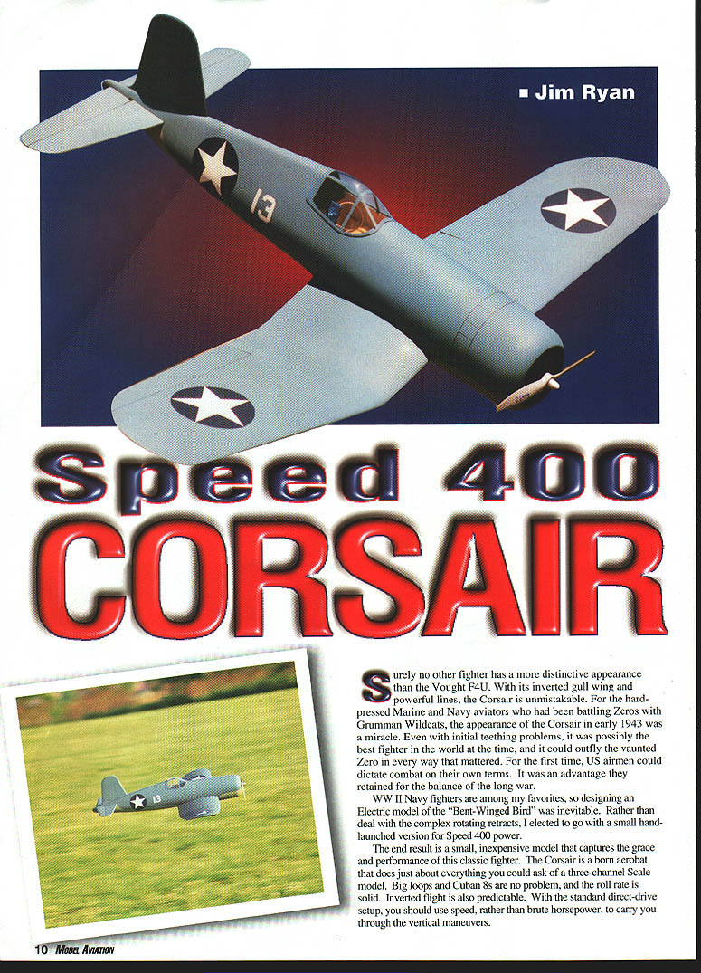
Surely no other fighter has a more distinctive appearance than the Vought F4U. With its inverted gull wing and powerful lines, the Corsair is unmistakable. For the hard-pressed Marine and Navy aviators who had been battling Zeros with Grumman Wildcats, the appearance of the Corsair in early 1943 was a miracle. Even with initial teething problems, it was possibly the best fighter in the world at the time, and it could outfly the vaunted Zero in every way that mattered. For the first time, US airmen could dictate combat on their own terms. It was an advantage they retained for the balance of the long war.
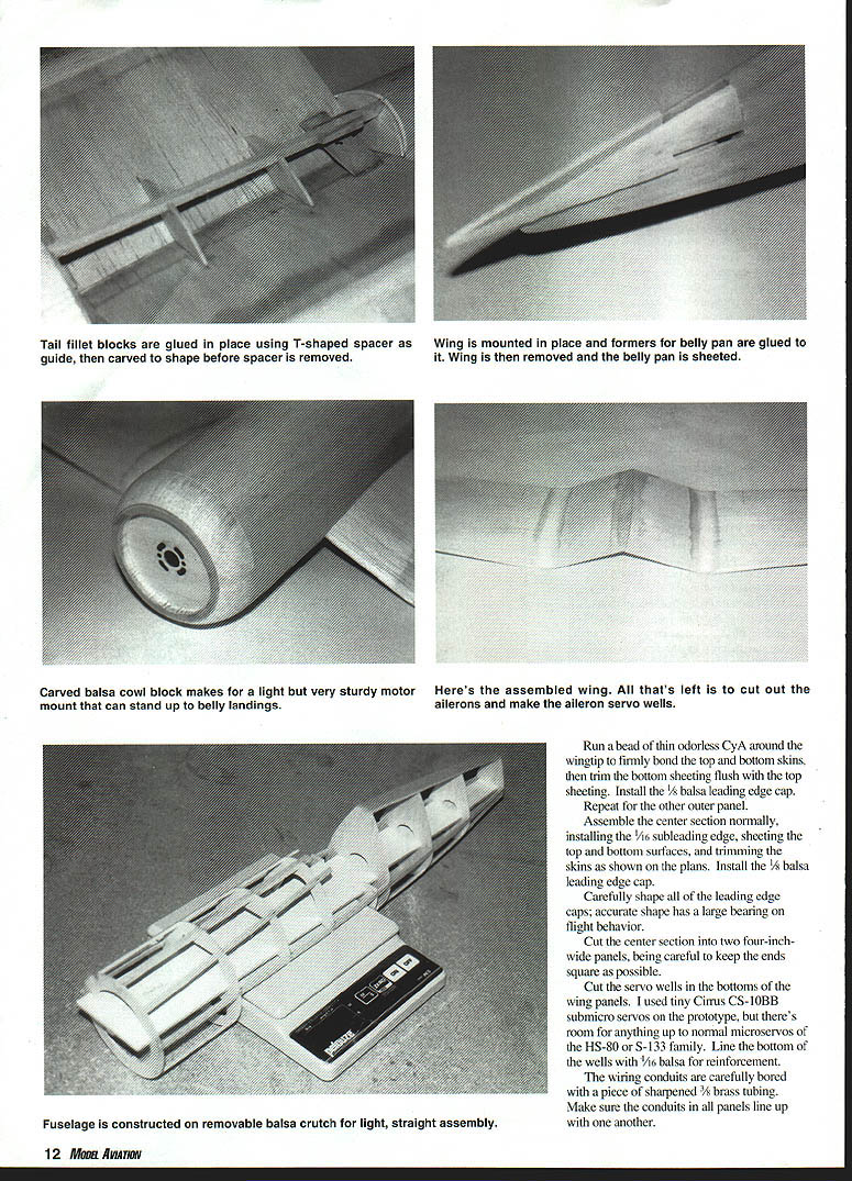
WW II Navy fighters are among my favorites, so designing an electric model of the "Bent-Winged Bird" was inevitable. Rather than deal with the complex rotating retracts, I elected to go with a small hand-launched version for Speed 400 power.
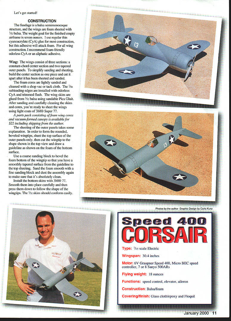
The end result is a small, inexpensive model that captures the grace and performance of this classic fighter. The Corsair is a barnstormer that does just about everything you could ask of a three-channel scale model. Big loops and Cuban 8s are no problem, and the roll rate is solid. Inverted flight is also predictable. With the standard direct-drive setup, you should use speed, rather than brute horsepower, to carry you through the vertical maneuvers.
Let's get started!
Construction
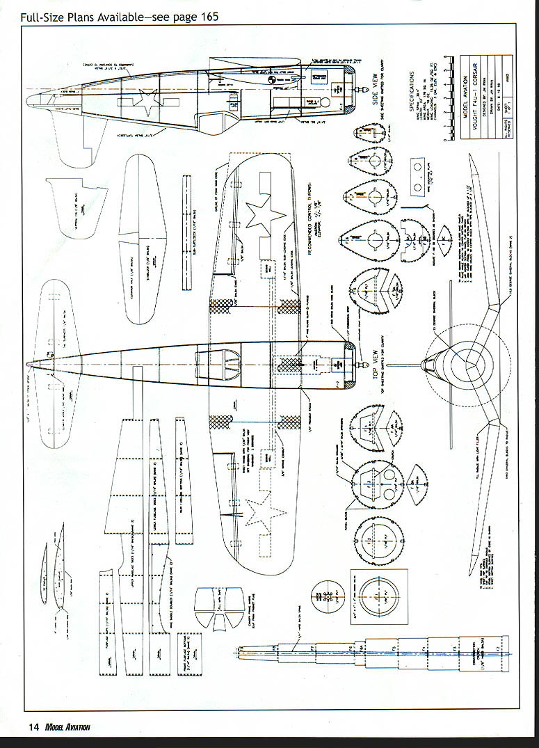
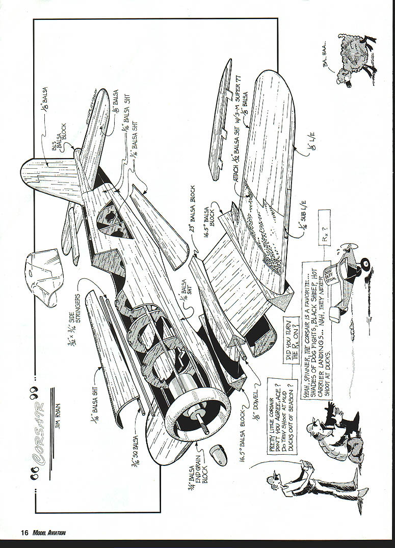
The fuselage is a balsa semi-monocoque structure, and the wings are foam sheeted with 1/32 balsa. The weight goal for the finished empty airframe is seven ounces. Use regular thin cyanoacrylate (CyA) glue for most construction, but this adhesive will attack foam. For all wing construction, I recommend foam-friendly odorless CyA or an aliphatic adhesive.
Wing
The wings consist of three sections: a constant-chord center section and two tapered outer panels. To simplify sanding and sheeting, build the center section as one piece and cut it apart after it has been sheeted and sanded. The foam cores are lightly sanded and cleaned with a shop vac or tack cloth. The 1/16 subleading edges are installed with odorless CyA and trimmed flush. The wing skins are glued from 1/32 balsa using sandable Pica Glu-It. After sanding and carefully cleaning the skins and cores, you're ready to sheet the wings using light coats of 3M® Super 77.
The sheeting of the outer panels takes some explanation. In order to form the rounded, beveled wingtips:
- Sheet the top surface of the outer panels only.
- Cut the wingtip to the shape shown in the top view and draw a guideline on the foam of the bottom surface.
- Use a coarse sanding block to bevel the foam bottom of the wingtip so that you have a smoothly tapered surface from the guideline to the top sheeting.
- Sand the foam smooth with a fine sanding block and dust the assembly again to make sure that it's absolutely clean.
- Install the bottom skins with 3M® 77. Smooth them into place carefully and then press them down to follow the shape of the wingtips. The 1/32 skins should conform easily.
Run a bead of thin odorless CyA around the wingtip to firmly bond the top and bottom skins, then trim the bottom sheeting flush with the top sheeting. Install the 1/8 balsa leading edge cap. Repeat for the other outer panel.
Assemble the center section normally, installing the 1/16 subleading edge, sheeting the top and bottom surfaces, and trimming the skins as shown on the plans. Install the 1/8 balsa leading edge cap. Carefully shape all of the leading edge caps; accurate shape has a large bearing on flight behavior.
Cut the center section into two four-inch-wide panels, being careful to keep the ends as square as possible.
Cut the servo wells in the bottoms of the wing panels. I used tiny Cirrus CS-10BB submicro servos on the prototype, but there's room for anything up to normal micro servos of the HS-80 or S-133 family. Line the bottom of the wells with 1/16 balsa for reinforcement.
The wiring conduits are carefully bored with a piece of sharpened 3/32-inch brass tubing. Make sure the conduits in all panels line up with one another.
Joining the Wing Panels
The 16.5° soft balsa angle blocks at the wing joints allow you to produce a scale-like radius where the wings bend.
- Begin by using the wing panels to mark the upper surface of the airfoils on both faces of the angle blocks and then trim them to shape. Do not shape the bottom surface at this time, as this aids in wing alignment during assembly.
- Bore holes in the blocks for the aileron leads.
- Use thick odorless CyA to glue an angle block to each center section panel (be sure you make a left and a right wing).
- With the center section resting flat on your building board, glue the outer panel to the other side of the angle block. Block the tip up 6½ inches above your work surface and allow the assembly to cure.
- When dry, use a sanding block to shape the angle blocks to a gentle radius as shown on the front view in the plans.
Use the same technique to preshape the 23° center angle block, and use it to join the wings. This time, block up the assembly so that the wingtips are 2½ inches above your building board.
Shape fillets on the top surface of the wings to make a smooth radius as shown in the front view. I recommend applying masking tape 1/2 inch from the center of the angle block and then spreading lite spackle with a credit card and allowing it to dry at least overnight before sanding to shape.
When you're happy with the appearance, glass the wing joints with 1½-inch-wide strips of two-ounce glass cloth and thin odorless CyA. Sand the joints smooth, and the basic wing is complete.
Control Surfaces
Cut the ailerons from the wing panels as shown on the plan view and scarf 1/8 balsa to the exposed trailing edge. Trim 1/4" from the leading edges of the ailerons and install their 1/8 balsa caps.
The ailerons are 1/8 balsa sheeted on 1/8 balsa stock. Sheet the ailerons top and bottom and sand to shape. Hinge the ailerons with thin CA hinges or use tape hinges if you prefer. Reinforce the servo mounting areas with 1/32 plywood doublers. Mount the servos on plywood rails glued into the wing bays. Use pushrods that are as direct as possible to minimize slop.
Wing Installation and Belly Pan
Test-fit the wing in the wing saddle. You can get a tighter joint by slipping a strip of fine sandpaper into the joint and sliding it back and forth to "lap" the saddle, but don't get carried away—you don't want to change the incidence!
Tap the 1/8 plywood wing mount for a 6-32 nylon screw, glue the mount in place in the fuselage, and reinforce the joint with 1/4 balsa triangle stock. Drill the screw hole through the wing and install the 6-32 nylon wing screw. Square the wing with the tail, pinning it in place in the proper position. Drill the leading edge of the wing to accept the 1/8 locator dowel (a long drill or round X-Acto® file can go right through the opening in F-2).
Remove the wing, install the dowel, and reinstall the wing with a sheet of waxed paper sandwiched between the wing and fuselage. Install the belly pan formers on the bottom of the wing, being careful not to glue them to the fuselage.
Glue the front and back formers (F-3A and F-6C) in place, then dry-fit the keel stringer. Slip the middle two formers (F-4A and F-5A) in place. If necessary, trim them so they can fit without bowing the keel stringer upward; this makes the belly pan much easier to plank.
Remove the wing from the fuselage and install the 1/16 belly pan sheeting. It's easiest if you do this with separate halves and trim them so that they join tightly over the 3/16 keel stringer. Trim and sand the front and rear edges flush with the formers.
Cut a 1/8 access hole over the wing hold-down screw and reinstall the wing on the fuselage. Sand the joint between the belly pan and fuselage sheeting flush, being careful not to sand through the sheeting.
Empennage
Assemble the wing to the fuselage and trial-fit the stab on the stab base. Make certain the stab is parallel to the wing, and if necessary, sand the base or add shims to correct any error. Remove the wing and stab and glue the tail fillet blocks into place using a T-shaped 1/4 balsa spacer as a guide (be careful not to glue the spacer in place). Carve and sand the tail fillets to shape.
The balsa spacer is now removed from the tail fillet. If you've been careful with the glue, it should slide right out. Add a 1/8 balsa spacer to support the tail fillets behind the stab, but make sure you leave room for the music wire elevator joiner.
Cut a slot in the turtledeck to accept the key at the forward end of the vertical fin. Dry-fit the vertical fin and stabilizer and test-install a 1/16 music wire elevator joiner (if you prefer, you can use a 5/32 dowel joiner).
I found it best to wait and permanently install the vertical fin and stabilizer after covering.
Tail surfaces:
- The stabilizer and fin are built up from 1/8 sheet with 1/16 balsa trailing edges.
- Sand the airfoils carefully and reinforce the stab center with a 1/8 x 1/4 balsa spacer that will be glued into the fuselage saddle.
- The elevator and rudder hinge with 1/8 diameter nylon hinges.
- Install a 1/16 music wire elevator joiner and secure it with cyanoacrylate and a small dab of epoxy for strength.
Cowl Block
The cowl is a 3/4-inch-thick block of end-grain balsa that is carved to shape. Note that the block is bored for the motor opening and a 1/4-inch-wide strip of cross-grain balsa is glued in place to provide a shoulder for positioning the motor mount.
Draw datum lines on the front of the block and use them as a guide for installing F-1, F-1A and F-1B formers. Glue the formers into place and trim the cowl block to match the fuselage sides and tops. Carefully sand the cowl fairing to shape.
Finish the cowl with glass cloth and epoxy, then sand and paint to match the rest of the model.
Fuselage
The fuselage is a semi-monocoque shell built over bulkheads F-1 through F-6. Glue the fuselage sides to the formers and add the 1/8 balsa stringers. Sheet the top and bottom of the fuselage with 1/16 balsa, leaving the battery and radio hatch areas open.
Install the motor mount shoulder in the cowl block as described above and epoxy the mount into the nose assembly. Fit the cowl to the nose and finish the cowl with glass cloth and epoxy.
The fuselage is built as a semi-monocoque structure using 1/16 and 1/8 balsa. The motor bulkhead is 1/8 plywood and is glued in place with epoxy. Install the wing saddle doublers and glue the wing center section in place. Form the turtledeck and top decking from 1/16 balsa, scarfing the joints for strength. The cockpit area is cut from the balsa and fitted with the vacuum-formed canopy. The canopy is cemented in place and the windshield area is reinforced from the inside with glass cloth and epoxy.
Landing Gear
This model uses fixed spats made from 1/8 balsa blocks hollowed to accept the Speed 400 motor’s thrust loads. Shape the spats and sheeting to match the scale appearance and reinforce the gear mounts with plywood doublers where necessary.
Radio and Power Installation
- Use a 3-channel radio for throttle, elevator and aileron control.
- Mount the receiver and battery low in the fuselage for best longitudinal stability.
- A Micro BEC speed controller is recommended with the Graupner Speed 400 motor and seven or eight Sanyo 500AR cells.
- The Speed 400 motor is mounted on the plywood motor mount with 1/16-inch spacers as shown on the plans.
- Mount the Ni-Cd pack so that it can be removed for charging; Velcro straps work well.
- Install the receiver low in the fuselage and keep the servos close to the control surfaces.
- Use .038 music wire for the pushrods to keep weight to a minimum. Another option for the elevator is to use Teleflex or pull-pull cables. If you opt for music wire, Sullivan 2-56 brass couplers (part #512) are suggested; solder them in place and add a small nylon clevis.
Cut the battery mounting plate from 1/16 balsa and install it on F-3 and F-4, using 1/4 triangle stock to reinforce the joint. Apply a strip of Velcro to the mounting plate so that the Ni-Cd pack can be secured. The servos can be secured with double-stick mounting tape.
Covering and Finish
Finish the model with glass cloth and epoxy over the nose and cowl areas, and use lightweight tissue or film covering on the wings and tail if desired. The model in the photos was finished with Floquil enamels and scale markings.
As one of the longest-serving piston-engine fighters of all time, the Corsair gives you plenty of choices for color schemes. For small Navy models like this, Corsair Blue Goldberg UltraCote is a great choice; it looks scale and is very light. The prototype was covered with .56-ounce fiberglass cloth and epoxy and painted with Floquil military paints.
The canopy framing can be painted using the frisket masks shown in the plans. Make sure you protect the inside surface of the canopy from overspray. After painting the framing, remove the masks and glue the canopy in place with RC-56 or equivalent canopy glue.
Install the hardware, and you're ready to go fly.
Flying
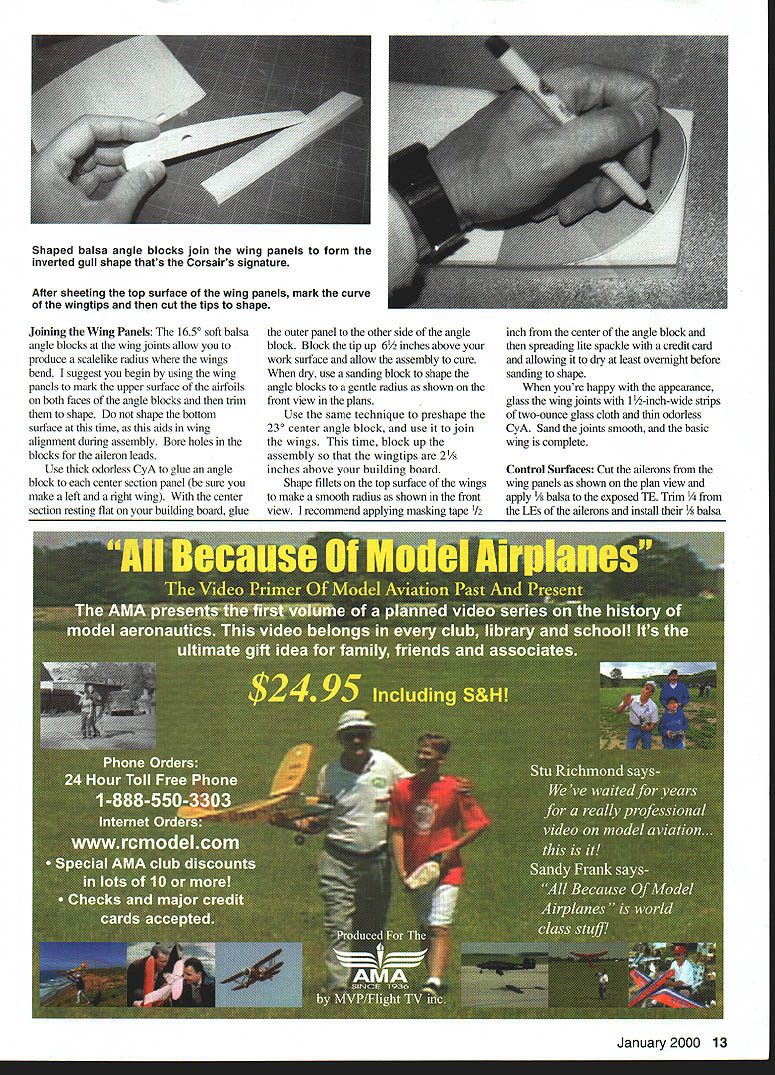
The finished model weighs about 18 ounces and has a wingspan of 30.4 inches. With the direct-drive Speed 400 setup, use speed rather than brute horsepower to carry you through vertical maneuvers. The Corsair is capable of big loops, Cuban 8s, rolls and predictable inverted flight. Adjust the control throws for smooth, scale-like responses and balance the model at the recommended center of gravity before the first flight.
Flight testing notes:
- Be very careful checking the center of gravity (CG); small warbirds aren't very tolerant of an aft CG condition. Start with the balance point two inches behind the leading edge of the wing and adjust to suit.
- I strongly recommend getting a capable assistant to hand-launch the model on the first flights. The model needs to be thrown straight and level; if the launcher lobs it upward, it's likely to stall. Hold the wings level and let it climb slowly as the speed builds up.
- Landings are made with a straight-in approach, and the model is simply held just off the ground until it settles in. The Corsair has little inclination to tipstall, and landings are a breeze.
It was the Corsair, thanks to the 1970s TV series Baa Baa Black Sheep, that first kindled my interest in RC modeling, and after 25 years, I finally have one.
It was worth the wait!
Jim Ryan 6941 Roby Vern Dr. Cincinnati OH 45239 (513) 729-3323 [email protected]
Transcribed from original scans by AI. Minor OCR errors may remain.

