
Sport Scale PT-19
by Charles S. Pipes
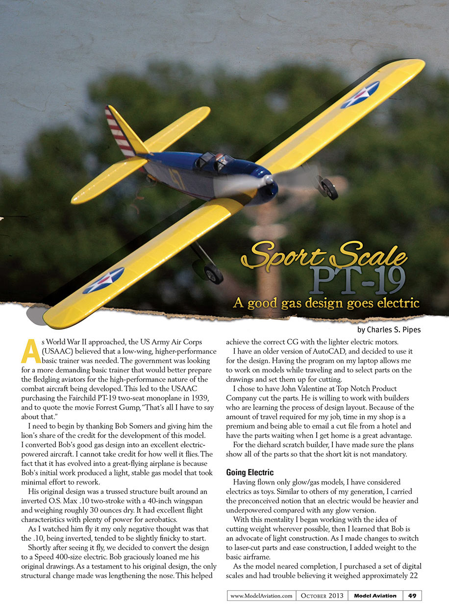
As World War II approached, the US Army Air Corps (USAAC) believed that a low-wing, higher-performance basic trainer was needed. The government was looking for a more demanding basic trainer that would better prepare the fledgling aviators for the high-performance nature of the combat aircraft being developed. This led to the USAAC purchasing the Fairchild PT-19 two-seat monoplane in 1939, and to quote the movie Forrest Gump, "That's all I have to say about that."
I need to begin by thanking Bob Somers and giving him the lion's share of the credit for the development of this model. I converted Bob's good gas design into an excellent electric-powered aircraft. I cannot take credit for how well it flies. The fact that it has evolved into a great-flying airplane is because Bob's initial work produced a light, stable gas model that took minimal effort to rework.
His original design was a trussed structure built around an inverted O.S. Max .10 two-stroke with a 40-inch wingspan and weighing roughly 30 ounces dry. It had excellent flight characteristics with plenty of power for aerobatics.
As I watched him fly it my only negative thought was that the .10, being inverted, tended to be slightly finicky to start.
Shortly after seeing it fly, we decided to convert the design to a Speed 400-size electric. Bob graciously loaned me his original drawings. As a testament to his original design, the only structural change made was lengthening the nose. This helped achieve the correct CG with the lighter electric motors.
I have an older version of AutoCAD, and decided to use it for the design. Having the program on my laptop allows me to work on models while traveling and to select parts on the drawings and set them up for cutting.
I chose to have John Valentine at Top Notch Product Company cut the parts. He is willing to work with builders who are learning the process of design layout. Because of the amount of travel required for my job, time in my shop is a premium and being able to email a cut file from a hotel and have the parts waiting when I get home is a great advantage.
For the diehard scratch builder, I have made sure the plans show all of the parts so that the short kit is not mandatory.
Going Electric
Having flown only glow/gas models, I have considered electrics as toys. Similar to others of my generation, I carried the preconceived notion that an electric would be heavier and underpowered compared with any glow version.
With this mentality I began working with the idea of cutting weight wherever possible, then I learned that Bob is an advocate of light construction. As I made changes to switch to laser-cut parts and ease construction, I added weight to the basic airframe.
As the model neared completion, I purchased a set of digital scales and had trouble believing it weighed approximately 22 ounces with a 1,650 mAh LiPo. Bob and I have concluded that the weight savings was because of the availability of all of the new, lightweight electric hardware.
The electric motor, ESC, and battery weigh significantly less than the .10-size engine, fuel tank, tubing, and the throttle servo and its linkage. Other weight savings can be attributed to using the lighter microreceivers, servos, foam wheels, and lighter hardware. Using Solarfilm instead of MonoKote also reduced the weight.
Features
The initial effort was a trace of Bob’s design where I laid out the parts in CAD and replaced the .10 O.S. Max engine with an E-flite 450 brushless outrunner. I carried the fuselage sides past the original firewall and drew the electric motor mounted to a laminated nose block ending in a plywood nose plate.
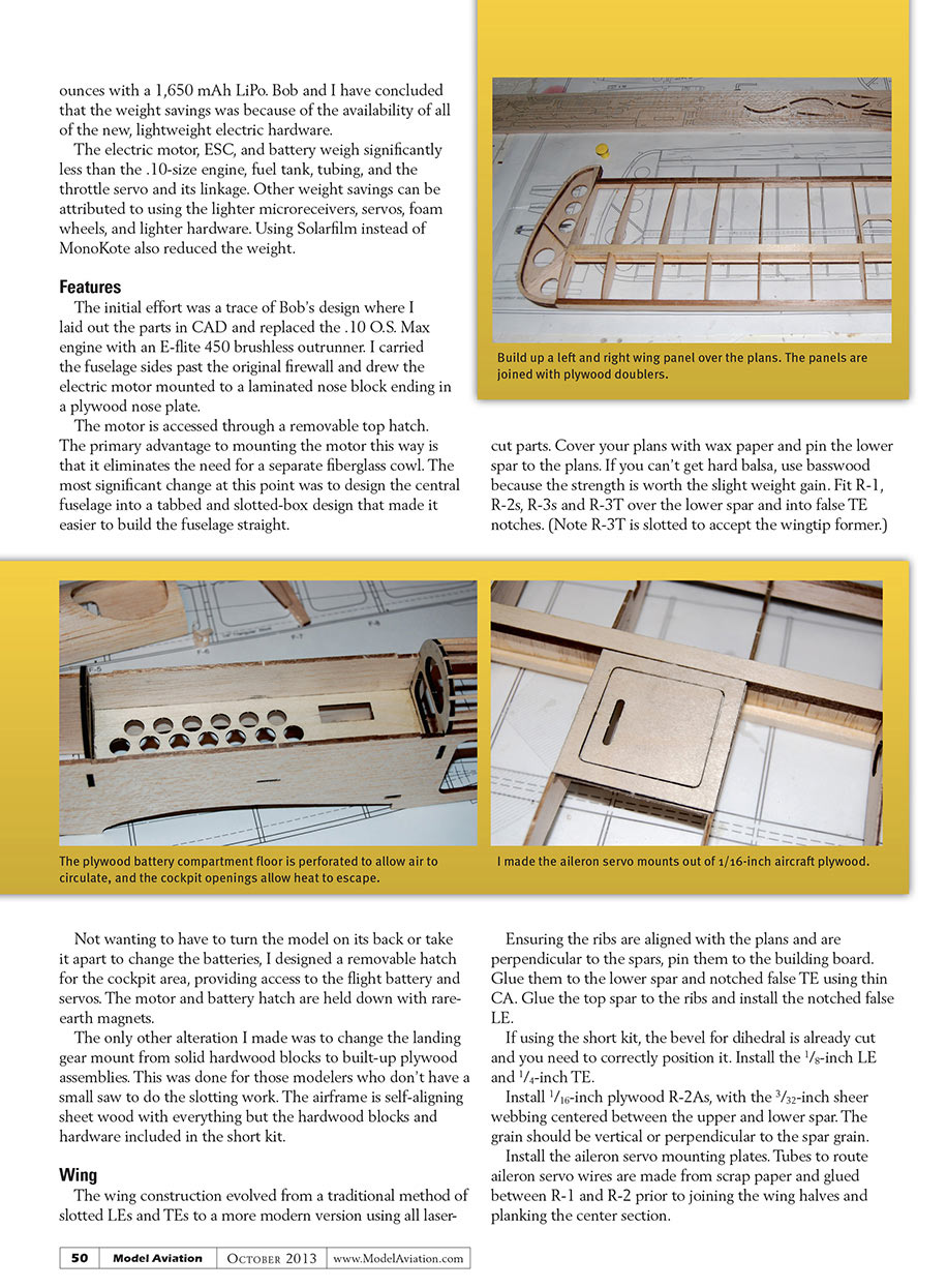
The motor is accessed through a removable top hatch. The primary advantage to mounting the motor this way is that it eliminates the need for a separate fiberglass cowl. The most significant change at this point was to design the central fuselage into a tabbed and slotted-box design that made it easier to build the fuselage straight.
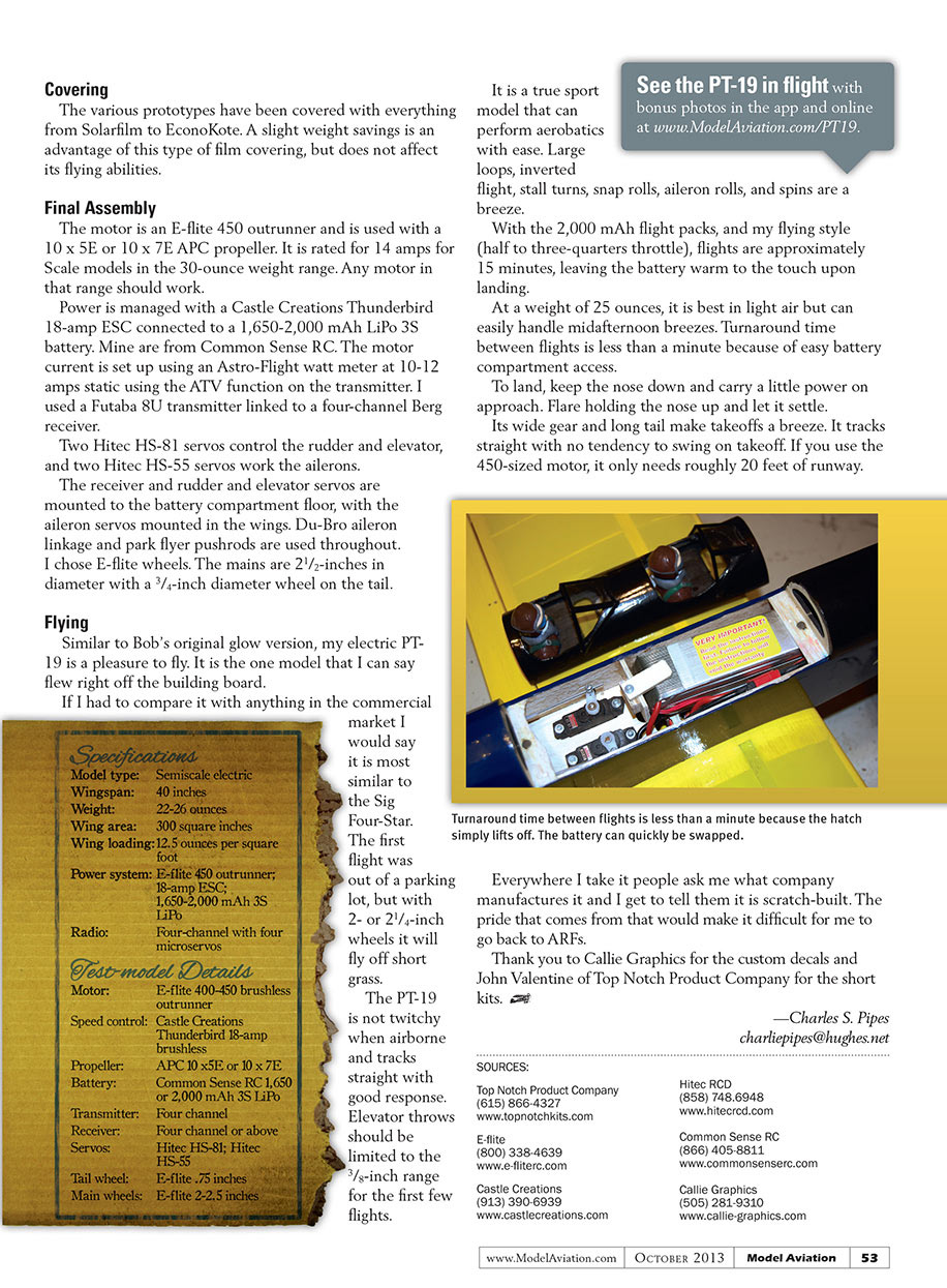
Not wanting to have to turn the model on its back or take it apart to change the batteries, I designed a removable hatch for the cockpit area, providing access to the flight battery and servos. The motor and battery hatch are held down with rare-earth magnets.
The only other alteration I made was to change the landing gear mount from solid hardwood blocks to built-up plywood assemblies. This was done for those modelers who don’t have a small saw to do the slotting work. The airframe is self-aligning sheet wood with everything but the hardwood blocks and hardware included in the short kit.
Wing
The wing construction evolved from a traditional method of slotted LEs and TEs to a more modern version using all laser-cut parts. Cover your plans with wax paper and pin the lower spar to the plans. If you can’t get hard balsa, use basswood because the strength is worth the slight weight gain. Fit R-1, R-2s, R-3s and R-3T over the lower spar and into false TE notches. (Note R-3T is slotted to accept the wingtip former.)
Ensuring the ribs are aligned with the plans and are perpendicular to the spars, pin them to the building board. Glue them to the lower spar and notched false TE using thin CA. Glue the top spar to the ribs and install the notched false LE.
If using the short kit, the bevel for dihedral is already cut and you need to correctly position it. Install the 1/8-inch LE and 1/4-inch TE.
Install 1/16-inch plywood R-2As, with the 3/32-inch sheer webbing centered between the upper and lower spar. The grain should be vertical or perpendicular to the spar grain.
Install the aileron servo mounting plates. Tubes to route aileron servo wires are made from scrap paper and glued between R-1 and R-2 prior to joining the wing halves and planking the center section.
Shape the LEs and TEs using a razor plane and sanding blocks. Glue the wingtip formers to R-3T. Glue the wingtip braces R-5 through R-8 to the top and bottom of the wingtip formers—this will require bevel sanding for proper fit where the braces meet R-3T.
Glue a set of T-1, T-2, and T-3 to the top and bottom of each wingtip. Glue T-9 to the top and bottom of each wingtip. Shape the wingtip with a razor plane and sanding blocks.
The wing panels are joined with epoxied 1/8-inch plywood doublers. Install the 1/8-inch center rib to allow for 1/16-inch planking.
Install 1/16-inch square stock across the LE spar and the TE to give the center planking something to adhere to. Plank the center section using 1/16-inch balsa. Install a 3/16-inch dowel in the wing's center.
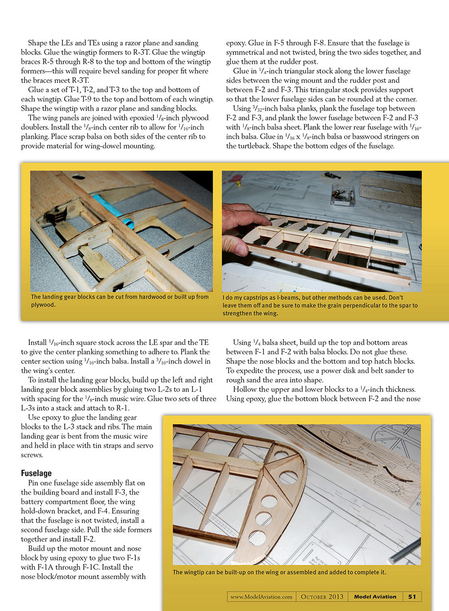
To install the landing gear blocks, build up the left and right landing gear block assemblies by gluing two L-2s to an L-1 with spacing for the 1/8-inch music wire. Glue two sets of three L-3s into a stack and attach to R-1.
Use epoxy to glue the landing gear blocks to the L-3 stack and ribs. The main landing gear is bent from the music wire and held in place with tin straps and servo screws.
Fuselage
Pin one fuselage side assembly flat on the building board and install F-3, the battery compartment floor, the wing hold-down bracket, and F-4. Ensuring that the fuselage is not twisted, install a second fuselage side. Pull the side formers together and install F-2.
Build up the motor mount and nose block by using epoxy to glue two F-1s with F-1A through F-1C. Install the nose block/motor mount assembly with epoxy. Glue in F-5 through F-8. Ensure that the fuselage is symmetrical and not twisted, bring the two sides together, and glue them at the rudder post.
Glue in 1/4-inch triangular stock along the lower fuselage sides between the wing mount and the rudder post and between F-2 and F-3. This triangular stock provides support so that the lower fuselage sides can be rounded at the corner. Using 3/32-inch balsa planks, plank the fuselage top between F-2 and F-3, and plank the lower fuselage between F-2 and F-3 with 1/8-inch balsa sheet. Plank the lower rear fuselage with 1/16-inch balsa. Glue in 1/16 x 1/8-inch balsa or basswood stringers on the turtleback. Shape the bottom edges of the fuselage.
Using 1/4 balsa sheet, build up the top and bottom areas between F-1 and F-2 with balsa blocks. Do not glue these. Shape the nose blocks and the bottom and top hatch blocks. To expedite the process, use a power disk and belt sander to rough sand the area into shape.
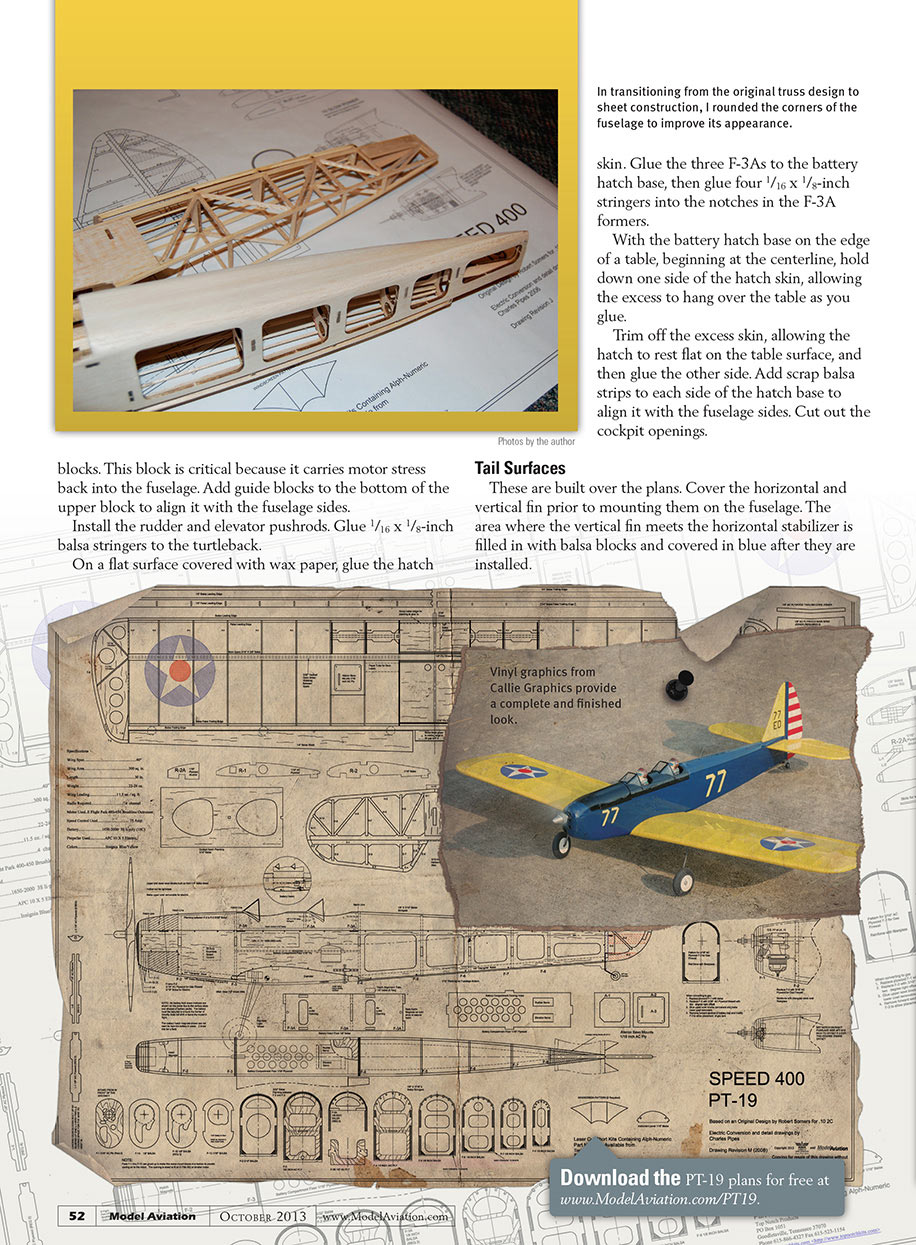
Hollow the upper and lower blocks to a 1/4-inch thickness. Using epoxy, glue the bottom block between F-2 and the nose skin. In transitioning from the original truss design to sheet construction, I rounded the corners of the fuselage to improve its appearance.
Glue the three F-3As to the battery hatch base, then glue four 1/16 x 1/8-inch stringers into the notches in the F-3A formers.
With the battery hatch base on the edge of a table, beginning at the centerline, hold down one side of the hatch skin, allowing the excess to hang over the table as you glue.
Trim off the excess skin, allowing the hatch to rest flat on the table surface, and then glue the other side. Add scrap balsa strips to each side of the hatch base to align it with the fuselage sides. Cut out the cockpit openings.
Tail Surfaces
These are built over the plans. Cover the horizontal and vertical fin prior to mounting them on the fuselage. The area where the vertical fin meets the horizontal stabilizer is filled in with balsa blocks and covered in blue after they are installed.
Covering
The various prototypes have been covered with everything from Solarfilm to EconoKote. A slight weight savings is an advantage of this type of film covering, but does not affect its flying abilities.
Final Assembly
The motor is an E-flite 450 outrunner and is used with a 10 x 5E or 10 x 7E APC propeller. It is rated for 14 amps for Scale models in the 30-ounce weight range. Any motor in that range should work.
Power is managed with a Castle Creations Thunderbird 18-amp ESC connected to a 1,650–2,000 mAh LiPo 3S battery. Mine are from Common Sense RC. The motor current is set up using an Astro-Flight watt meter at 10–12 amps static using the ATV function on the transmitter. I used a Futaba 8U transmitter linked to a four-channel Berg receiver.
Two Hitec HS-81 servos control the rudder and elevator, and two Hitec HS-55 servos work the ailerons.
The receiver and rudder and elevator servos are mounted to the battery compartment floor, with the aileron servos mounted in the wings. Du-Bro aileron linkage and park flyer pushrods are used throughout. I chose E-flite wheels. The mains are 2-1/2-inches in diameter with a 3/4-inch diameter wheel on the tail.
Flying
Similar to Bob’s original glow version, my electric PT-19 is a pleasure to fly. It is the one model that I can say flew right off the building board.
If I had to compare it with anything in the commercial market I would say it is most similar to the Sig Four-Star. The first flight was out of a parking lot, but with 2- or 2-1/4-inch wheels it will fly off short grass.
The PT-19 is not twitchy when airborne and tracks straight with good response. Elevator throws should be limited to the 3/8-inch range for the first few flights.
It is a true sport model that can perform aerobatics with ease. Large loops, inverted flight, stall turns, snap rolls, aileron rolls, and spins are a breeze.
With the 2,000 mAh flight packs, and my flying style (half to three-quarters throttle), flights are approximately 15 minutes, leaving the battery warm to the touch upon landing.
At a weight of 25 ounces, it is best in light air but can easily handle midafternoon breezes. Turnaround time between flights is less than a minute because of easy battery compartment access.
To land, keep the nose down and carry a little power on approach. Flare holding the nose up and let it settle.
Its wide gear and long tail make takeoffs a breeze. It tracks straight with no tendency to swing on takeoff. If you use the 450-sized motor, it only needs roughly 20 feet of runway.
Everywhere I take it people ask me what company manufactures it and I get to tell them it is scratch-built. The pride that comes from that would make it difficult for me to go back to ARFs.
Thank you to Callie Graphics for the custom decals and John Valentine of Top Notch Product Company for the short kits.
—Charles S. Pipes [email protected]
Specifications
- Model type: Semiscale electric
- Wingspan: 40 inches
- Weight: 22–26 ounces
- Wing area: 300 square inches
- Wing loading: 12.5 ounces per square foot
- Power system: E-flite 450 outrunner; 18-amp ESC; 1,650–2,000 mAh 3S LiPo
- Radio: Four-channel with four microservos
Test-model Details
- Motor: E-flite 400–450 brushless outrunner
- Speed control: Castle Creations Thunderbird 18-amp brushless
- Propeller: APC 10 x 5E or 10 x 7E
- Battery: Common Sense RC 1,650 or 2,000 mAh 3S LiPo
- Transmitter: Four-channel or above
- Receiver: Four-channel or above
- Servos: Hitec HS-81; Hitec HS-55
- Tail wheel: E-flite .75 inches
- Main wheels: E-flite 2-2.5 inches
SOURCES:
Top Notch Product Company (615) 866-4327 www.topnotchkits.com
E-flite (800) 338-4639 www.e-fliterc.com
Castle Creations (913) 390-6939 www.castlecreations.com
Hitec RCD (858) 748-6948 www.hitecrcd.com
Common Sense RC (866) 405-8811 www.commonsenserc.com
Callie Graphics (505) 281-9310 www.callie-graphics.com
Transcribed from original scans by AI. Minor OCR errors may remain.

