
Sport Speed Control
Bob Kopski
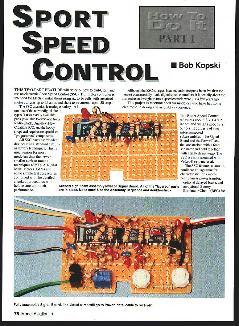
This two-part feature describes how to build, test, and use an electronic Sport Speed Control (SSC). This motor controller is intended for electric installations using six to 16 cells, with sustained motor currents up to 35 amps and short-term currents up to 50 amps. The SSC uses classic analog circuitry — not the newer digital types. It uses readily available parts (Radio Shack, Digi-Key, New Creations R/C, and hobby shops) and requires no special or programmed components.
All SSC parts are leaded devices using standard circuit-assembly techniques. This is much easier for most modelers than the smaller surface-mount techniques (SMT). A digital multimeter (DMM) and some simple test accessories combined with the detailed checkout procedures will help assure top-notch performance.
Although the SSC is larger, heavier, and more parts-intensive than the newest commercially made digital speed controllers, it is about the same size and weight as most speed controls were a few years ago. This project is recommended for modelers who have had some electronic soldering and assembly experience.
The Sport Speed Control measures about 0.8 x 1.4 x 2.1 inches and weighs about 2.2 ounces. It consists of two interconnected subassemblies — the Signal Board and the Power Plate — that are stacked with a foam separator and held together with heat-shrink wrap. The SSC is easily mounted with Velcro strip material.
Features include:
- Smooth, nonlinear voltage transfer characteristic for a more nearly linear power transfer.
- Optional delayed brake.
- Optional Battery Eliminator Circuit (BEC) for use up to 12 cells.
- Easy, minimally interactive "two screw" tuneup to match stick throw on your transmitter.
- "Glitch free" upon motor/receiver power-up provided the throttle stick is in the off position.
- Efficient high-rate design.
- Optional adjustable motor cutoff to prevent deep-discharging of the motor battery.
The motor cutoff is useful whether you use the BEC or not, and for any number of cells within the design range. It can extend motor battery cycle life in some cases.
The Signal Board uses a preprinted hole board—no PCB layout and etching needed. Most components are mounted on this board.
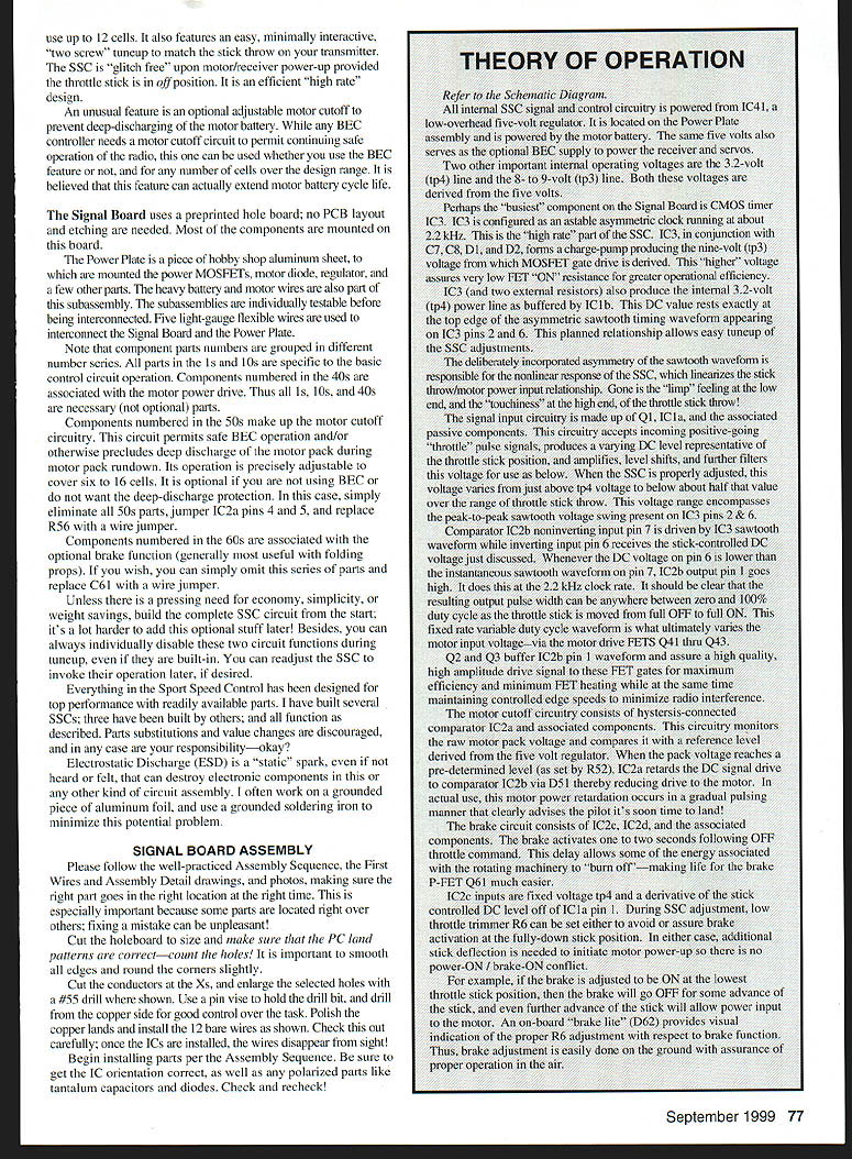
The Power Plate is a piece of hobby-shop aluminum sheet to which the power MOSFETs, motor diode, regulator, and a few other parts are mounted. Heavy battery and motor wires are part of this subassembly. The subassemblies are individually testable before interconnection. Five light-gauge flexible wires interconnect the Signal Board and the Power Plate.
Component grouping notes:
- Parts in the 1s and 10s are specific to basic control circuit operation.
- Components numbered in the 40s are associated with the motor power drive.
- Components in the 50s make up the motor cutoff circuitry. This circuit permits safe BEC operation and/or prevents deep discharge of the motor pack during rundown. It is optional. To omit: eliminate all 50s parts, jumper IC2a pins 4 and 5, and replace R56 with a wire jumper.
- Components in the 60s are associated with the optional brake function (generally useful with folding props). To omit: omit the 60s parts and replace C61 with a wire jumper.
Unless you need economy, simplicity, or weight savings, build the complete SSC circuit from the start; it is harder to add optional functions later. You can always disable them during tuneup even if built-in, and re-enable later if desired.
Everything in the SSC has been designed for top performance with readily available parts. Several SSCs have been built and tested; parts substitutions and value changes are discouraged and are your responsibility.
Electrostatic discharge (ESD) is a static spark that can destroy electronic components. Minimize this problem by working on grounded aluminum foil and using a grounded soldering iron.
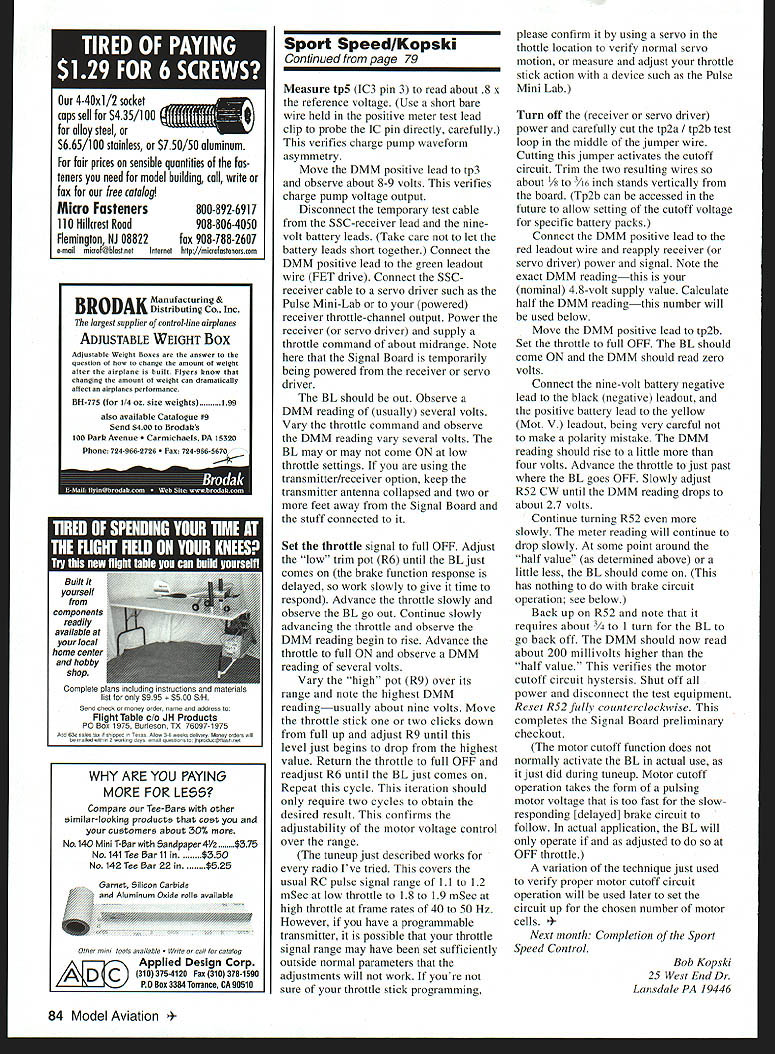
Signal Board Assembly
Please follow the Assembly Sequence, the First Wires and Assembly Detail drawings, and photos, ensuring the right part goes in the right location at the right time. Some parts lie over others; fixing a mistake can be unpleasant.
Assembly preparatory steps:
- Cut the holeboard to size and make sure the PC land patterns are correct—count the holes.
- Smooth all edges and round the corners slightly.
- Cut the conductors at the Xs and enlarge selected holes with a #55 drill where shown. Use a pin vise and drill from the copper side for good control.
- Polish the copper lands and install the 12 bare wires as shown. Check carefully; once the ICs are installed the wires disappear from sight.
Begin installing parts per the Assembly Sequence. Be sure of IC orientation and polarized parts (tantalum capacitors, diodes). Check and recheck.
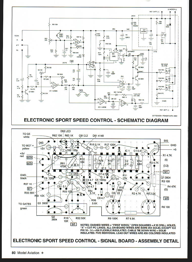
Theory of Operation
Refer to the schematic diagram. All internal SSC signal and control circuitry is powered from IC41, a low-overhead five-volt regulator located on the Power Plate and powered by the motor battery. The same five volts also serves as the optional BEC supply for the receiver and servos.
Two other important internal operating voltages are the 3.2-volt (tp4) line and the 8–9-volt (tp3) line. Both are derived from the five volts.
The primary timing component on the Signal Board is CMOS timer IC3, configured as an astable asymmetric clock running at about 22 kHz. This is the "high rate" part of the SSC. IC3, with C7, C8, D1, and D2, forms a charge pump producing the tp3 voltage from which the MOSFET gate drive is derived. This higher voltage assures very low FET ON resistance for greater efficiency.
IC3 (with two external resistors) also produces the internal 3.2-volt (tp4) power line as buffered by IC1b. This DC value sits near the top edge of the asymmetric sawtooth timing waveform on IC3 pins 2 and 6. This planned relationship allows easy tuneup of the SSC adjustments.
The deliberate asymmetry of the sawtooth waveform creates the nonlinear response of the SSC, which linearizes the stick-throw-to-motor-power relationship. This removes limp feeling at low end and excessive punchiness at the high end.
Signal input circuitry consists of Q1, IC1a, and associated components. It accepts incoming positive-going throttle pulse signals, produces a varying DC level representative of throttle stick position, amplifies and level-shifts this voltage, and filters it for use by the comparators. When properly adjusted, this voltage varies from just above tp4 to below about half that value across the throttle range. This range encompasses the peak-to-peak sawtooth voltage on IC3 pins 2 & 6.
Comparator IC2b noninverting input (pin 5) is driven by the IC3 sawtooth waveform while the inverting input (pin 6) receives the stick-controlled DC voltage. Whenever the DC voltage on pin 6 is lower than the instantaneous sawtooth level on pin 5, IC2b output (pin 1) goes high at the 2.2 kHz clock rate. The resulting output pulse width varies from zero to 100% duty cycle as the throttle stick moves from OFF to ON. This fixed-rate variable duty cycle waveform ultimately varies motor input voltage via the motor drive FETs Q4–Q6 (labeling varies by implementation).
Q2 and Q3 buffer IC2b pin 1 waveform and provide a high-amplitude drive signal to the FET gates for maximum efficiency and minimum FET heating while controlling edge speeds to minimize radio interference.
The motor cutoff circuitry is hysteresis-connected comparator IC2a and associated components. It monitors raw motor pack voltage and compares it with a reference derived from the five-volt regulator. When pack voltage reaches a preset level (set by R52), IC2a retards the DC drive to IC2b via D5, reducing motor drive. In practice, motor power is reduced in a gradual pulsing manner, alerting the pilot that it is time to land.
The brake circuit consists of IC2c, IC2d, and associated components. The brake activates one to two seconds after an OFF throttle command. The delay allows energy associated with rotating machinery to burn off, making life easier for the brake P-FET Q11.
IC2c inputs are fixed voltage tp4 and a derivative of the stick-controlled DC level from IC1a pin 1. During SSC adjustment, low-throttle trim R6 can be set to avoid or assure brake activation at the fully-down stick position. In either case, additional stick deflection is required to initiate motor power-up so there is no power-ON / brake-OFF conflict.
For example, if the brake is set ON at the lowest stick position, the brake will go OFF for some advance of the stick, and further advance will allow motor power. An onboard brake indicator (D62) provides visual indication of proper R6 adjustment relative to brake function. Brake adjustment is easily done on the ground with assurance of proper in-air operation.
Signal Board Assembly Sequence
- Cut board to outline, notch, and sand edges smooth.
- Cut conductors at the 10 "X" locations.
- Enlarge 13 "open square" holes with a #55 bit; polish copper lands.
- Install 12 #24 wires flat on the board; solder only at the "solid dots."
- Set in place 3 ICs; trim package flash for easy end-to-end fit as required.
- Install R14 (3.6K) & R16 (10K); solder, making sure ICs are flush on the board.
- Install R12 (18K) and D51 (1N4148); locate diode as high as resistors; solder.
- Install C9 & C62 (both 100 pF); solder.
- Install R61 (470K); install IC2 pins 10–14, and a bare wire to IC2 pin 8; solder.
- Install R11 (27K) & R13 (2.0K); solder.
- Install C2 (2.2 µF) & C7 (4.7 µF); solder.
- Install D62 (LED); note the flat at the cathode end; solder cathode lead only.
- Install D61 (1N4148) and R63 (1K); note bottom R61 wire extends over to D62 anode under board; solder.
- Solder all remaining IC pin locations.
- Pause — this completes the "stacked" part of the assembly; reaffirm all work to here before proceeding.
- Install Q1 (2N3904) and Q2 (2N3904); solder.
- Install Q3 (2N3906) and associated wire; solder.
- Install C51 (0.1 µF); solder.
- Install R6 (100 ohm pot) & R7 (6.8K); solder.
- Install R9 (100K pot); solder.
- Install R52 (50K pot); solder.
- Install D63 (1N5242) and R62 (10K); solder.
- Install R15 (5.1K) & R17 (120K); solder.
- Install R54 (5.1K) & R57 (1.0K); solder.
- Install R55 (56K) & R56 (5.6K); solder.
- Install D1 & D2 (both SD103ACT); solder.
- Install R53 (12K) & associated wire. Dress top resistor wire close to body; solder.
- Install C3 & C4 (both 4.7 µF); solder.
- Install C61 (2.2 µF) and C1 (0.47 µF); solder.
- Install R1 & R2 (both 4.7K); solder.
- Install R3 (4.7K) and R4 (47K); solder.
- Install R8 (2.2K), dressing top lead under R6 body; solder.
- Install R5 (100 ohms) & R10 (68K), shaping top lead of latter as required; solder.
- Install C5 (1000 pF) and associated wire; solder.
- Install C6 (22 µF) and C8 (47 µF); solder.
- Install R18 (10K) & R51 (15K); solder.
- Install remaining bare wire jumpers; solder as appropriate.
- Install SSC-receiver cable (piece of aileron extension) with strain-relief loop-through; solder.
- Install five flexible six-inch-long colored wires as shown; solder.
- Trim all leads flush with the bottom of the board.
- Lightly block-sand the bottom of the board, 180–220 grit.
- Solvent-clean the bottom of the board.
- Inspect assembly, touch up solder as needed, re-solder, clean, and reinspect as required.
- Strip and tin five flying leads in preparation for test.
Assembly tips:
- Keep components low on the board unless noted, but allow some wire lead between the board and the part.
- Do not damage parts by bending leads sharply near component bodies.
- Do not solder a location until all component leads are in place.
- You may nip component leads after any solder step.
- Some wire jumpers are shaped as loops to clear components or to serve as test points—install these loops as depicted.
- Use a sewing needle in a pin vise to probe crowded holes to ease insertion.
- Cut component leads on an angle to help insertion in crowded holes.
- Ensure solder results in a bright, shiny solder cone completely surrounding leads and lands; no cold joints or gaps.
- Clean the conductor side with an acid brush and solvent (e.g., acetone); brush from underneath, allowing solvent to drip away from the assembly.
- Inspect with a lens for questionable joints, land-to-land shorts, and tiny whiskers.
- Nip off any remaining lead stubs and block-sand the bottom of the board. Leveling ensures no wire projections interfere with the foam separator and Power Plate.
- Reclean with solvent as needed and reinspect.
- Don’t be reluctant to rework—often two or three passes are required to get everything right.
- Ensure all top-side leads are properly dressed and do not touch each other.
Assembly Diagrams and Notes
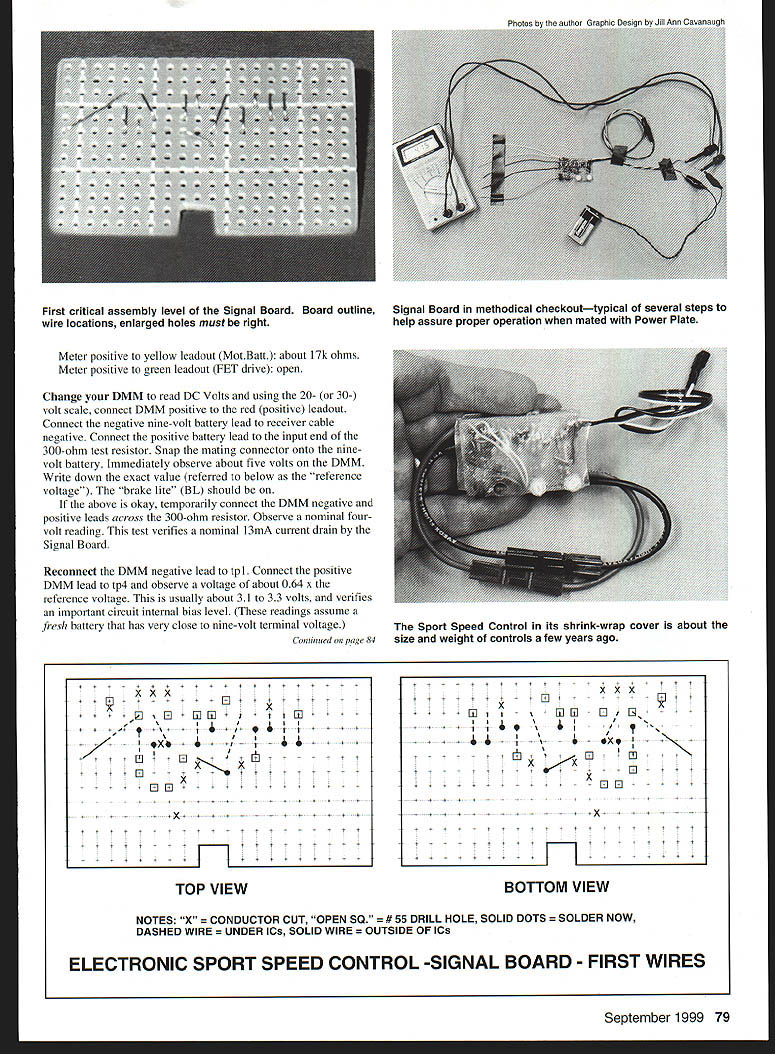
Top view / Bottom view diagrams referenced in the original documentation indicate:
- "X" = conductor cut.
- "OPEN SQ." = #55 drill hole.
- "SOLID DOTS" = solder now.
- "DASHED WIRE" = under ICs.
- "SOLID WIRE" = outside of ICs.
First-wires and assembly detail notes:
- Dashed wires = "first wires".
- Open squares = #55 drill holes.
- "X" = cut PC lands.
- All on-board wires are bare #24 solid, except IC2 pin 10–14 = #26 flexible insulated.
- Cable tie-down wire = solid insulated.
- Five individual lead-out wires are #26 colored insulated.
Signal Board Checkout and Preliminary Tuneup
These tests check Signal Board operation so that when the Signal Board and Power Plate are combined you will likely have immediate, safe, proper operation of the SSC.
Required items:
- DMM
- Fresh nine-volt alkaline battery and matching battery snap connector with small test clips
- 300-ohm resistor
- Test leads with micro or mini test clips for the DMM
- The cutoff portion of the aileron extension (the other half is the SSC-receiver cable)
- Your transmitter and operating receiver, or a calibrated servo driver (e.g., Pulse Mini Lab)
Perform tests methodically in the order given. Troubleshoot and fix any unexpected results before proceeding.
Signal Board setup:
- Place the Signal Board component-side up on a clean, nonconducting surface.
- Hold the five leadout wires spread apart with tape.
- Strip and tin the aileron-cable cutoff ends, and solder a 300-ohm resistor to the positive lead.
- Connect this accessory cable to the SSC-receiver cable and tape the stub to the work surface.
Initial pot settings:
- Set R6 ("low") and R9 ("high") pots to about midrange.
- Set R52 fully counterclockwise (it will click at the end of its range).
With the DMM on ohms (range accordingly), measure (DMM negative lead to tp1 unless stated otherwise):
- Receiver cable negative to positive: about 2.3k ohms.
- Receiver cable negative to signal: open (very high ohms).
- Receiver cable positive to signal: open.
- Receiver cable positive to red (positive) leadout wire: short (fraction of an ohm).
- Receiver cable negative to black (negative) leadout wire: short.
- Receiver cable negative to tp1 (test loop on board): short.
Additional resistance checks:
- Meter position white leadout (Q5 drive): open.
- Meter positive to yellow leadout (Mot. Batt.): about 17k ohms.
- Meter positive to green leadout (FET drive): open.
Voltage checks:
- Switch the DMM to DC volts (20- or 30-volt scale). Connect DMM positive to the red leadout. Connect the DMM negative to receiver-cable negative. Connect the positive battery lead to the input end of the 300-ohm resistor and snap the connector to the nine-volt battery. Immediately observe about five volts on the DMM. Record the exact value (the "reference voltage"). The brake light (BL) should be on.
- With the DMM leads across the 300-ohm resistor, observe nominally 4 volts. This verifies roughly 13 mA current drain by the Signal Board.
- Reconnect the DMM negative to tp1. Connect DMM positive to tp4 and observe about 0.64 × reference voltage (usually about 3.1–3.3 V). This verifies an important internal bias level. (These assume a fresh nine-volt battery.)
- Measure tp5 (IC3 pin 3) to read about 0.8 × reference voltage. Use a short bare wire in the positive meter clip to probe the IC pin directly, carefully. This verifies charge pump waveform asymmetry.
- Move DMM positive to tp3 and observe about 8–9 volts. This verifies the charge pump output.
Receiver/servo powered checks:
- Disconnect the temporary test cable from the SSC-receiver lead and the nine-volt battery leads.
- Connect DMM positive to the green leadout (FET drive).
- Connect the SSC-receiver cable to a servo driver or to your powered receiver throttle-channel output. Power the receiver (or servo driver) and command about midrange throttle. Note the Signal Board is temporarily powered from the receiver or servo driver.
Observations:
- The BL should be off.
- The DMM should read several volts on the green leadout; vary the throttle and observe the reading vary.
- The BL may or may not come on at low throttle settings.
- Keep the transmitter antenna collapsed and two or more feet away from the Signal Board and connected components.
Tuneup procedure:
- Set throttle to full OFF. Adjust R6 (low trim) until the BL just comes on (work slowly; brake response is delayed).
- Advance throttle slowly and observe BL go out. Continue advancing and observe the DMM reading begin to rise. Advance to full ON and observe several volts on the DMM.
- Vary the high pot R9 over its range and note the highest DMM reading—usually about nine volts. Move the throttle one or two clicks down from full and adjust R9 until this level just begins to drop from the highest value.
- Return throttle to full OFF and readjust R6 until the BL just comes on. Repeat this cycle. Two iterations should obtain the desired result.
Notes:
- The tuneup works for typical RC pulse ranges of ~1.1–1.2 ms at low throttle to ~1.8–1.9 ms at high throttle at 40–50 Hz frame rates. If you have a programmable transmitter with an unusual throttle range, confirm normal throttle operation using a servo or a device such as the Pulse Mini‑Lab.
Cutting test loop to activate cutoff:
- Turn off receiver/servo power and carefully cut the tp2a/tp2b test loop in the middle of the jumper wire. Cutting this jumper activates the cutoff circuit.
- Trim the two resulting wires so about 1/8–3/16 inch stands vertically from the board. (Tp2b can be accessed later to set cutoff voltage for specific battery packs.)
- Connect DMM positive to the red leadout wire and reapply receiver/servo power and signal. Note the exact DMM reading—this is your nominal 4.8‑volt supply value. Calculate half the DMM reading; this will be used below.
Cutoff adjustment:
- Move DMM positive to tp2b. Set throttle to full OFF. BL should come ON and the DMM should read zero volts.
- Connect the nine-volt battery negative to the black (negative) leadout, and the positive battery lead to the yellow (Mot. V.) leadout—be very careful not to reverse polarity. The DMM reading should rise to a little more than four volts.
- Advance the throttle just past where the BL goes off. Slowly adjust R52 clockwise until the DMM reading drops to about 2.7 volts.
- Continue turning R52 very slowly. Meter reading will continue to drop; around the previously calculated half value (or a little less) the BL should come on. Back off R52 and note it requires about 3/4 to 1 turn for the BL to go back off; the DMM should then read about 200 mV higher than the half value. This verifies the motor cutoff circuit hysteresis.
- Shut off all power and disconnect test equipment. Reset R52 fully counterclockwise.
Note: During normal operation the motor cutoff function usually pulses motor voltage too fast for the slow, delayed brake to follow; the BL will only operate if and as adjusted at OFF throttle.
A variation of this technique will be used later to set the cutoff for the chosen number of motor cells.
Next Month
Completion of the Sport Speed Control.
Bob Kopski 25 West End Dr. Lansdale, PA 19446
Transcribed from original scans by AI. Minor OCR errors may remain.

