
Sport Utility Twin
BY JIM FELDMANN
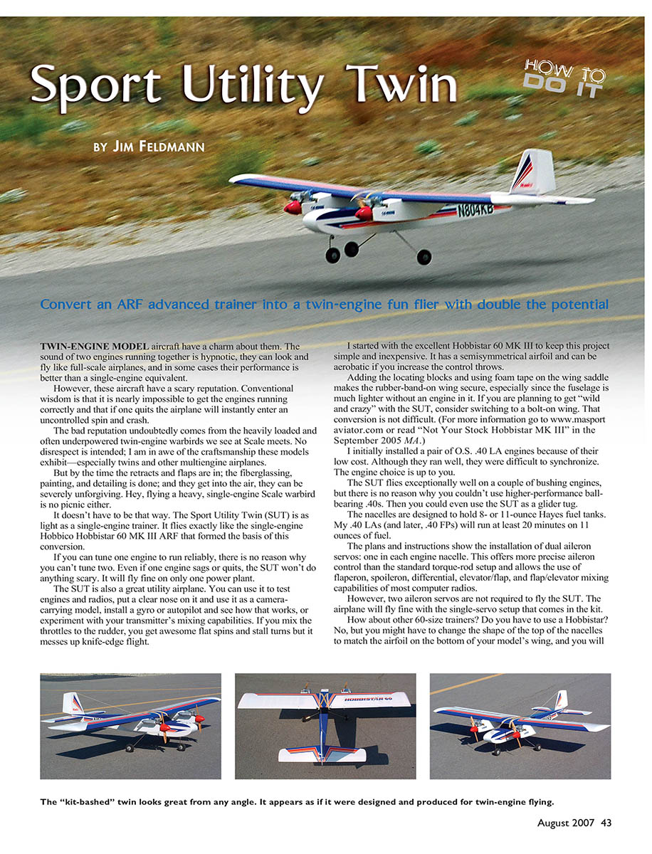
Convert an ARF advanced trainer into a twin-engine fun flier with double the potential.
TWIN-ENGINE model aircraft have a charm about them. The sound of two engines running together is hypnotic, they can look and fly like full-scale airplanes, and in some cases their performance is better than a single-engine equivalent.
However, these aircraft have a scary reputation. Conventional wisdom is that it is nearly impossible to get the engines running correctly and that if one quits the airplane it will instantly enter an uncontrolled spin and crash.
The bad reputation undoubtedly comes from the heavily loaded and often underpowered twin-engine warbirds we see at Scale meets. No disrespect is intended; I am in awe of the craftsmanship these models exhibit—especially twins and other multiengine airplanes. But by the time the retracts and flaps are in; the fiberglassing, painting, and detailing is done; and they get into the air, they can be severely unforgiving. Hey, flying a heavy, single-engine Scale warbird is no picnic either.
It doesn't have to be that way. The Sport Utility Twin (SUT) is as light as a single-engine trainer. It flies exactly like the single-engine Hobbico Hobbistar 60 MK III ARF that formed the basis of this conversion.
If you can tune one engine to run reliably, there is no reason why you can't tune two. Even if one engine sags or quits, the SUT won't do anything scary. It will fly fine on only one power plant.
The SUT is also a great utility airplane. You can use it to test engines and radios, put a clear nose on it and use it as a camera-carrying model, install a gyro or autopilot and see how that works, or experiment with your transmitter's mixing capabilities. If you mix the throttles to the rudder, you get awesome flat spins and stall turns but it messes up knife-edge flight.
I started with the excellent Hobbistar 60 MK III to keep this project simple and inexpensive. It has a semisymmetrical airfoil and can be aerobatic if you increase the control throws.
Adding the locating blocks and using foam tape on the wing saddle makes the rubber-band-on wing secure, especially since the fuselage is much lighter without an engine in it. If you are planning to get "wild and crazy" with the SUT, consider switching to a bolt-on wing. That conversion is not difficult. (For more information go to www.masportaviator.com or read "Not Your Stock Hobbistar MK III" in the September 2005 MA.)
I initially installed a pair of O.S. .40 LA engines because of their low cost. Although they ran well, they were difficult to synchronize. The engine choice is up to you.
The SUT flies exceptionally well on a couple of bushing engines, but there is no reason why you couldn't use higher-performance ball-bearing .40s. Then you could even use the SUT as a glider tug.
The nacelles are designed to hold 8- or 11-ounce Hayes fuel tanks. My .40 LAs (and later, .40 FPs) will run at least 20 minutes on 11 ounces of fuel.
The plans and instructions show the installation of dual aileron servos: one in each engine nacelle. This offers more precise aileron control than the standard torque-rod setup and allows the use of flaperon, spoileron, differential, elevator/flap, and flap/elevator mixing capabilities of most computer radios. However, two aileron servos are not required to fly the SUT. The airplane will fly fine with the single-servo setup that comes in the kit.
How about other 60-size trainers? Do you have to use a Hobbistar? No, but you might have to change the shape of the top of the nacelles to match the airfoil on the bottom of your model's wing, and you will need to check the wing incidence and downthrust to make sure the final angle of the twin firewalls will match the angle of the stock firewall in your kit.
Complete all the following steps before you start the assembly instructions that come with the kit. The first thing you need to do is open the kit and become familiar with its parts and pieces. Read through the assembly instructions and then set them aside.
Remove any taped-on control surfaces. Clean off the tape residue with mineral spirits (paint thinner) and remove the covering from the rudder. For all the rest of the parts use a covering iron to seal the edges of the trim and the joints where the covering overlaps. Use a heat gun and the iron to eliminate any wrinkles or bubbles, and firmly iron the rest of the covering to the wood.
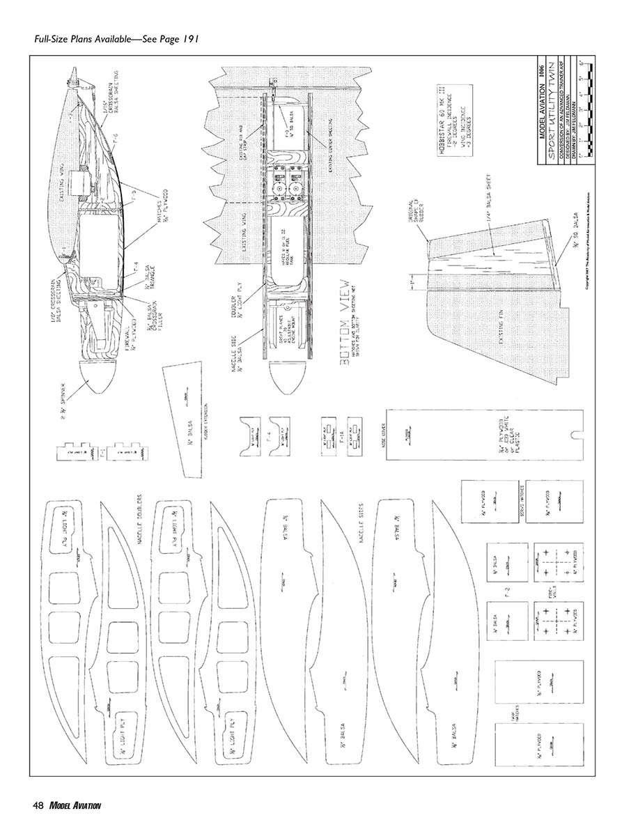
Cut the parts templates from the SUT plans sheet. Lightly spray 3M Super 77 spray adhesive on the back of the templates and let it dry for roughly a minute. Stick the templates to your wood. Cut out all the new parts that are required.
Modifying the Rudder
Twins need more rudder authority than single-engine airplanes because there is no propeller blast over its surface. The following steps will approximately double the rudder’s size and effectiveness.
- Cut the kit’s rudder in two parts 1 inch behind its leading edge. This will allow you to use the original hinge slots.
- Glue the 1/4-inch balsa rudder insert between the two pieces of the original rudder, and add the new bottom piece.
- Sand the outline to shape as shown on the plans and sand both sides smooth. Round off the top of the rudder to match the top of the fin.
Assembling the Nacelles
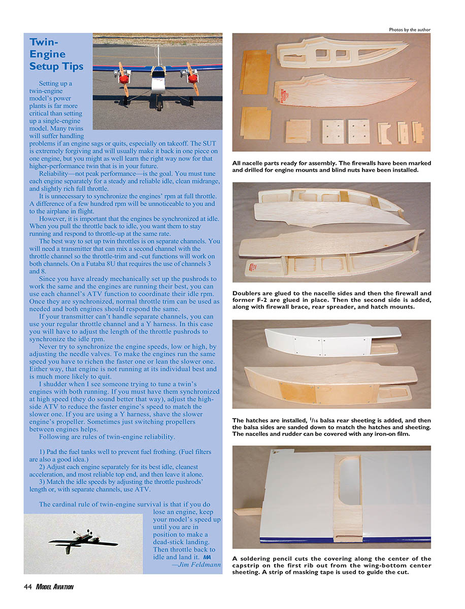
- Mark the firewalls’ centerlines as shown on the plans. Use the templates that come with the Great Planes engine mounts to center, mark, and drill the engine-mount holes. Install the blind nuts and hold them in place with a bit of thin cyanoacrylate.
- Mark the position of the firewall and former F-2 on the inside of the light-plywood doublers. Use slow-drying cyanoacrylate to attach the light-plywood doublers to the 1/8-inch balsa sheeting. Make two left sides and two right sides.
- Trim the edges of the balsa sides to match the doublers. Leave 1/8 inch of balsa protruding past the bottom of the doubler between the firewall and the rear end of the nacelle.
- Sand the top and bottom of the firewall to the approximate angles shown on the plans, and then glue the firewall and former F-2 to one side of each nacelle. Use a triangle to ensure they are 90° to each nacelle side. Add the second side to each nacelle.
- Recheck to make sure everything is square. Add the light-plywood firewall brace (F-4), the 1/4 square balsa rear spreader (F-3), and the hatch mounts (F-5 and F-6).
- Glue 1/4 balsa triangle reinforcements behind the sides of the firewalls, then add the nacelle bottoms and the wing-saddle doubler.
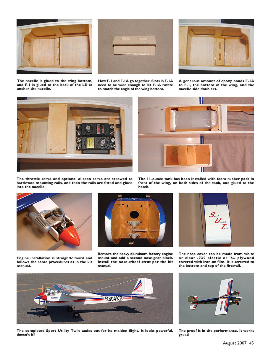
- Glue the sides of the nacelles to the bottom and use the plan view to locate and glue the nacelle to the bottom of the wing. The nacelle is glued to the wing bottom, and F-1 is glued to the back of the leading edge to anchor the nacelle.
- Add the hatch doubler and slot the hatch using a razor blade so it can be glued to the wing and removed for servicing. The nacelle hatch should have a 3/32-inch plywood doubler glued to the inside of the hatch in the area the gas tank will rest.
- If you are installing the optional aileron servo in the nacelle, install the mounting rails now and upgrade the vented hatch to allow access to the servo.
- Cut and fit the nacelle top and fillet the seams. Fit the nacelle fill pieces and sand the seams smooth. Fit the nacelle cowl or nose block to the nacelle and sand to shape. If you are using the plywood cowl ring, check for symmetry and fillet the edges.
- Use finishing resin or thinned epoxy to coat the engine bay and the fuel-tank area of the nacelles to protect them from fuel residue. Cover the inside of the hatches too, and make sure the fuel-proofing overlaps and seals the covering's edges.
After the 1/16 balsa front filler is installed, install the 1/16 plywood tank hatch and servo hatch, then fit and glue on the 1/16 balsa rear sheeting. Once the 1/8 balsa top sheeting is glued in place, sand the bottom of the balsa nacelle sides to match the installed hatches and the rear sheeting. Round all the edges to roughly match the radius of the fuselage corners. Do not round the edge of the nacelle where it will attach to the wing. Cover the nacelles and the hatches with matching or contrasting iron-on covering. Cover the modified rudder and the nose cover (if required).
Attaching the Nacelles to the Wings
- Turn one wing upside down and work on the bottom. You can do one wing at a time or both simultaneously.
- Locate the first rib out from the center sheeting and cut the covering material in the middle of the capstrip over that rib. Make the cut from the center of the leading edge back to 1/2 inch from the wing trailing edge. Run a piece of masking tape along the wing as a guide for the cut.
- I like to use a pencil-type soldering iron to burn through the covering. Do not use a blade that could cut into the wood.
- Hold a nacelle up against the wing with the outer edge just covering the burned edge of the covering. Draw a line on the wing along the inner edge of the nacelle. Use the soldering pencil to cut the covering 1/16 inch inside the line and across the front and rear. Remove the covering inside the cut lines.
- The covering in the next bay out will wrinkle slightly; do not reshrink it yet. Doing so could bend the rib and cause the covering to pull away from the capstrip. You can reshrink the covering after the nacelle is glued on.
- Cut a slot through the exposed sheeting at the rear of the solid-wood leading edge so F-1 can be glued in later. Make the slot at least 3/16 inch wide.
- Hold the nacelle against the wing with the top sheeting against the leading edge, and run thin cyanoacrylate along the joint. Follow immediately with thick cyanoacrylate to fill any minor gaps. If all gaps are filled, the cyanoacrylate's strength is more than adequate and much easier than epoxy.
- Fit F-1 into the slot. You will probably have to shorten it slightly on the inner side and then glue it firmly to the back of the leading edge. Mix a batch of slow-cure epoxy and glue F-1A on top of F-1. Be sure to firmly glue F-1A to the nacelle side doublers as well.
Installing the Servos
- Mount the throttle and (optional) aileron servos to their 3/8-inch square hardwood mounts, sand the mounts to the right length, and glue them in place as shown on the plans.
- Run the servo wires out through the existing holes in the ribs and the kit's aileron servo hole in the bottom center sheeting.
- If you are using dual aileron servos, cut off the metal torque rods that are factory installed in the wings and attach the ailerons to the wing using the hinges provided in the kit.
- Install the aileron horn in line with the aileron servo arm.
- Line up the pushrod and drill a 1/8-inch-diameter hole through the rear sheeting of the nacelle where the pushrod will pass through. Use the kit-provided aileron pushrods, clevises, and snap connectors, and enlarge the hole as needed for clearance.
Mounting the Engines
- Drill two 1/4-inch-diameter holes near the center of each firewall for the fuel lines. Drill a 1/8-inch-diameter hole for the throttle pushrod that is tight against the right-side doubler, 1-1/4 inches down from the top of the firewall.
- Position the engines on their mounts with the back of the spinner 4 inches from the back of each mount. Screw the mounts to the firewalls.
- Install a selection of plastic tubing from the firewall through former F-2. Make a Z bend in the end of the throttle pushrod, attach it to the engine's throttle arm, and run it through the tube back to the servo arm. This will take some creative bending; you can curve the second pushrod to match the first so you don't have to do it twice.
- Use one of the kit-provided adjustable pushrod connectors to attach the pushrod to the servo arm.
- Hook the two throttle servos up to your radio and adjust the pushrods so the carburetor barrels begin to open at the same point on the throttle stick. This is critical if you will use a single channel to work both throttles and gives a good starting point even if you will use two separate channels.
- Install each servo hatch cover with four #2 x 1/4-inch sheet-metal screws.
Installing the Fuel Tanks
- Assemble the fuel tanks and pad them well with 1/8-inch-thick foam wing-saddle tape in the areas where they might touch wood. Add a foam pad inside the nacelle over F-1A.
- Attach fuel lines and install the tanks. Add foam on both sides of the tank and between the tank and the hatch. Do not skip the foam tape and padding. If the tank touches any wood, fuel frothing is likely and you will never get the engines to run consistently.
- Connect the fuel lines to your engines and install the fuel-tank hatch covers with #2 x 1/4-inch sheet-metal screws.
- Use thin CA to hold the tank in position while the epoxy sets.
Installing the Nose Cover
- The nose cover can be made from plywood and covered with iron-on film or made from white or clear plastic. If it is plastic, use a fiberglass reinforcement at the top and bottom ends to prevent cracking around the mounting screws.
- Remove the heavy aluminum factory engine mount that comes with the kit; you won't need it. Add a second nylon nose-gear block 1 inch above the one at the bottom of the firewall. The necessary screws and blind nuts come with the block.
- Install the nose-wheel strut, steering arm, and wheel collars as shown in the kit instructions. Do not shorten the steering arm as shown in the kit; that would make the steering far too sensitive.
- Instead, drill a new hole through the firewall for the steering pushrod. This hole should be aligned with the existing outer hole of the steering arm.
- Fit the notched end of the nose cover over the nose-gear strut and use a #2 x 1/4-inch sheet-metal screw to attach it to one corner of the bottom of the firewall. Wrap the cover tightly over the nose and use three screws to attach it to the top of the firewall. Go back and attach the other side of the bottom with the last screw.
Adding the Tail Skid
With the wing removed the SUT fuselage will drop down onto its tail. To protect the tail end of the fuselage from gravel rash, drill the two required holes and glue in a nylon wingtip skid.
Installing the Wing-Locating Blocks
- Join the wings by following the kit instructions. Use plenty of epoxy on the dihedral joiner.
- If you are using engines that are at the top of the power range and are planning to get wild and crazy with the SUT, you may want to fiberglass this wing center joint. That should be unnecessary in normal use.
- Cut a piece of one of the 1/4 x 1/2 balsa sticks provided in the kit to fit across the inside of the fuselage, approximately 1/2 inch behind the front of the wing saddle. Cut another piece to fit across roughly 1/2 inch in front of the rear of the wing saddle. These locating blocks will prevent the wing from shifting under load and allowing the propellers to hit the side of the fuselage.
- Carefully mark the center of each block and cut 80% of the way through at the mark so the block will bend to match the wing's dihedral.
- Position the blocks on the bottom of the wing approximately 1/2 inch from the leading edge and trailing edge, with the center marks over the wing joint, and draw around them with a pencil. Remove the covering from under the pieces and then glue them in place with thick cyanoacrylate.
You have just created a Sport Utility Twin ARF! Go ahead and assemble it using the kit instructions as needed.
- The CG and control throws will be the same as the kit’s except that you will need more rudder travel. I set up the rudder with the pushrod in the outer hole of the control horn and the standard servo arm.
Good luck and have fun!
Jim Feldmann [email protected]
Twin-Engine Setup Tips
Setting up a twin-engine model's power plants is far more critical than setting up a single-engine model. Many twins will suffer handling problems if an engine sags or quits, especially on takeoff. The SUT is extremely forgiving and will usually make it back in one piece on one engine, but you might as well learn the right way now for that higher-performance twin that is in your future.
Reliability—not peak performance—is the goal. You must tune each engine separately for a steady and reliable idle, clean midrange, and slightly rich full throttle.
It is unnecessary to synchronize the engines' rpm at full throttle. A difference of a few hundred rpm will be unnoticeable to you and to the airplane in flight.
However, it is important that the engines be synchronized at idle. When you pull the throttle back to idle, you want them to stay running and respond to the throttle-up at the same rate.
The best way to set up twin throttles is on separate channels. You will need a transmitter that can mix a second channel with the throttle channel so the throttle-trim and -cut functions will work on both channels. On a Futaba 8U that requires the use of channels 3 and 8.
Since you have already mechanically set up the pushrods to work the same and the engines are running their best, you can use each channel's ATV function to coordinate their idle rpm. Once they are synchronized, normal throttle trim can be used as needed and both engines should respond the same.
If your transmitter can't handle separate channels, you can use your regular throttle channel and a Y harness. In this case you will have to adjust the length of the throttle pushrods to synchronize the idle rpm.
Never try to synchronize the engine speeds, low or high, by adjusting the needle valves. To make the engines run the same speed you have to richen the faster one or lean the slower one. Either way, that engine is not running at its individual best and is much more likely to quit.
I shudder when I see someone trying to tune a twin's engines with both running. If you must have them synchronized at high speed (they do sound better that way), adjust the high-side ATV to reduce the faster engine's speed to match the slower one. If you are using a Y harness, shave the slower engine's propeller. Sometimes just switching propellers between engines helps.
Following are rules of twin-engine reliability:
- Pad the fuel tanks well to prevent fuel frothing. (Fuel filters are also a good idea.)
- Adjust each engine separately for its best idle, cleanest acceleration, and most reliable top end, and then leave it alone.
- Match the idle speeds by adjusting the throttle pushrods' length or, with separate channels, use ATV.
The cardinal rule of twin-engine survival is that if you do lose an engine, keep your model's speed up until you are in position to make a dead-stick landing. Then throttle back to idle and land it.
—Jim Feldmann
The proof is in the performance. It works great!
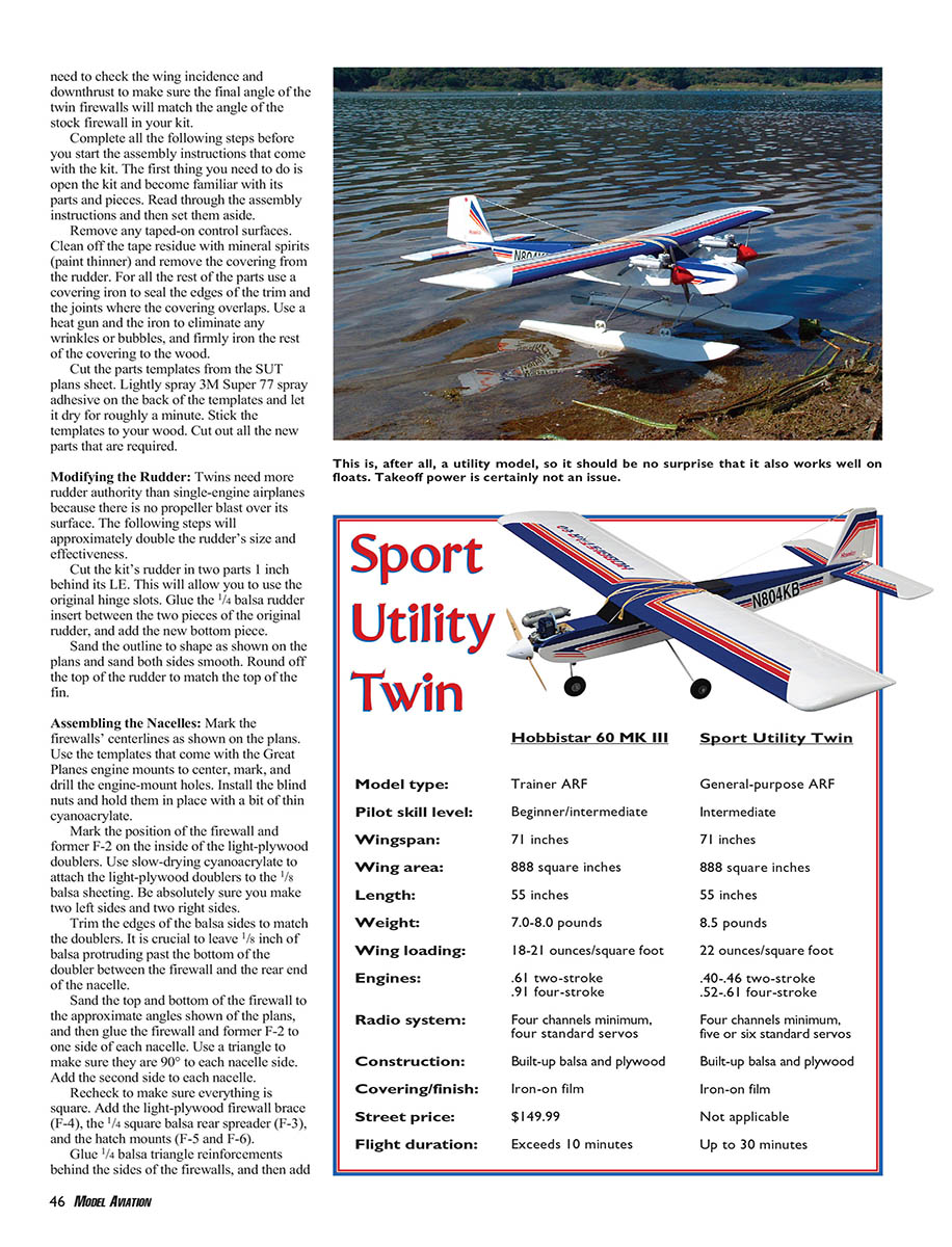
Sport Utility Twin (Specifications)
- Model type:
- Hobbistar 60 MK III: Trainer ARF
- Sport Utility Twin: General-purpose ARF
- Pilot skill level:
- Hobbistar 60 MK III: Beginner/intermediate
- Sport Utility Twin: Intermediate
- Wingspan: 71 inches (both)
- Wing area: 888 square inches (both)
- Length: 55 inches (both)
- Weight:
- Hobbistar 60 MK III: 7.0–8.0 pounds
- Sport Utility Twin: 8.5 pounds
- Wing loading:
- Hobbistar 60 MK III: 18–21 oz/sq ft
- Sport Utility Twin: 22 oz/sq ft
- Engines:
- Hobbistar 60 MK III: .61 two-stroke / .91 four-stroke
- Sport Utility Twin: .40–.46 two-stroke / .52–.61 four-stroke
- Radio system:
- Hobbistar 60 MK III: Four channels minimum, four standard servos
- Sport Utility Twin: Four channels minimum, five or six standard servos
- Construction: Built-up balsa and plywood (both)
- Covering/finish: Iron-on film (both)
- Street price:
- Hobbistar 60 MK III: $149.99
- Sport Utility Twin: Not applicable
- Flight duration:
- Hobbistar 60 MK III: Exceeds 10 minutes
- Sport Utility Twin: Up to 30 minutes
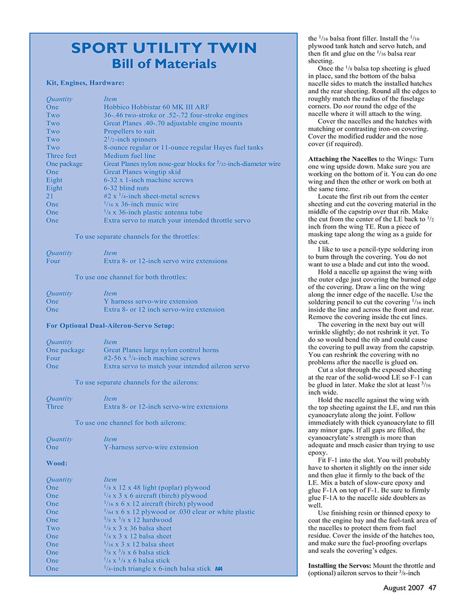
Bill of Materials
Kit, Engines, Hardware:
- One Hobbico Hobbistar 60 MK III ARF
- Two .36–.46 two-stroke or .52–.72 four-stroke engines
- Two Great Planes .40–.70 adjustable engine mounts
- Two propellers to suit
- Two 2-1/2-inch spinners
- Two 8-ounce regular or 11-ounce regular Hayes fuel tanks
- Three feet medium fuel line
- One package Great Planes nylon nose-gear blocks for 5/32-inch-diameter wire
- One Great Planes wingtip skid
- Eight 6-32 x 1-inch machine screws
- Eight 6-32 blind nuts
- 21 #2 x 1/4-inch sheet-metal screws
- One 1/16 x 36-inch music wire
- One 1/8 x 36-inch plastic antenna tube
- One extra servo to match your intended throttle servo
To use separate channels for the throttles:
- Four extra 8- or 12-inch servo wire extensions
To use one channel for both throttles:
- One Y-harness servo-wire extension
- One extra 8- or 12-inch servo-wire extension
For optional dual-aileron-servo setup:
- One package Great Planes large nylon control horns
- Four #2–56 x 3/4-inch machine screws
- One extra servo to match your intended aileron servo
To use separate channels for the ailerons:
- Three extra 8- or 12-inch servo-wire extensions
To use one channel for both ailerons:
- One Y-harness servo-wire extension
Wood:
- One 1/8 x 12 x 48 light (poplar) plywood
- One 1/4 x 3 x 6 aircraft (birch) plywood
- One 1/16 x 6 x 12 aircraft (birch) plywood
- One 1/64 x 6 x 12 plywood or .030 clear or white plastic
- One 3/8 x 3/8 x 12 hardwood
- Two 1/8 x 3 x 36 balsa sheets
- One 1/4 x 3 x 12 balsa sheet
- One 1/16 x 3 x 12 balsa sheet
- One 3/8 x 3/8 x 6 balsa stick
- One 1/4 x 1/4 x 6 balsa stick
- One 1/4-inch triangle x 6-inch balsa stick
Notes
- The nacelles are designed to hold 8- or 11-ounce Hayes tanks; my .40 engines run at least 20 minutes on 11 ounces.
- For throttle synchronization, use separate channels if possible. If not, use a Y-harness and mechanically synchronize pushrod lengths.
- Do not tune engines to the same speed by changing needle valves; tune each engine individually for reliable operation.
- Pad fuel tanks well and use fuel filters to avoid frothing.
End of article.
Transcribed from original scans by AI. Minor OCR errors may remain.

