
Spread Spectrum: Are You Ready for Full Range?
by Steve Kaluf and Dan Williams
Introduction
Roughly 18 months ago a new company introduced spread spectrum technology to the radio-control modeling world. This first system was a surface unit for use in cars and trucks. Almost exactly a year later that company debuted a six-channel aircraft radio also utilizing spread spectrum technology. That new system was limited to park-size and mini-helicopter use because of range and antenna considerations.
That unit has literally taken the park-size/mini-helicopter world by storm. Modelers using these systems no longer have to worry about frequency control and interference from outside sources. However, many of us have wondered when we would finally be able to fly our larger glow/gas aircraft with a similar system.
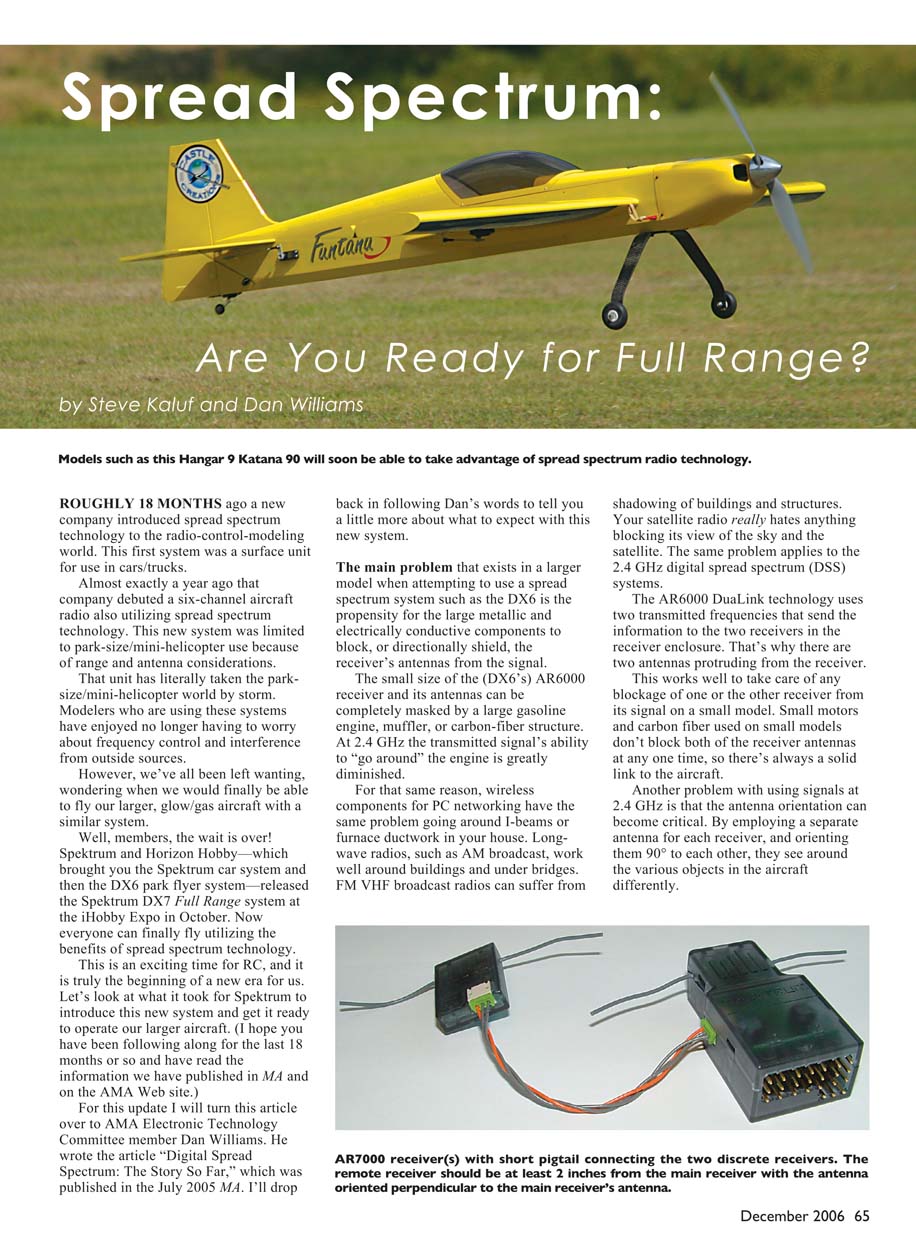
The wait is over. Spektrum and Horizon Hobby—who brought the Spektrum car system and the DX6 park flyer system—released the Spektrum DX7 Full Range system at the iHobby Expo in October. Now larger aircraft can take advantage of spread spectrum technology.
This is an exciting time for RC and the beginning of a new era. Below we explain what it took to get spread spectrum ready for larger aircraft and what to expect from the new system. For this update I turn the article over to AMA Electronic Technology Committee member Dan Williams, who wrote "Digital Spread Spectrum: The Story So Far" (July 2005 MA). I’ll return later to cover radio-system details.
The problem with larger models (Dan Williams)
The main problem when attempting to use a spread spectrum system such as the DX6 in a larger model is the propensity for large metallic and electrically conductive components to block or directionally shield the receiver's antennas from the signal.
The small size of the DX6's AR6000 receiver and its antennas can be completely masked by a large gasoline engine, muffler, or carbon-fiber structure. At 2.4 GHz the transmitted signal's ability to "go around" an engine is greatly diminished. For that same reason, wireless components for PC networking have problems going around I-beams or furnace ductwork in your house. Longwave radios, such as AM broadcast, work well around buildings and under bridges. FM VHF broadcast radios can suffer from shadowing by buildings and structures. Satellite radio requires an unobstructed view of the sky. The same problem applies to 2.4 GHz digital spread spectrum (DSS) systems.
Another issue at 2.4 GHz is that antenna orientation can become critical. By employing a separate antenna for each receiver and orienting them 90° to each other, the DX6’s DuaLink approach helps the antennas "see" around various objects in the aircraft differently. As the aircraft changes orientation during aerobatics, at least one antenna usually retains a solid link. However, as model size grows, the chance that large objects will block the signal to the tiny receiver box and antennas increases.
As model distances increase, the critical nature of antenna direction becomes worse. Large models fly farther, and the farther away the receiver is, the less signal it can receive. Those are fundamental limitations on the size of model the DX6 and AR6000 receiver can fly reliably. Regardless of reported success stories using this receiver with big models, the size of the receiver relative to the model can cause RF link problems.
From DuaLink to Full Range
The DX7 and AR7000 receivers solve these limitations. Besides the intelligence added to the DX7 transmitter, the AR7000 receiver is a total redesign of the AR6000. It still uses DuaLink technology, but it is now known as "Full Range" DuaLink technology. The receiver was developed to eliminate the problems inherent in combining the AR6000 with a large model.
The AR7000 continues to use a dual-diversity receiver design. A dual-diversity receiver processes signals from two separate receivers and uses dual antennas. The idea is to locate the two antennas some distance apart so that any blockage or other reception problem affecting one antenna won’t affect the other.
The big difference in this system is that two RF channels send information simultaneously to two receivers. Add to that the digital signal processing from both receivers, and you have a robust signal link for the dynamic environment of a model.
AR7000 architecture
The AR7000 is actually composed of two receivers connected by an umbilical cord. They can be located in different parts of the aircraft to take full advantage of dual-diversity. By placing the receivers in different positions, any blockage from, say, an engine probably won’t affect both receivers. Signal integrity is maintained and there is little to no signal loss.
Another advantage of the AR7000 is its antennas. In the AR6000 park/mini-flyer receiver, each antenna is a single "whip" style, or monopole antenna. The AR7000 utilizes two dipole wire antennas instead. A dipole antenna generally offers added gain (more signal received) and a larger "capture area"—physically, the amount of wire exposed to the RF signal. The longer the antenna, the more signal that is received.
Finally, by separating the two receivers and orienting the antennas perpendicularly (known as "orthogonal" in the RF world), all model orientations relative to the transmitter antenna are covered. No matter the attitude of the model, at least one antenna will be oriented for a good signal lock.
System details (Steve Kaluf)
Thanks to Dan for that update on the technology and what was involved to get spread spectrum ready for larger aircraft. As I mentioned earlier, we don’t expect this new technology to make 72 MHz systems disappear, but it will ease congestion at many flying sites and make flightlines more enjoyable for those using both spread spectrum and 72 MHz systems. The 72 MHz band should open up as more spread spectrum systems become available.
The new Spektrum RC system is again based on an existing JR transmitter—this time the JR 7202—so everything except the RF link is JR hardware. I had early access to this system in August 2006 and have enjoyed flying and learning with it ever since.
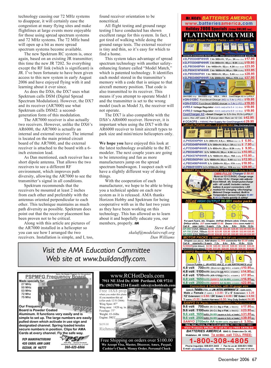
As with the DX6, the DX7 uses what Spektrum calls DSM (Digital Spread Spectrum Modulation). However, the DX7 and its AR7000 receiver use DSM2: a second-generation form of the modulation.
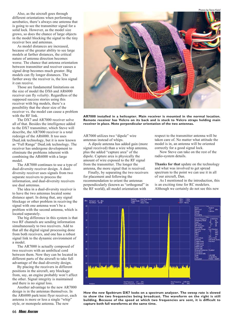
The AR7000 is actually two receivers. Unlike the DX6’s AR6000, the AR7000 has an internal receiver mounted on the main printed circuit board and an external receiver attached via a 6-inch extension lead. Each receiver has a short dipole antenna so the two receivers see different RF environments. This improves path diversity and helps the AR7000 maintain signal in all conditions.
Spektrum recommends mounting the receivers at least 2 inches apart and, preferably, with the antennas oriented perpendicular to each other. This maintains as much path diversity as possible. Spektrum also notes that receiver placement has been proven not to be critical.
I installed the AR7000 in a helicopter to test it; installation is simple and receiver orientation proved noncritical in my experience. All flight testing and ground range testing showed excellent range for this system. The external receiver is tiny and thin, so it’s easy to find a home for it.
Features and compatibility
This system also includes a safety-enhancing feature called Model Match (patented). Model Match identifies each model stored in the transmitter’s memory with a code unique to that memory position. That code is transmitted to the receiver, so if you attempt to operate Model 1 with the transmitter set to the wrong model (for example, Model 3), the receiver will not operate for safety.
The DX7 is compatible with the DX6’s AR6000 receiver. However, when using the DX7 with the AR6000, limit aircraft types to park-size and mini/micro helicopters only.
Conclusion
We hope you’ve enjoyed this look at the latest technology available to the RC modeler. The next couple of years will be interesting as more manufacturers adopt spread spectrum approaches—each likely with slightly different implementations. With manufacturer cooperation, we hope to provide technical updates on each new system as they are released.
AMA thanks Horizon Hobby and Spektrum for their cooperation over the past two years while they developed this technology. Their openness has allowed us to learn about it and help educate our members.
Steve Kaluf [email protected]
Dan Williams
Transcribed from original scans by AI. Minor OCR errors may remain.

