
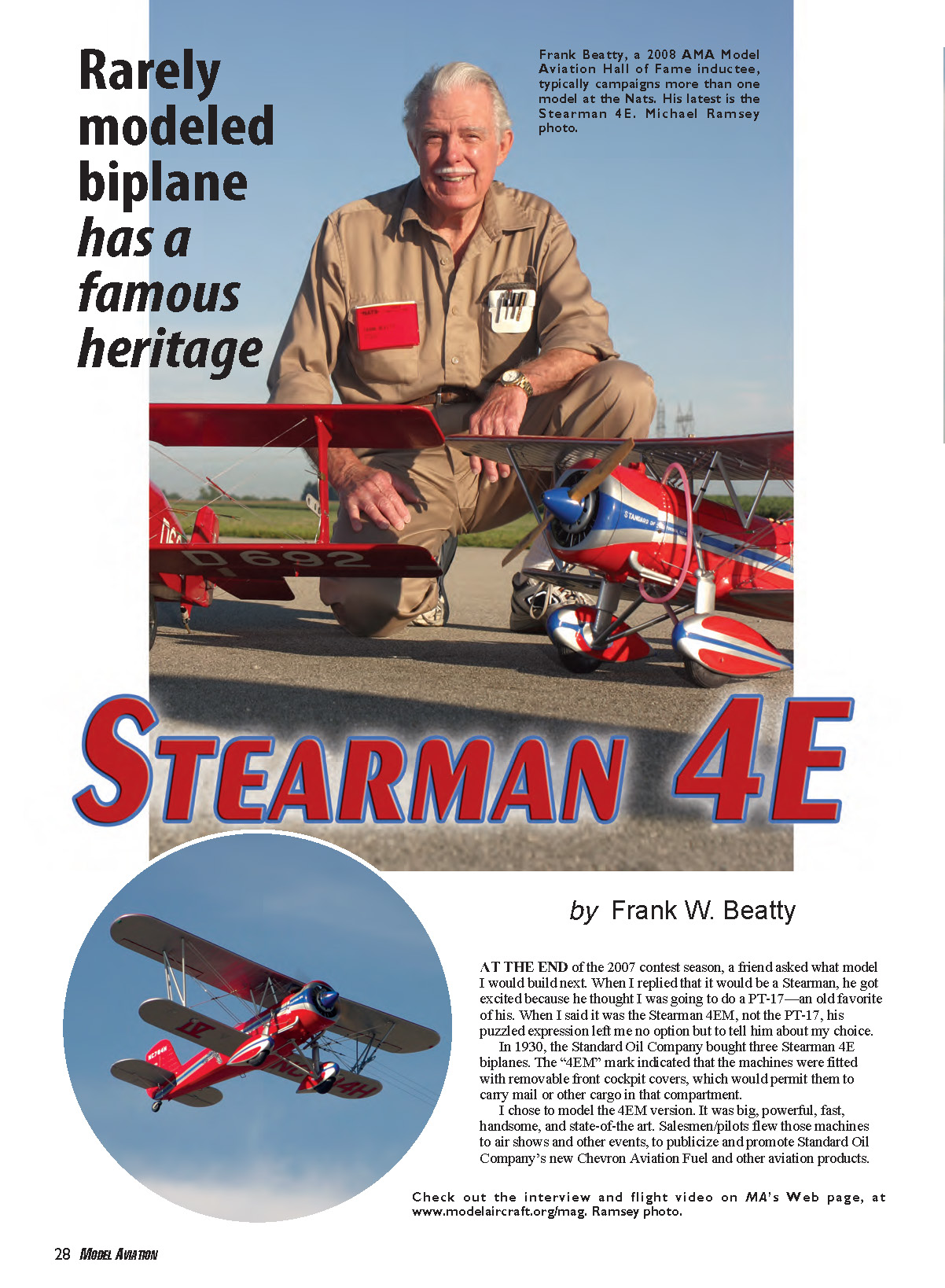
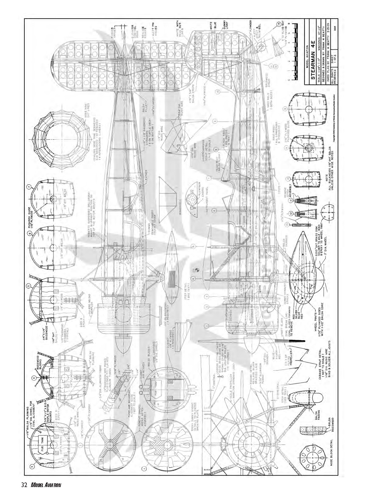
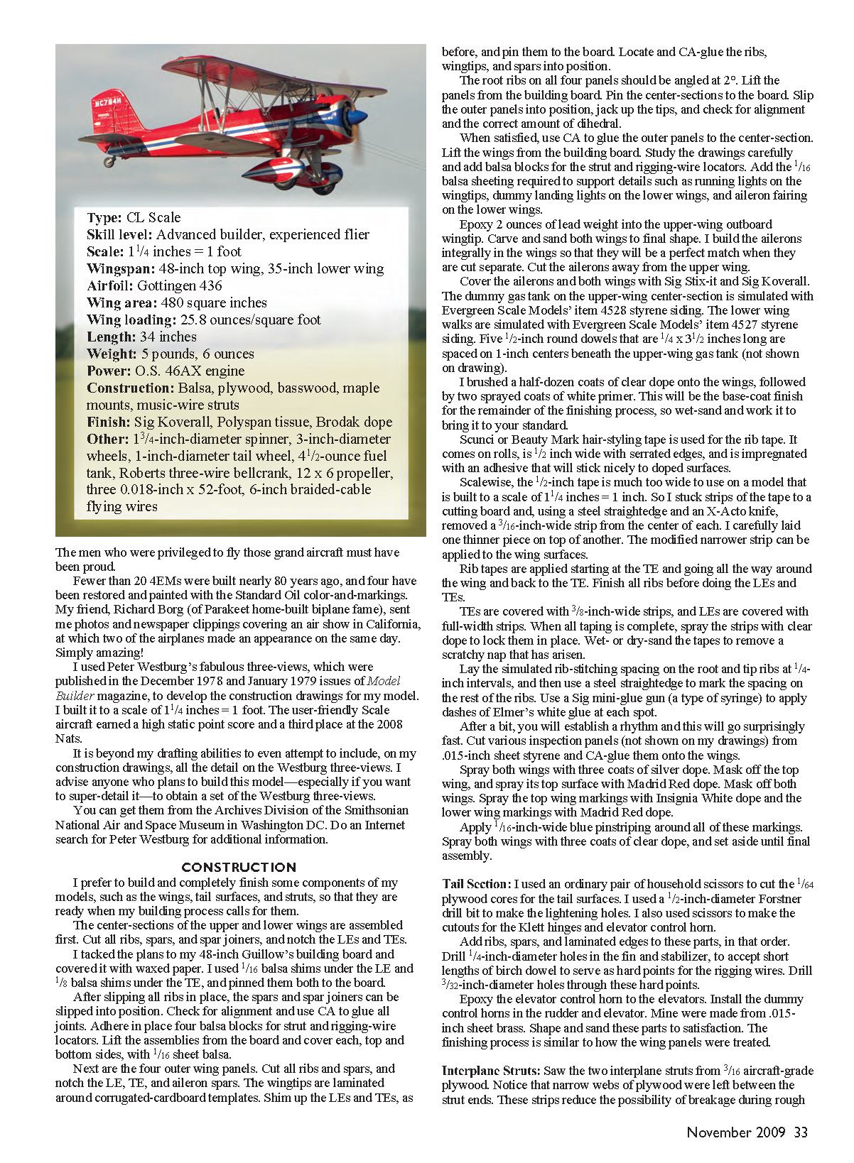
STEARMAN 4E
by Frank W. Beatty
At the end of the 2007 contest season, a friend asked what model I would build next. When I replied that it would be a Stearman, he got excited because he thought I was going to do a PT-17—an old favorite of his. When I said it was the Stearman 4EM, not the PT-17, his puzzled expression left me no option but to tell him about my choice.
In 1930, the Standard Oil Company bought three Stearman 4E biplanes. The “4EM” mark indicated that the machines were fitted with removable front cockpit covers, which would permit them to carry mail or other cargo in that compartment.
I chose to model the 4EM version. It was big, powerful, fast, handsome, and state-of-the-art. Salesmen/pilots flew those machines to air shows and other events to publicize and promote Standard Oil Company’s new Chevron Aviation Fuel and other aviation products.
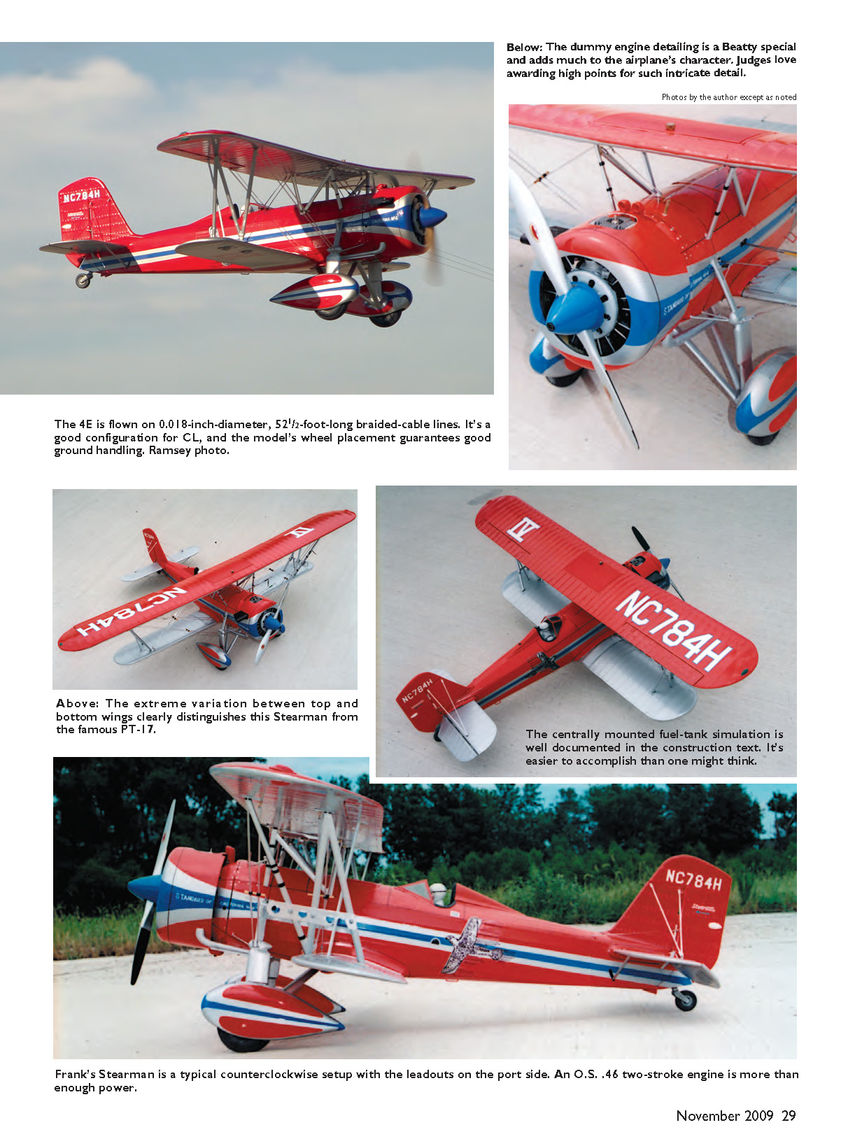
The 4E is flown on 0.018-inch-diameter, 52 1/2-foot-long braided-cable lines. It’s a good configuration for CL, and the model’s wheel placement guarantees good ground handling.
Frank’s Stearman is a typical counterclockwise setup with the leadouts on the port side. An O.S. .46 two-stroke engine is more than enough power.
The men who were privileged to fly those grand aircraft must have been proud. Fewer than 20 4EMs were built nearly 80 years ago, and four have been restored and painted with the Standard Oil color-and-markings. My friend Richard Borg (of Parakeet home-built biplane fame) sent me photos and newspaper clippings covering an air show in California at which two of the airplanes made an appearance on the same day. Simply amazing!
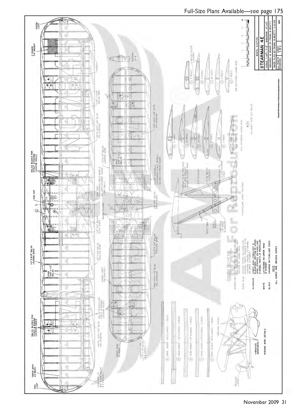
I used Peter Westburg’s three-views, published in the December 1978 and January 1979 issues of Model Builder magazine, to develop the construction drawings for my model. I built it to a scale of 1 1/4 inches = 1 foot. The user-friendly scale aircraft earned a high static point score and a third place at the 2008 Nats.
It is beyond my drafting abilities to include all the detail on the Westburg three-views in my construction drawings. I advise anyone who plans to build this model—especially if you want to super-detail it—to obtain a set of the Westburg three-views. You can get them from the Archives Division of the Smithsonian National Air and Space Museum in Washington, D.C. Do an Internet search for Peter Westburg for additional information.
CONSTRUCTION
I prefer to build and completely finish some components of my models, such as the fuselage, tail surfaces, and struts, so that they are ready when my building process calls for them.
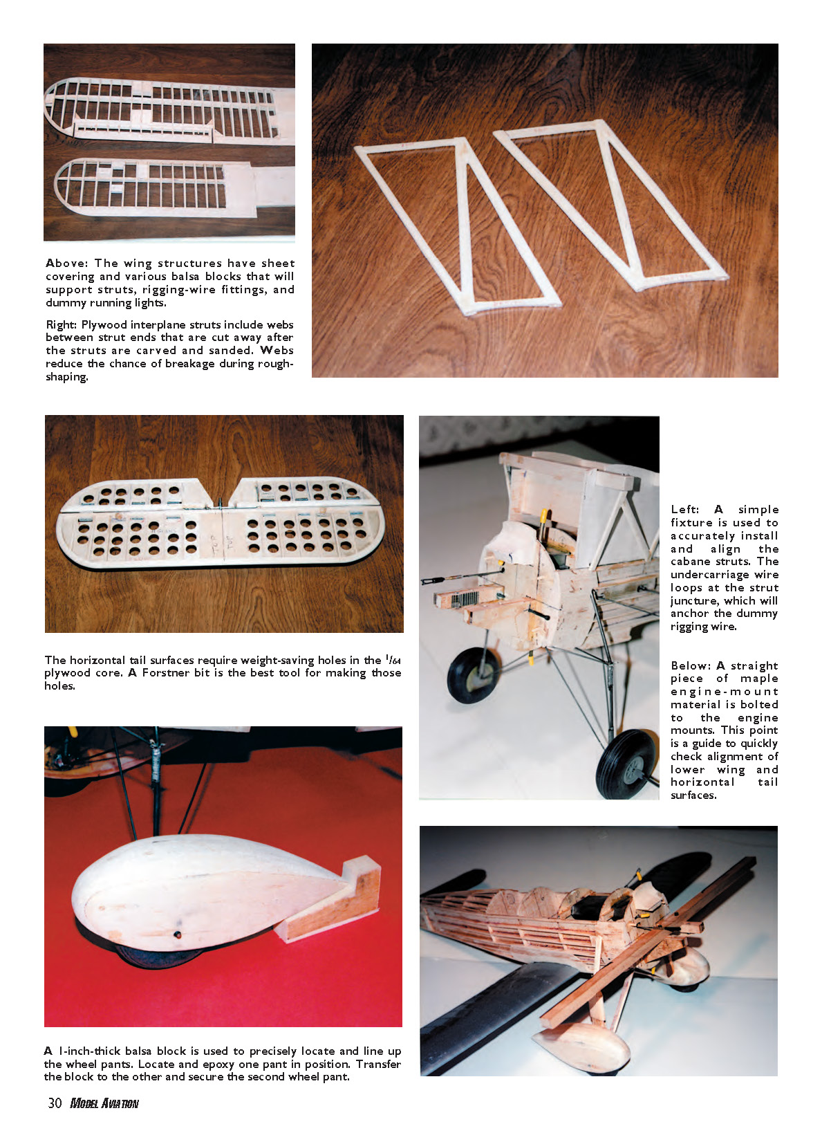
The center-sections of the upper and lower wings are assembled first. Cut all ribs, spars, and spar joiners, and notch the leading edges (LEs) and trailing edges (TEs).
Tack the plans to a 48-inch Guillow's building board and cover it with waxed paper. I used 1/16-inch balsa shims under the LE and 1/8-inch balsa shims under the TE, and pinned them both to the board. After slipping all ribs in place, the spars and spar joiners can be slipped into position. Check the alignment and use CA to glue all joints. Add filler blocks for strut and rigging-wire locators. Lift the assemblies from the board and cover each, top and bottom, with 1/16-inch sheet balsa.
Next are the four outer wing panels. Cut all ribs and spars, and notch the LE, TE, and aileron spars. The wingtips are laminated around corrugated-cardboard templates. Shim up the LEs and TEs as before and pin them to the board. Locate and CA-glue the ribs, wingtips, and spars into position.
The root ribs on all four panels should be angled at 2°. Lift the panels from the building board. Pin the center-sections to the board. Slip the outer panels into position, jack up the tips, and check for alignment and the correct amount of dihedral. When satisfied, use CA to glue the outer panels to the center-section. Lift the wings from the building board. Study the drawings carefully and add balsa blocks for the strut and rigging-wire locators. Add the 1/16-inch balsa sheeting required to support details such as running lights on the wingtips, dummy landing lights on the lower wings, and aileron fairing on the lower wings.
Epoxy 2 ounces of lead weight into the upper-wing outboard wingtip. Carve and sand both wings to final shape. I build the ailerons integrally in the wings so that they will be a perfect match when they are cut separate. Cut the ailerons away from the upper wing.
Cover the ailerons and both wings with Sig Stix-it and Sig Koverall. The dummy gas tank on the upper-wing center-section is simulated with Evergreen Scale Models item 4528 styrene siding. The lower wing walks are simulated with Evergreen Scale Models item 4527 styrene siding. Five 1/4-inch round dowels that are 3-1/2 inches long are spaced on 1-inch centers beneath the upper-wing gas tank (not shown on drawing).
I brushed a half-dozen coats of clear dope onto the wings, followed by two sprayed coats of white primer. This will be the base-coat finish for the remainder of the finishing process, so wet-sand and work it to bring it to your standard.
Scunci (or Beauty Mark) hair-styling tape is used for the rib tape. It comes on rolls, is 1/2 inch wide with serrated edges, and is impregnated with an adhesive that will stick nicely to doped surfaces. Scale-wise, the 1/2-inch tape is much too wide for a model built to a scale of 1 1/4 inches = 1 foot. So I stuck strips of the tape to a cutting board and, using a steel straightedge and an X-Acto knife, removed a 3/16-inch-wide strip from the center of each. I carefully laid one thinner piece on top of another. The modified narrower strip can be applied to the wing surfaces.
Rib tapes are applied starting at the TE and going all the way around the wing and back to the TE. Finish all ribs before doing the LEs and TEs. TEs are covered with 3/8-inch-wide strips, and LEs are covered with full-width strips. When all taping is complete, spray the strips with clear dope to lock them in place. Wet- or dry-sand the tapes to remove a scratchy nap that may arise.
Lay the simulated rib-stitching spacing on the root and tip ribs at 1/4-inch intervals, and then use a steel straightedge to mark the spacing on the rest of the ribs. Use a Sig mini-glue gun (a type of syringe) to apply dashes of Elmer's white glue at each spot. After a bit, you will establish a rhythm and this will go surprisingly fast. Cut various inspection panels (not shown on my drawings) from .015-inch sheet styrene and CA-glue them onto the wings.
Spray both wings with three coats of silver dope. Mask off the top wing and spray its top surface with Madrid Red dope. Mask off both wings. Spray the top wing markings with Insignia White dope and the lower wing markings with Madrid Red dope. Apply 1/16-inch-wide blue pinstriping around all of these markings. Spray both wings with three coats of clear dope, and set aside until final assembly.
Tail Section
I used an ordinary pair of household scissors to cut the 1/64-inch plywood cores for the tail surfaces. I used a 1/2-inch-diameter Forstner drill bit to make the lightening holes. I also used scissors to cut the 1/16-inch balsa sheeting to go over the cores. The Klett hinges and elevator control horns are installed in the usual manner.
Add ribs, spars, and laminated caps to these parts, in that order. Drill 1/16-inch-diameter dowel holes in the fin and stabilizer to accept short lengths of 1/16-inch dowel to serve as hard points for the rigging wires. Drill 1/32-inch-diameter holes through these hard points.
Epoxy the elevator control horn into the elevators. Install the dummy control horns in the rudder and elevator; mine were made from .015-inch sheet brass. Shape and sand these parts to satisfaction. The finishing process is similar to how the wing panels were treated.
Interplane Struts
Saw the two interplane struts from 3/16-inch aircraft-grade plywood. Notice that narrow webs of plywood were left between the strut ends. These strips reduce the possibility of breakage during rough shaping. Bevel, carve, and sand the struts to a faired airfoil. Drill holes for the rigging wires as shown on the drawings and finish as desired.
Drill 1/16-inch-diameter holes 3/4 inch deep into the end of each strut. These will accept lengths of 4-40 threaded rod, which will be epoxied into the strut ends. During final assembly, these threaded ends will be epoxied into the various strut locators. I have never had such a joint fail. Dope, prime, and paint the struts silver.
Bolt a 1/16-inch sheet-aluminum line guide to the port strut. The unusual cutout in the guide is necessary to accommodate a scale aileron-control strut. Bind a wire dummy pitot tube to the port strut with 1/16-inch-wide strips of black electrician’s tape. Set these struts aside for now.
Fuselage
I used a piece of 3/4-inch-diameter Reynolds aluminum tubing to make the fuselage crutch alignment fixture (shown in the isometric sketch on Sheet No. 1). I prefer to laminate two pieces of 1/16-inch sheet balsa with the grain running at right angles for those bulkheads that are notched for stringers. This reduces breakouts when installing the stringers.
Examine the fuselage side view carefully to lay all the 1/8 x 7/16-inch slots on the fuselage crutch members. These slots accept tabs on each bulkhead during assembly. I cut the tabs on the bulkheads extra-long (about 1/4 inch) so that the bulkheads will stay engaged during the assembly process. I also draw centerlines on both sides of all parts; they invariably come in handy later.
Use CA to adhere 1/32 x 6-inch-long plywood doublers on the fuselage sides (recommended, although not shown on my drawings). The bulkheads and fuselage sides are assembled on the 3/4-inch-diameter aluminum tube. This simple fixture prevents the dreaded banana-fuselage misalignment syndrome. CA-glue all joints, and trim the protruding tabs flush with the fuselage sides.
Install the balsa fairing block at the nose, and install the basswood longerons and stringers on the fuselage sides. With that, the structure will be stable enough to remove the aluminum tubing.
Bend up and bind the main 1/8-inch-diameter music-wire undercarriage strut to Bulkhead No. 4. Bend up and bind the two 1/16-inch-diameter music-wire struts to Bulkhead No. 3 and No. 4 and onto the main strut. These auxiliary struts will determine the main struts’ alignment, so fitting these parts accurately is important. Bend up and bind the four 5/64-inch-diameter music-wire struts to Bulkhead No. 4 and No. 5.
Notice the short right-angle lengths on these struts that are pushed through locator holes in the bulkheads. They serve two purposes: first, to provide a set location for one end of the strut during the forming and fitting process; second, to reduce the possibility that the struts will be dislodged on a hard landing.
Install the maple engine mounts and 1/8-inch plywood gussets. Cut a three-wire bellcrank to fit between Bulkhead No. 4 and No. 5. Install leadouts on the bellcrank. Bolt it and the engine in place on the engine mounts.
Temporarily pin the horizontal tail surfaces on the fuselage. Cement the two plywood elevator-pushrod guides to Bulkhead No. 7 and No. 9. Make and install the throttle and elevator pushrod linkages. CA-glue the 1/4-inch square basswood cabane-strut locators to Bulkhead No. 4 and No. 5.
Construct a simple fixture and tack-glue it to the fuselage. This allows an accurate set of cabane struts to be built in situ on the fuselage. While still in the fixture, apply the balsa fairings to the struts. If the balsa fairings’ top ends are trimmed correctly, they will automatically align the upper wing during final assembly. Remove the struts until final assembly. This makes planking and finishing procedures on the fuselage much easier.
Epoxy the 4-1/2-ounce fuel tank into the fuselage. Install the 1/8-inch sheet-balsa pilot support and a balsa block on the rear side of Bulkhead No. 4. That block will support rigging-wire fittings later. Plank the fuselage top, and install the basswood stringers on the turtledeck.
The tail cone takes all of the tail-wheel landing shocks, so it is made from plywood and basswood parts. I used a Klett tail-wheel fork assembly, which I anchored into a blind mounting nut with J.B. Weld. Those Klett tail-wheel assembly kits are no longer manufactured. If you cannot find one, you must develop an alternate setup. Set the tail-cone assembly aside.
Undercarriage
The wheel pants are made from balsa cores and 1/32-inch plywood sides. I build them in halves, split down the middle, with two 1/8-inch-diameter dowel pins to maintain alignment between the halves. This simplifies the hollowing-out process.
Make two .010-inch-sheet brass disks and solder them to the undercarriage axles. Slip an inboard pant half and a wheel onto an axle. Prop up the fuselage and, using the 1-inch balsa guide block, align and mark the wheel-pant locations on the disks. Bind and epoxy the pant half to the disk. Solder the wheel to the axle, and cement the outer pant half to the assembly. Mount the second pant in the same fashion. Using that alignment block has turned a tedious task of accurately aligning two wheel pants into a no-brainer.
Solder the rigging-wire fittings to the main strut, and then all balsa strut fairings can be installed on the undercarriage.
Cowling
The cowling framework is built with Bulkhead No. 1 and No. 2, four basswood spacers, and a 1/32-inch plywood wraparound. The plywood webs on Bulkhead No. 2 can be cut away after the cowling has been assembled, using a short piece of 3/4-inch aluminum tubing to align the parts.
The cowling nose ring consists of 32 3/16-inch basswood segments in four interlocking tiers. I adhered these with Elmer’s carpenter’s glue and then cut them to an outline on my scroll saw. I tack-glued that ring to a round 1/4-inch plywood plate with a centering bolt. When that bolt was chucked in my drill press, I brought the ring to shape using rasps, files, and sandpaper.
I constructed an intermediate cowling block with a series of balsa blocks. The main cowling and intermediate block will not be cemented together until after the finishing processes on these parts are completed. These two assemblies will be removed and replaced countless times during the building and finishing process, so each has four 1/8-inch-diameter birch-dowel alignment pins that will maintain consistent placement between all parts during construction and finishing. A 2-inch-wide portion of the intermediate cowling is cut away and epoxied to the firewall, which is Bulkhead No. 3.
Bolt the engine in place. Lay out and make cutouts for the cylinder head, muffler, and needle-valve access. My O.S. engine featured a rear needle valve on a bracket, which I removed and relocated with the needle valve in an upright position.
Assembly
I bolted an 18-inch length of maple engine-mount material to the engine mounts. Then I pinned the lower wing and stabilizer into position. Sighting down this primitive system allows these parts' alignment to be "eyeballed" fairly closely. Then more sophisticated methods (levels, rulers, and height gauges) can be used to achieve dead-on accuracy.
The bottom of the fuselage can be finished with planking and stringers. Install the elevators and hook up the elevator pushrod. Now the tail cone can be epoxied to the fuselage. Install the fin and its fairing.
There is concern about the model's becoming excessively tail-heavy, so I cut away a great deal of 1/16-inch sheet-balsa crutch aft of Bulkhead No. 6 before covering the fuselage. The 4E has a 3 1/2-to-1 moment arm, so an ounce removed from the rear will save adding 3 or 4 ounces of ballast to the model's nose.
I filled all dings with Red Devil lightweight spackling compound and sanded the fuselage to my satisfaction. I cover straightforward components such as wings and tail surfaces with Sig Koverall. But I find it easier to cover shapes such as fuselages, where material will overlap, with Polyspan tissue.
The fillets between the wing and fuselage are carefully carved and fitted balsa blocks. The fillets at the tail are made from the Red Devil spackling compound.
Painting
My friend Tim Pansic, who is retired from an oil refinery, has amassed a large collection of old oil cans. We compared the colors on an old Standard Oil can with the colors on a Brodak-dope color chart. The Brodak Madrid Red and Miami Blue were almost matches. All dopes, primers, and thinners used on the Stearman were Brodak products.
Protect the previously finished wings and horizontal tail surfaces with paper sleeves and masking tape. The fuselage is worked up through the customary clear dope and primer dope process. The Beauty Mark tapes are narrowed to 3/16-inch widths by the previously discussed process and then are applied on all the longerons and stringers on the fuselage.
A couple coats of clear dope are followed by several coats of silver. When the silver is being masked off, mask off an area on the fuselage sides to accommodate the eagle on the fuselage. Spray on the Madrid Red. Additional masking will permit the Miami Blue striping to be brushed on.
To make the "Standard of California" and eagle markings, I coated a 12-inch square of glass with a film of soapy water, taking care to eliminate as many bubbles as possible. When dry, I sprayed the pane with several coats of clear dope. When that was dry, I laid the plate over a copy of the images I wanted to duplicate. I drew the eagle with a black Top Flite panel-line pen. The "Standard of California" was lettered with white FW Acrylic Artist Ink and a pen. I protected those images with an overspray of clear dope.
I traced around the graphics with a No. 11 X-Acto knife. The soapy water I applied to the glass acts as a release agent, and the images can be peeled off. Elmer's yellow carpenter's glue is diluted to a thin consistency and painted over the area where the markings will be applied. Then three coats of clear dope are sprayed over the fuselage. (Markings for the rudder could have been made in the same fashion.)
Cut out the cockpit and paint the inside silver. Install the instrument panel, leather cockpit coaming, and windshield. Mask off the windshield and brush red dope for the frames.
Details
Rigging-wire fittings are made from twistings of 20-gauge brass wire. Buttering epoxy onto those wire ends will anchor them into locator holes with an unbreakable grip.
Epoxy the cabane-strut ends into the fuselage. Temporarily assemble the interplane struts and top wing onto the airframe. If you have done accurate work on these struts, alignment should be close. Tweak it to your satisfaction. Coat all strut ends with epoxy and reassemble the structures.
The rigging is simulated with Rexlace Brite Silver lacing material, which you can obtain at craft shops. Slip two 3/32-inch-diameter by 1/2-inch-long aluminum tubing sleeves onto a length of lacing material. Loop one end through a fitting and draw that end through the tubing sleeve, crimp the tubing, and touch it with a drop of CA. Stretch the lace taut and repeat the process on the other end. Repeat this procedure for all of the remaining wires. The Rexlace material is strong, flexible, and fuelproof. Its flexibility allows it to take shocks and strains without breaking and remain taut.
The front halves of an old Monogram kit’s (item PE52-198) Wright Cyclone engine cylinders are epoxied to the webs on Bulkhead No. 1. You can dress up these cylinders with aluminum-tubing pushrods and ignition-harness wiring.
The step on the wheel pants is simulated with a grid of 1/32-inch-wide striping tape that is brushed with silver dope. Additional details such as exhaust stacks, steps, handholds, fuel caps, landing lights, and running lights can be installed now.
I carved the scale propeller from a piece of basswood. Brodak’s B-25 Silver will give the propeller a finish that looks almost like real metal. I obtained the Hamilton Standard Company logo decals from Northeast Screen Graphics.
A model looks naked without a pilot, and AMA contest rules require that our models be fitted with one. Techniques from Don Typond’s videotape, How to Paint Pilot Figures, brought a Williams Brothers 1/12-scale pilot to life before I "seated" it in the cockpit.
I assembled the entire airplane with all components installed and checked for balance. I needed to add 5 or 6 ounces of ballast in the bottom of the cowling to achieve proper balance. At this point I could epoxy the intermediate cowling block to the main cowling assembly.
We are ready to head out to the flying field.
Flying
I checked the Stearman for balance and epoxied roughly 6 ounces of lead into the bottom of the cowling to bring the model to proper balance for CL. Depending on your building and finishing techniques, your model might require more or less ballast than mine did.
The 4E is flown on 0.018-inch-diameter by 52 1/2-foot braided-cable lines. It has a good configuration for CL flying, and its wheel placement guarantees good ground handling.
The airplane has ample power and a fairly light wing loading, so it flies with spirit. It can handle the 45° high-flight contest option with ease.
I point out to the Scale flight judges that the full-scale airplane was fast (158 mph) so that they won’t deduct points for an inappropriately high scale speed.
I have a thoroughbred in my stable of Scale models. On the contest trail, you can go far with this classy, classic biplane! Adieu!
Frank W. Beatty [email protected]
Sources
- Smithsonian National Air and Space Museum — www.nasm.si.edu
- Sig Manufacturing — (800) 247-5008, www.sigmfg.com
- Evergreen Scale Models — (877) 376-9099, www.evergreenscalemodels.com
- Brodak Manufacturing — (724) 966-2726, www.brodak.com
Transcribed from original scans by AI. Minor OCR errors may remain.

