
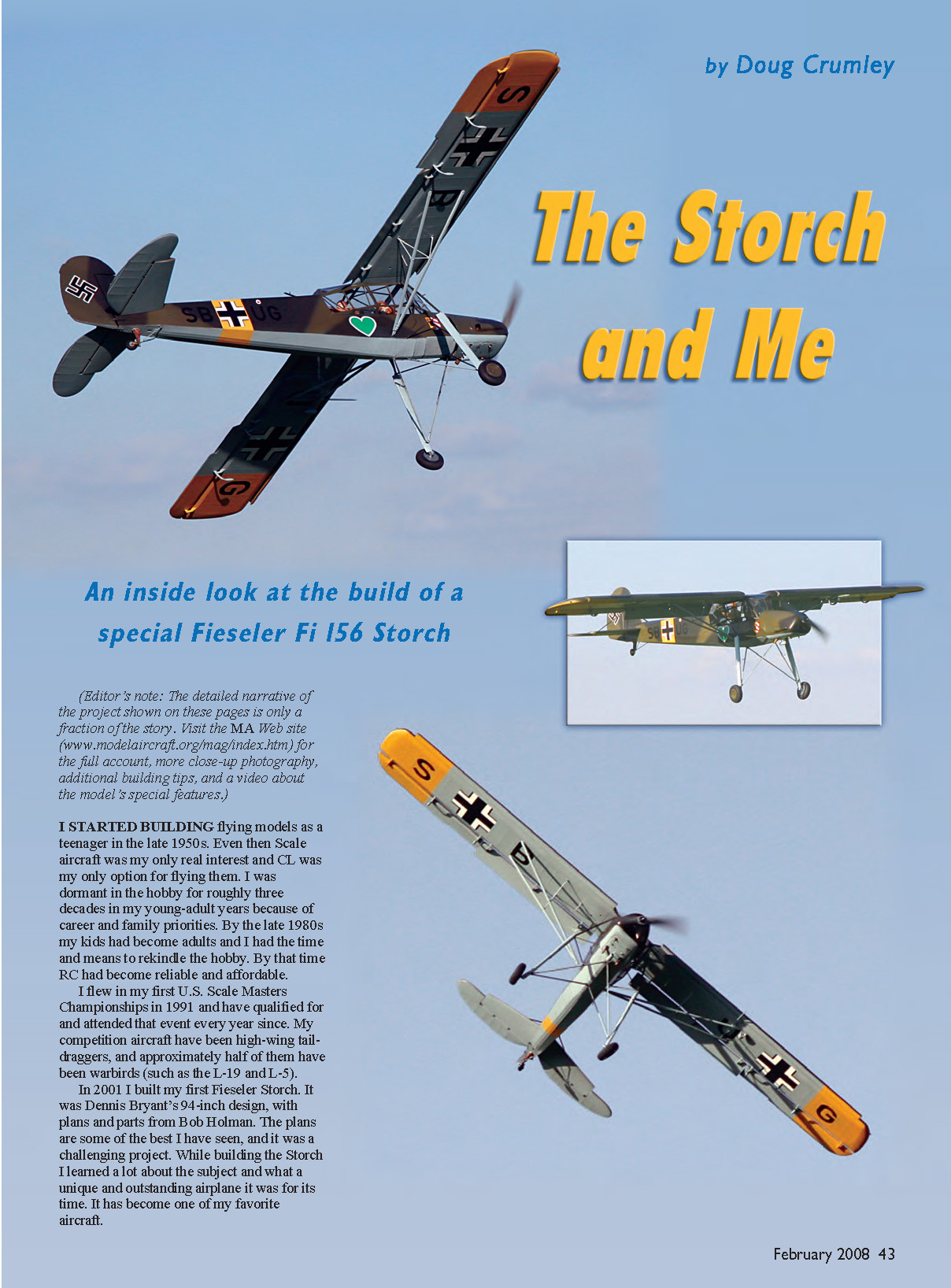
The Storch and Me
by Doug Crumley
(Editor’s note: The detailed narrative of the project shown on these pages is only a fraction of the story. Visit the MA web site (www.modelaircraft.org/mag/index.htm) for the full account, more close-up photography, additional building tips, and a video about the model’s special features.)
I started building flying models as a teenager in the late 1950s. Even then, scale aircraft was my only real interest and CL was my only option for flying them. I was dormant in the hobby for roughly three decades in my young-adult years because of career and family priorities. By the late 1980s my kids had become adults and I had the time and means to rekindle the hobby. By that time RC had become reliable and affordable.
I flew in my first U.S. Scale Masters Championships in 1991 and have qualified for and attended that event every year since. My competition aircraft have been high-wing taildraggers, and approximately half of them have been warbirds (such as the L-19 and L-5).
In 2001 I built my first Fieseler Storch. It was Dennis Bryant’s 94-inch design, with plans and parts from Bob Holman. The plans are some of the best I have seen, and it was a challenging project. While building the Storch I learned a lot about the subject and what a unique and outstanding airplane it was for its time. It has become one of my favorite aircraft.
(No primary-article body text appears on this scanned page — it contains only photographs and photo captions.)
What's to like about the Storch? Its sleek, flowing, aerodynamic lines? Hardly. The aircraft looks as if it were designed by a committee of architects and structural engineers that had never heard the term "parasite drag."
However, the Storch has a distinctive look and always gets attention at the flying field. Its "unclean" appearance lends itself to an incredible amount of small surface-detail work, if you are so inclined.
In spite of its looks, the Storch was probably the best aircraft ever designed to accomplish its intended function, which was to take off and land in the smallest space and on the roughest surface possible. Even today, if you want an aircraft that will get in and out of tighter spaces than the Storch, you use a helicopter.
My first Storch went to the Scale Masters for two successive years. I really liked it, but it had some shortcomings that left me wanting to do better. First, even spanning 94 inches the model was only 1/6 scale; that was small for competition. All my other aircraft have been 1/4 scale, which is much easier to detail.
The second problem applies to almost all model designs of high-wing aircraft. Typical model-construction methods leave fuselage bulkheads extending into the cockpit area, making an accurate cockpit interior nearly impossible. This is further complicated when the designer extends the wing-spar structure across the top of the cockpit.
When a subject, such as the Storch, has a full greenhouse cockpit, the cockpit interior is an important part of the presentation. And there is only so much you can do to approximate a scale appearance using conventional model construction methods and materials.
Ed Newman is a friend and fellow Scale competitor who has been modeling the Storch for many years. He has developed his own design, produced plans, and commissioned fabrication of critical structural components, which allows a modeler to build an exceptional subject.
Knowing about my interest in the Storch, Ed asked if I would like to build one of his designs and share my evaluation of his efforts with you fellow modelers. I accepted the offer, but this will not be your typical kit-review article.
For one thing, I have never built an airplane per the plans. I can't even put an ARF together without making a few modifications. Also, roughly 75% of this airplane is of typical model construction. I don't see any point in telling you how to frame a wing. I just want to show you the 25% that makes this worthy of a story.
In addition, since this is the second Storch I have built, I applied lessons learned from the first one to it. If you like what you see here, check out the Internet presentation of this story.
CONSTRUCTION
Ed's design is 1/5 scale with a 112-inch wing. The plans are excellent-quality full-size CAD drawings. He has produced CAD drawings for Proctor kits for some time.
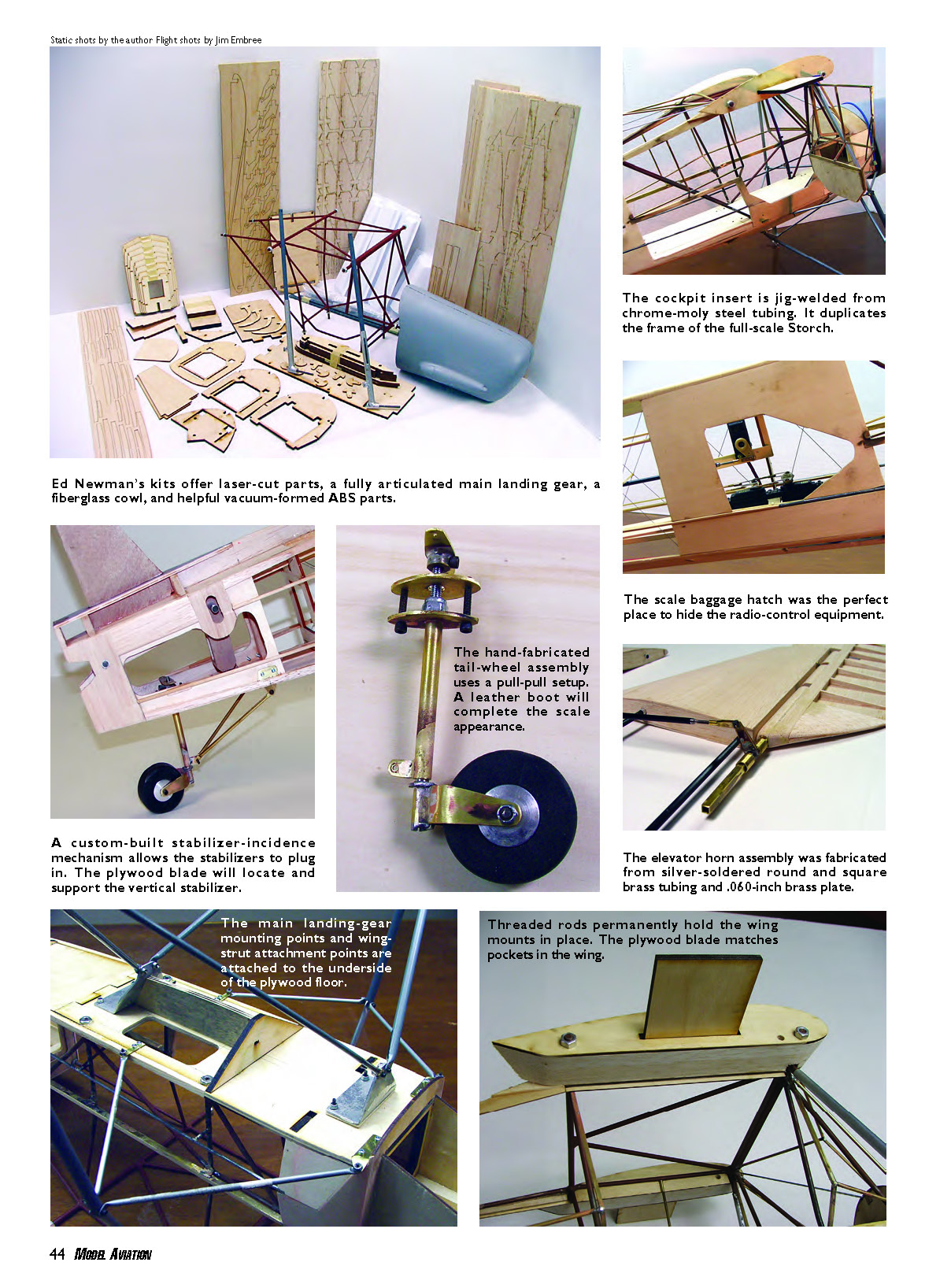
Ed offers laser-cut ribs, formers, and plywood parts. A fully articulated main-landing-gear assembly is a must-have unless you have a machine shop. There is an excellent fiberglass cowl and helpful vacuum-formed ABS parts.
The key component that sets these plans apart from all others is the cockpit insert. This is jig-welded from aircraft-quality chrome-moly steel tubing. It duplicates the full-scale Storch’s tube frame within the cockpit area. It is fully structural and supports the wings, struts, and main landing gear.
The Storch’s front and side windows are faceted, planar surfaces, so the frames are intersecting straight lines. I chose to work with brass tubing, round and square, and soldered all the pieces in place.
Along the top edge of the cabin wall, where it meets the lower down-looking side windows, I used 1/4-inch-angle brass to form the structural edge. Then I glued 1/4-inch-square basswood into the angle. This was necessary to give a wood surface to which the outer fabric would attach.
As I worked my way through this project I called on every skill I have developed during years of Scale building, used the entire contents of my toolbox, and may have added a few more skills and tools in the process. I’ll share some areas of this project you might find useful in yours.
For any good solder joint the parts should be fit as tight as possible and all surfaces should be sanded clean. Do not let the torch melt the solder. The material needs to be hot enough to melt the solder when touched to it.
Be careful with Mapp gas on brass or copper. As these metals reach the silver-solder melt temperature, they become cherry red. Be quick with the silver at that point because the Mapp gas can easily melt the part.
Ed’s tail-section design is basic model construction that is similar to that of many other aircraft of this type. There’s nothing wrong with that, but having built the Storch before there were lessons learned that I wanted to address and incorporate into this project. I also wanted a higher degree of scale detail than his design allowed.
This aircraft has large tail feathers. The horizontal span is approximately 37 inches. I wanted a plug-in horizontal stabilizer for transport flexibility. It also improves scale accuracy since the full-scale aircraft had a variable-incidence trim, similar to a Piper Cub.
In addition, the plug-in stabilizer allows the fuselage and tail surfaces to be covered and painted separately, as was done with the full-scale Storch. It also allowed me to build in a mechanism to ground-adjust the horizontal stabilizer’s incidence.
The Storch has an exceptionally long, slender fuselage with a nearly rectangular cross-section. It will twist effortlessly unless it’s extensively crossbraced. Ed’s plans show many traditional 1/4-square crossbraces. Many World War I aircraft were similar; internal cables and turnbuckles were often used as crossbracing. I wondered if I could simplify that idea.
With the cables and longerons held in place only by friction, they would maintain a set position but could be twisted into a new arrangement. Once I achieved a set position with the front square with the rear, I applied thin cyanoacrylate to all the joints and cable holes. That permanently locked the position.
Once all the joints and holes were glued securely, I added tension to the cables by drawing the Xs together with Kevlar string. This worked well. It was quick, lightweight, and an easy way to square up the tail.
While documenting the subject of a project approximately 15 years ago, I learned that it had been finished with Stits Poly-Tone paints. To get a match I went to the local aircraft supplier and got the same paints he had used. My color documentation for that project was perfect.
Shortly thereafter, Chip Mull came to our club meeting to demonstrate the product line for a business he was starting: F&M Enterprises. The material was Stits Lite fabric for modelers. Chip was just in time for my next project, and the subject had also been covered and painted with the Stits system. Once again my color documentation was dead-on, and I have used Chip’s products on every model since then.
Covering — the Stits system’s advantages would require a complete article, and many have been written about it. One of the benefits for a project such as this is that Chip sells Stits Lite by the yard, and he cuts it from a 60-inch-wide roll to any length requested. I ordered 4 yards for the Storch.
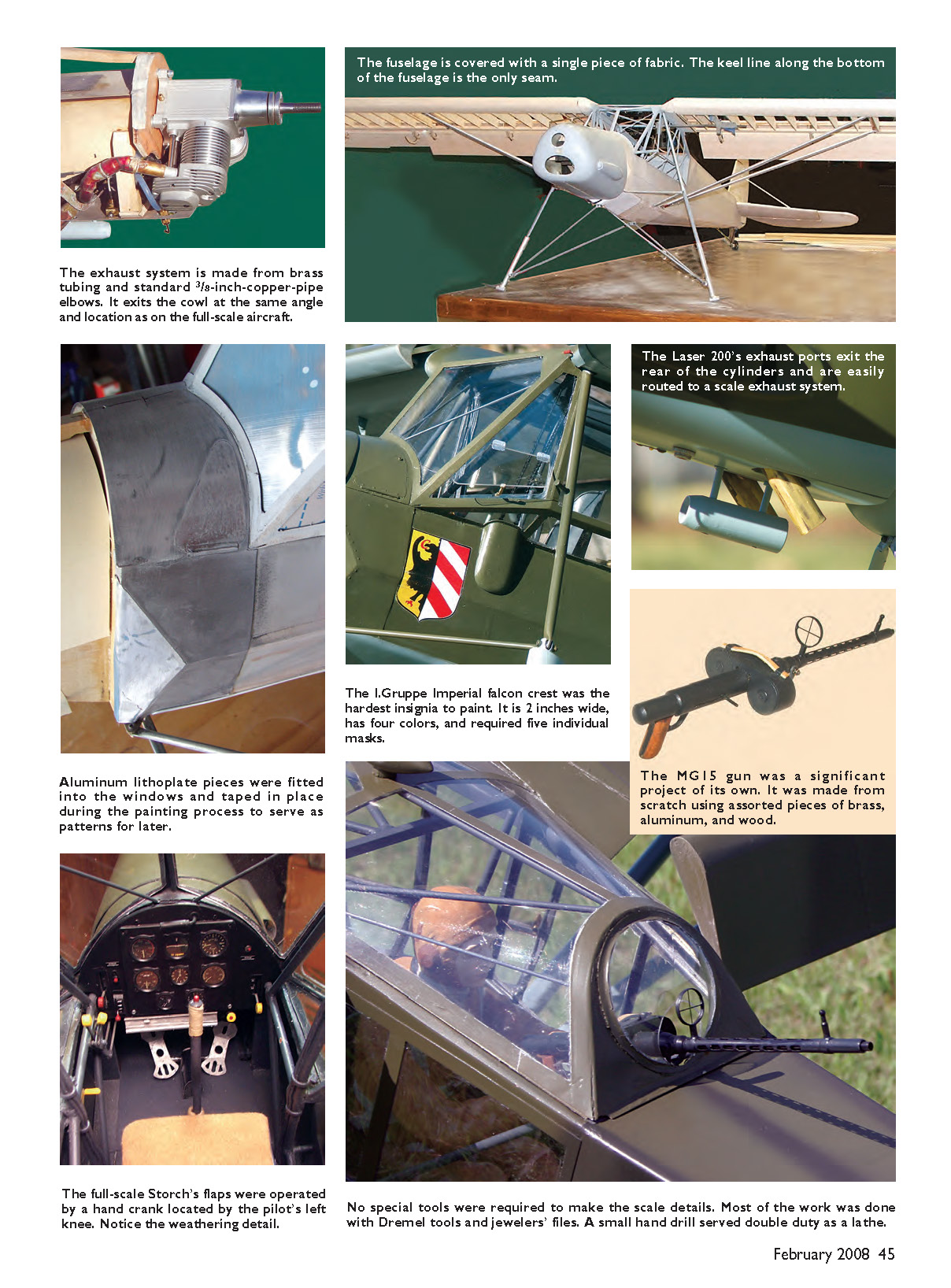
Because of this, and because I had built the tail surfaces to plug in separately, I was able to cover the fuselage with a single piece of fabric. The keel line along the bottom of the fuselage is the only seam.
Finish
An excellent documentation source is the plastic modeling industry. Most of those manufacturers thoroughly research their subjects for accuracy and offer a selection of finishing options that are well documented for color and markings.
A 1/32-scale Hasegawa kit supplied all the information I needed for an interesting subject. The German RLM (Reich Aviation Ministry) colors and decal placement are clearly defined in all views. I scanned the decal sheet and scaled it up to the correct size to use as patterns. The decal sheet is part of my documentation package for judging.
The Stits paints dry to a semigloss finish. Gloss is achieved by using clear Stits with a retarding thinner. You can add a flattening agent to the last color coat for a matte finish. The same effect can be obtained with a spray technique.
When I am satisfied with the coverage of the main colors, I apply a coat with an airbrush. I hold the airbrush farther than usual from the surface so the paint begins to dry as it contacts the surface. I keep the airbrush moving so the droplets cannot break surface tension with each other and gloss over.
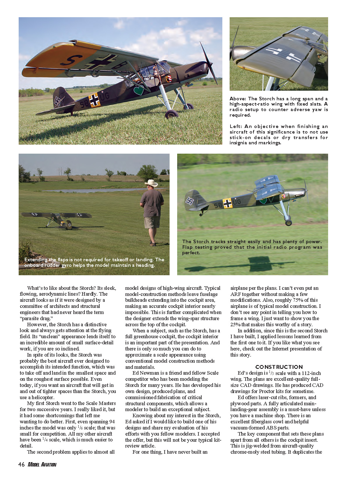
One of my objectives in finishing an aircraft of this significance is to not use stick-ons, decals, or dry transfers for insignia and markings. I masked and painted all of them. I scanned the Hasegawa decal sheet into Photoshop, enlarged the images from 1/32 to 1/5 scale, cleaned up any imperfections, and created individual JPEG files.
Walt Farrell, a friend and fellow modeler, frequently judges at the Kansas City Regional Qualifier I attend each summer. He has his own computer laser and offered to cut all my masks from frisket paper. What a great friend to have!
Power and Systems
Making the Storch perform well requires special considerations when setting up the flight controls. It does not fly like a Cub. Incorporating all the full-scale aircraft’s control features requires a high-end computer radio. I am using an Airtronics Stylus PCM transmitter with the Aero Card.
The Storch has a long-span, high-aspect-ratio wing with full-span fixed slats. This makes adverse yaw a significant factor, and the aircraft will tend to oscillate in yaw while in level flight through smooth air. I installed a gyro on the rudder to compensate for this attribute. My setup has the gyro on anytime the receiver is on.
Modern gyros are electronic with no mechanical parts and use little battery power. However, the rudder servo will operate continuously, so a strong, double-ball-bearing servo should be used. An open channel is used to switch between high and low gain settings. The low setting is adjusted to zero, or off.
A gyro does not prevent the aircraft from turning. Oriented on the vertical axis and coupled to the rudder servo, it can only detect and respond to yaw. There is no yaw in a properly coordinated turn. You can still override the gyro and turn the aircraft with rudder input.
For instance, a stall turn would be performed the same, with or without the gyro; however, it reduces oscillation on the up- and down-lines. The gyro will fine-tune rudder input in turns, smooth the in-flight oscillations, and respond to crosswind gusts on takeoff and landing before you can see it occurring.
Separating the channels for both aileron servos is essential. This allows for an aileron-differential setup, which will decrease adverse yaw. That occurs because the down aileron increases the undercamber of the wing, increasing lift to roll the aircraft, but it also increases drag, which yaws the aircraft in opposition to the desired direction of the turn.
The up aileron acts as a spoiler to reduce lift on the opposite wing and does not induce the same drag. Rudder input is required to compensate and coordinate the turn. Aileron differential reduces this effect. I use roughly twice the up aileron travel as down. I also use aileron/rudder mix.
The Stylus uses a three-position switch to select from off, low, and high settings. On my previous Storch it used an 80% aileron/rudder mix, which proved to work well at slow speed.
The full-scale Fieseler Storch was powered by an air-cooled Argus V8 engine, mounted inverted, which produced 240 horsepower. Ed Newman initially flew his 22-pound design prototype with a Saito 1.50, which delivered scalelike performance. The problem with any large single-cylinder engine is that the cylinder head sticks out of the cowl.
The engine of choice is the Laser 200V four-stroke twin, which AGC Sales Ltd. manufactures in England. It is powerful, dependable, and smooth running. I have seen many Laser twins at the Scale Masters through the years, and they have always performed flawlessly. They are manufactured in 160, 200, 240, 300, and 360 sizes.
For electrical power I am using two Li-Ion battery packs. Each is rated at 7.4 volts with a 2600 mAh capacity. These packs combined are still smaller than a single C-size Ni-Cd pack. Each is connected to a heavy-duty slide switch with a built-in charge receptacle, then to a 5.4-volt regulator, then to the receiver.
The batteries are mounted under the cowl, on top of the fuel-tank compartment. I mounted the two switch plates on the cockpit floor, just behind the pilot’s seat. They are inconspicuous and easy to access through the cabin door.
This gives me total redundancy in electrical power. With any single failure of a battery, switch, or regulator, the other set will carry the load. A full charge will be good for a full weekend of flying without recharging.
Flying
When the day for test-flying finally arrived, the Laser engine fired up beautifully and sounded great. The other pilots stood on the sidelines to watch the event and stay out of the way. It was time to launch.
The takeoff was straight and true, down the center of the runway, accompanied by the spectators’ cheers. I flew a few conservative circuits around the pattern to get the feel of the Storch and adjust the trims, and then I brought the model around for a nice, easy landing. There were more cheers from the gallery. The first flight was remarkable in that it was totally uneventful.
After a postflight inspection and a few adjustments, it was back in the air for the second flight. The objective for this attempt was to test the flaps’ operation and performance. I set up for a fly-past at approximately 100 feet altitude, reduced power to half throttle, and then selected full down on the flap switch.
Because my initial mix settings were only an educated guess, I expected a process of trial and error, making adjustments during the course of several flights to get it right.
However, I watched in amazement as the Storch continued to track level, started to slow, and, finally, required extra power to maintain altitude—just like it should have. The reverse process was equally smooth. I had gotten it right on the first shot, and after a few dozen flights I still have not changed those settings.
The Storch was very stable in slow flight with full flaps and droop ailerons. As a power-on stall condition is approached, the nose attitude is high and the aircraft starts to sink straight ahead. Adding power and slightly relaxing elevator pressure regains control. I think the gyro on the rudder contributes greatly to this low-speed controllability.
Every once in a while you get one of those perfect flying days that make this hobby special: perfect weather with the wind down the runway, a great flying site with people you enjoy being around, and going home at the end of the day with nothing to fix except an empty fuel bottle. When that includes the successful maiden flight of an aircraft you have invested more than a year in building, it just doesn't get any better.
MA
Doug Crumley [email protected]
Ed Newman's 1/5-scale Storch Kit Specifications
- Wingspan: 112 inches
- Wing area: More than 1,500 square inches
- Length: 78 inches
- Height: 17.75 inches
- Stabilizer span: 37 inches
- Weight: 22 pounds
- Power: Laser 200 or equivalent
Sources
- Ed Newman Storch kit
- F&M Enterprises
(817) 279-8045 www.stits.com
- Laser Engines
+44 (0) 1525 210596 www.laserengines.com
- MA
www.modelaircraft.org/mag/index.htm (765) 287-1256
Transcribed from original scans by AI. Minor OCR errors may remain.

