

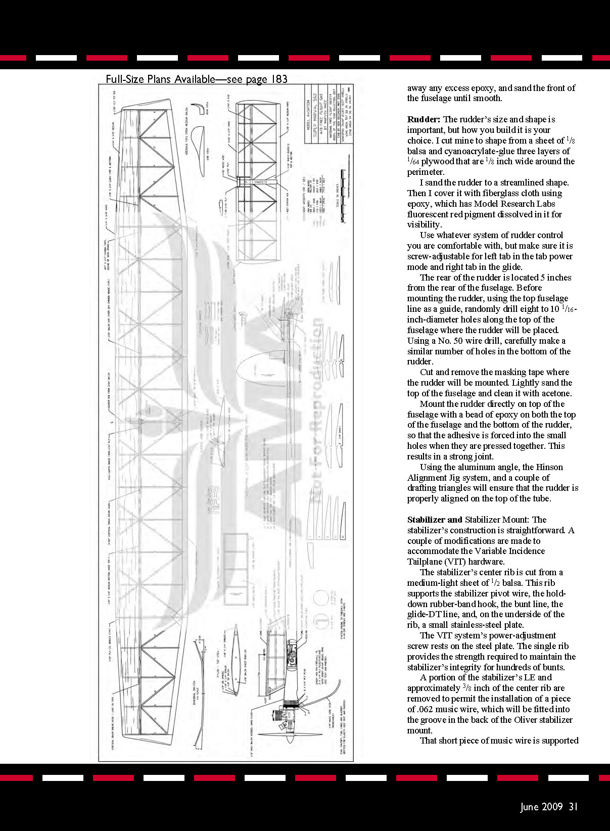
The Super Marval
An AMA 2007 Model of the Year
by Marvin Mace
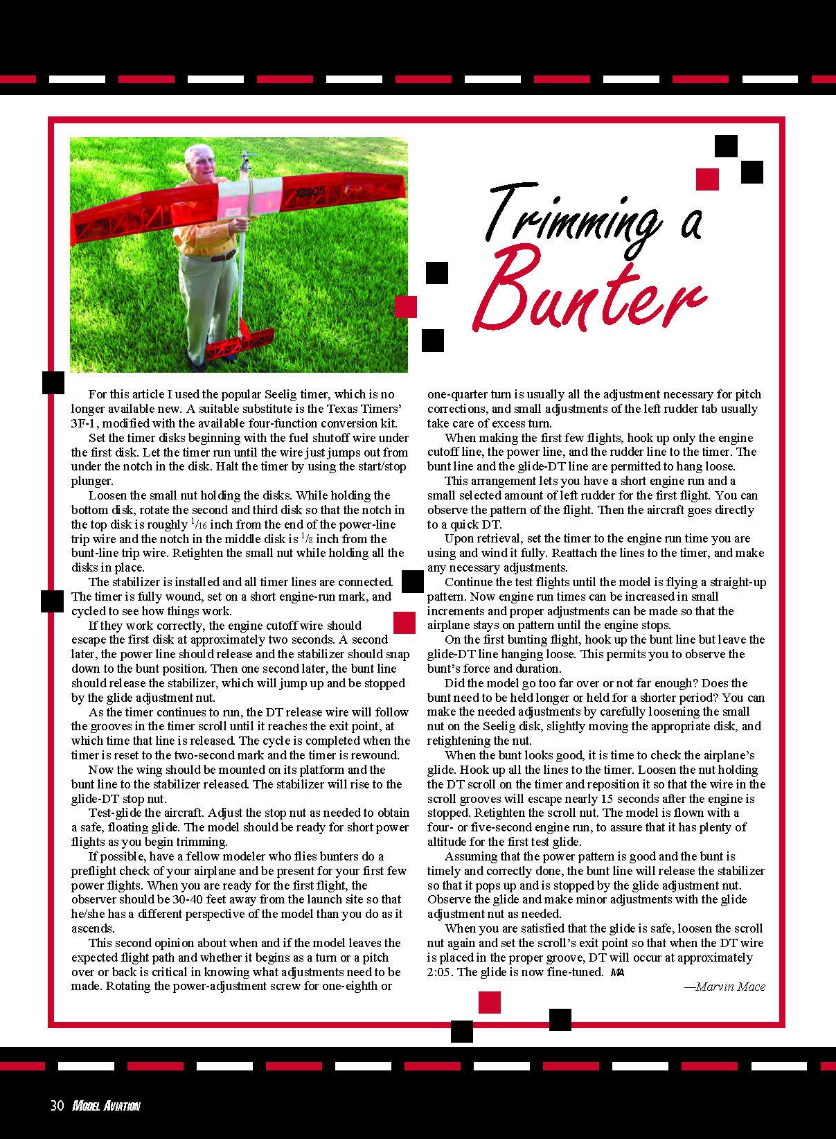
THE SUPER MARVAL is not a power model for beginners. It is a fairly sophisticated bunting airplane that can be easily built and flown by a modeler who has previously built and flown "locked-up" power models. If you make the investment of time and money to construct a Super Marval, you will have a model that, if well built and adjusted, is fun to fly and a competitive AMA Category III performer.
I hope your competitive attitude will encourage you to master the bunting technique. Perhaps the observations and confessions in this article will encourage you if you have reservations about taking the leap and sharing the challenge and joy a bunter offers. You probably won't be sorry if you do.
The use of a high‑strength, round, lightweight carbon‑fiber fuselage raises building issues that do not occur with an all‑balsa fuselage. For safety reasons, special construction provisions must be made to ensure the engine mounting's integrity in the carbon‑fiber fuselage.
There are several building tools you will find useful for working on this model:
- Scroll saw
- Drill press
- Electric hand drill
- Disc sander
- Dremel motor tool with a cutoff wheel
- 2‑56 tap and wrench
- 5‑foot‑long, 2‑inch aluminum 90° angle
CONSTRUCTION
Carbon-Fiber Fuselage Preparation
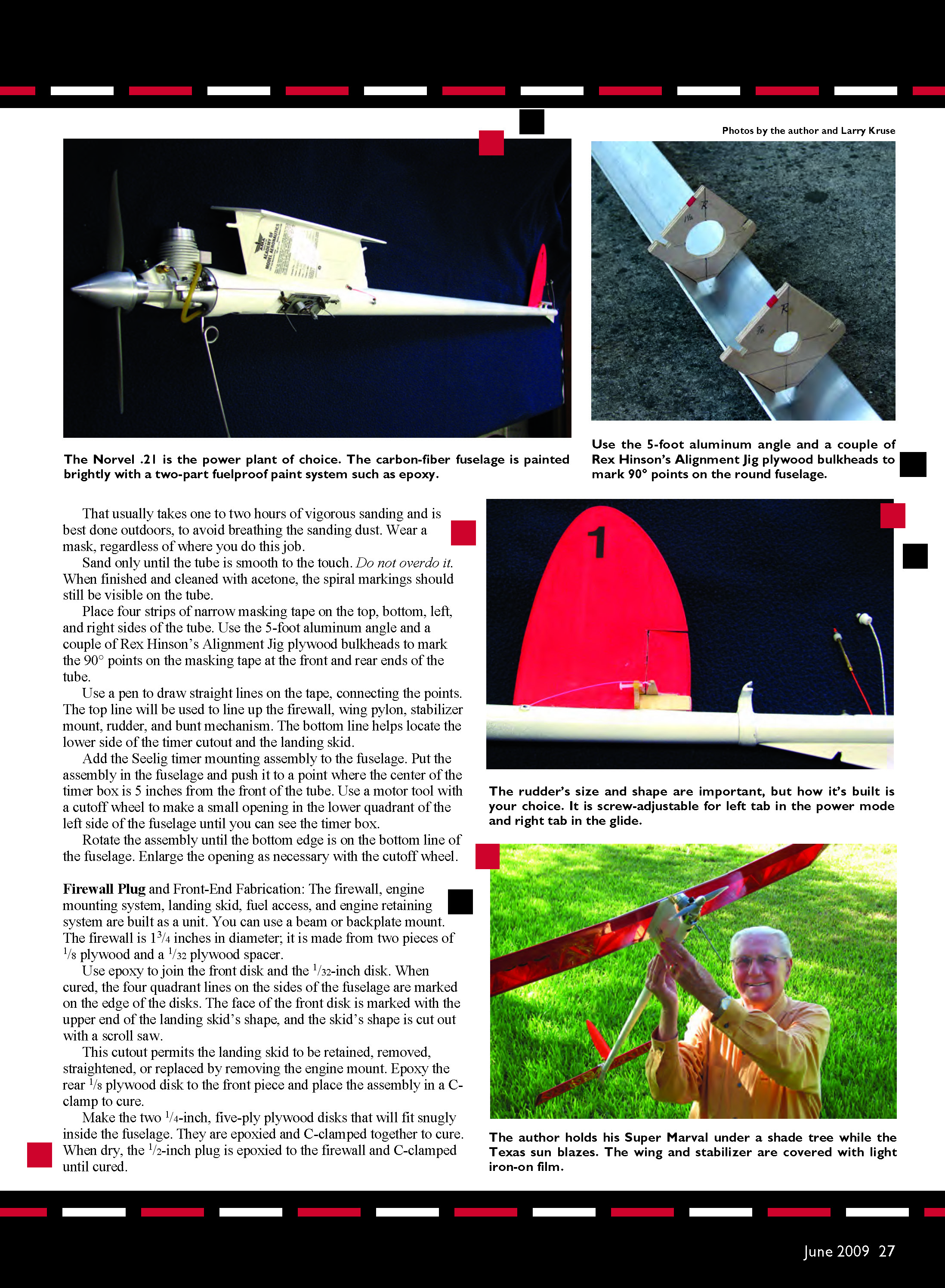
I chose a carbon‑fiber FIC tailboom, made by Hans Seelig in Germany, for the fuselage. As purchased, the tailboom is roughly 47.5 inches long and the outer surface is a spiral wrap that must be sanded smooth to the touch using 100‑grit sandpaper.
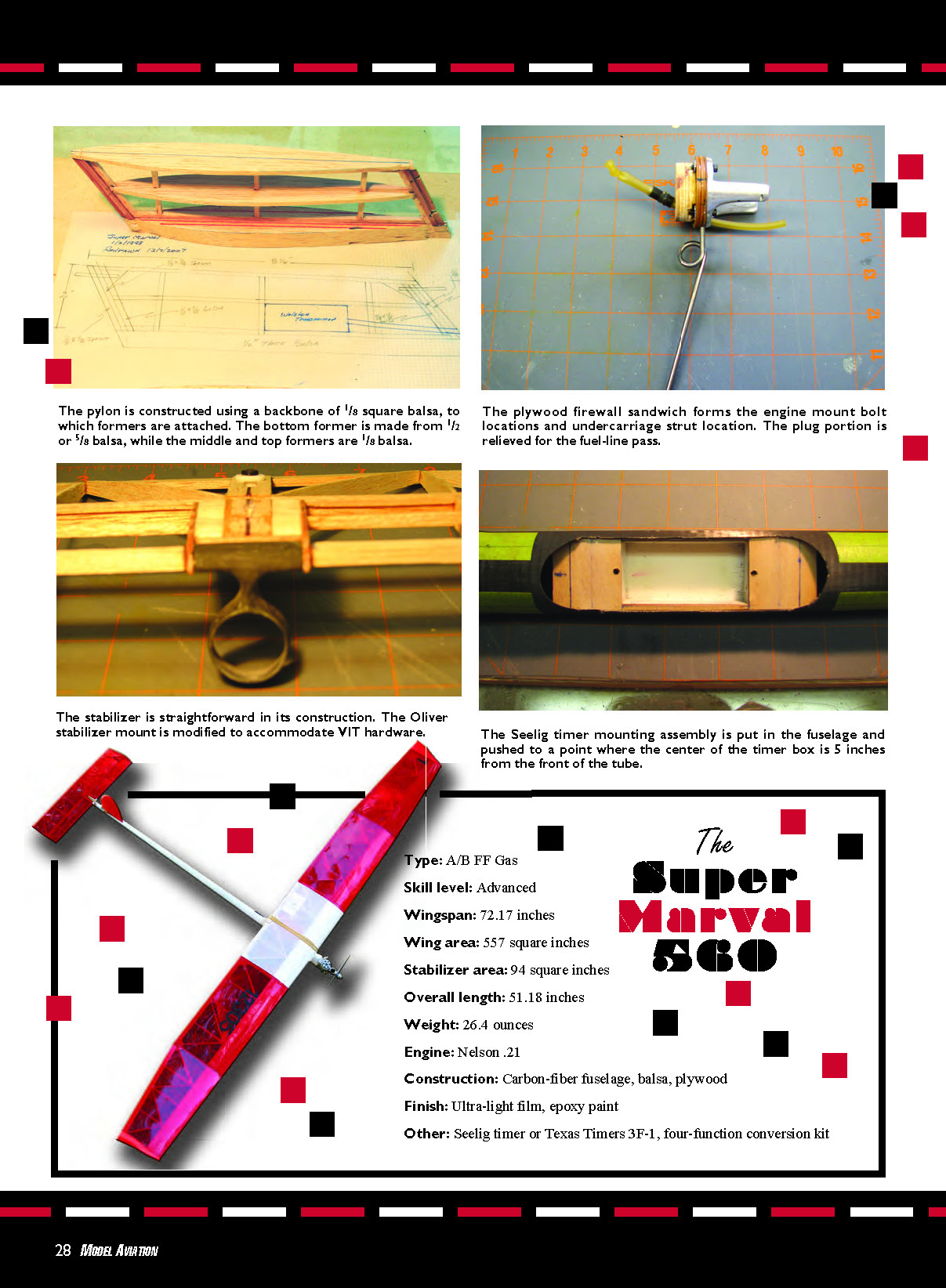
Use the 5‑foot aluminum angle and a couple of Rex Hinson's Alignment Jig plywood bulkheads to mark 90° points on the round fuselage. That usually takes one to two hours of vigorous sanding and is best done outdoors, to avoid breathing the sanding dust. Wear a mask, regardless of where you do this job. Sand only until the tube is smooth to the touch. Do not overdo it. When finished and cleaned with acetone, the spiral markings should still be visible on the tube.
Place four strips of narrow masking tape on the top, bottom, left, and right sides of the tube. Use the 5‑foot aluminum angle and a couple of Rex Hinson's Alignment Jig plywood bulkheads to mark the 90° points on the masking tape at the front and rear ends of the tube. Use a pen to draw straight lines on the tape, connecting the points. The top line will be used to line up the firewall, wing pylon, stabilizer mount, rudder, and bunt mechanism. The bottom line helps locate the lower side of the timer cutout and the landing skid.
Add the Seelig timer mounting assembly to the fuselage. Put the assembly in the fuselage and push it to a point where the center of the timer box is 5 inches from the front of the tube. Use a motor tool with a cutoff wheel to make a small opening in the lower quadrant of the left side of the fuselage until you can see the timer box. Rotate the assembly until the bottom edge is on the bottom line of the fuselage. Enlarge the opening as necessary with the cutoff wheel.
Firewall Plug and Front-End Fabrication
The firewall, engine mounting system, landing skid, fuel access, and engine retaining system are built as a unit. You can use a beam or backplate mount. The firewall is 1‑3/4 inches in diameter; it is made from two pieces of 1/8‑inch plywood and a 1/32‑inch plywood spacer. Use epoxy to join the front disk and the 1/32‑inch disk. When cured, mark the four quadrant lines on the edges of the disks to match the fuselage lines. Mark the face of the front disk with the upper end of the landing skid’s shape, and cut the skid’s shape out with a scroll saw.
This cutout permits the landing skid to be retained, removed, straightened, or replaced by removing the engine mount. Epoxy the rear 1/8 plywood disk to the front piece and place the assembly in a C‑clamp to cure.
Make the two 1/4‑inch, five‑ply plywood disks that will fit snugly inside the fuselage. Epoxy and C‑clamp them together to cure. When dry, epoxy the 1/2‑inch plug to the firewall and C‑clamp until cured.
Specifications
- Type: A/B FF Gas
- Skill level: Advanced
- Wingspan: 72.17 inches
- Wing area: 557 square inches
- Stabilizer area: 94 square inches
- Overall length: 51.18 inches
- Weight: 26.4 ounces
- Engine: Nelson .21
- Construction: Carbon‑fiber fuselage, balsa, plywood
- Finish: Ultra‑light film, epoxy paint
- Other: Seelig timer or Texas Timers 3F‑1, four‑function conversion kit
To ensure the integrity of the epoxy joint between the firewall and plug, mount a 4‑40 Phillips‑head bolt with washers and nut through both the firewall and plug (countersink both front and back). Tighten them so they cannot come apart.
Place the engine mount on the firewall, and put a drop of thin cyanoacrylate glue in the joint. Put the unit in a drill press and make the four mounting holes for the 4‑40 mounting bolts. After slightly countersinking the holes on the back of the firewall, install T‑nuts in the holes and tighten the 4‑40 bolts to seat them.
Place the firewall assembly in a machinist’s vise and drill a 1/4‑inch‑diameter hole at an angle from the lower left edge of the engine mount (near the landing skid) to a point near the center of the plug. This hole serves as access to the fuel compartment and fuel bladder.
You can separate the engine mount from the firewall by forcing a knife blade a short distance between the two.
Sand the front of the carbon‑fiber fuselage tube square to the thrustline. Carefully sand roughly an inch of the inside of the tube to remove any mold‑release residue and clean with acetone.
Brush epoxy onto the outside of the plug and the inside of the tube. Mate the two parts, taking care to line up the top and bottom marks of the firewall and tube.
After the epoxy has cured for at least 24 hours, carefully choose five or six points on the tube, roughly 1/4 inch behind the backside of the firewall, that will not interfere with previously installed hardware. Drill shallow 1/4‑inch‑diameter holes through the tube into the plug with a 13/64 bit.
Put a drop of epoxy in each drilled hole, and lightly drive a 3/8‑inch‑long, 13/64 dowel into the holes, leaving approximately 1/8 inch of the dowel sticking out above the tube. These dowels will pin the plug and firewall to the tube to assure that the engine is secure on the front of the tube.
To complete the front end, use cyanoacrylate to adhere small balsa wedges (approximately 1‑3/4 inches long and 1/4 inch high) to the nose of the tube, against the back of the firewall, and on each side of the dowels.
Fill spaces between the wedges with carpenter’s wood filler, and sand the front of the tube until smooth. Apply six to eight strips of fiberglass to the front end of the tube, and spread epoxy on the front 3 inches of the tube and the firewall.
Place a piece of waxed paper on the firewall. Attach the engine mount to the firewall using the 4‑40 bolts (coat the threads with a thick grease to prevent the epoxy from sticking to the bolts and the T‑nuts). Tighten the 4‑40 bolts and hang the fuselage nose‑down to cure.
When dry, remove the bolts, engine mount, and waxed paper.
For this article I used the popular Seelig timer, which is no longer available new. A suitable substitute is the Texas Timers’ 3F‑1, modified with the available four‑function conversion kit.
Set the timer disks beginning with the fuel shutoff wire under the first disk. Let the timer run until the wire just jumps out from under the notch in the disk. Halt the timer by using the start/stop plunger.
Loosen the small nut holding the disks. While holding the bottom disk, rotate the second and third disk so that the notch in the top disk is roughly 1/16 inch from the end of the power‑line trip wire and the notch in the middle disk is 1/8 inch from the bunt‑line trip wire. Retighten the small nut while holding all the disks in place.
With the stabilizer installed and all timer lines connected, fully wind the timer, set it on a short engine‑run mark, and cycle to see how things work.
If they work correctly, the engine cutoff wire should escape the first disk at approximately two seconds. A second later, the power line should release and the stabilizer should snap down to the bunt position. Then one second later, the bunt line should release the stabilizer, which will jump up and be stopped by the glide‑adjustment nut.
As the timer continues to run, the DT release wire will follow the grooves in the timer scroll until it reaches the exit point, at which time that line is released. The cycle is completed when the timer is reset to the two‑second mark and the timer is rewound.
Now mount the wing on its platform and release the bunt line to the stabilizer. The stabilizer will rise to the glide‑DT stop nut.
Test‑glide the aircraft. Adjust the stop nut as needed to obtain a safe, floating glide. The model should be ready for short power flights as you begin trimming.
If possible, have a fellow modeler who flies bunters do a preflight check of your airplane and be present for your first few power flights. When you are ready for the first flight, the observer should be 30–40 feet away from the launch site so that he or she has a different perspective of the model than you do as it ascends.
This second opinion about when and if the model leaves the expected flight path and whether it begins as a turn or a pitch over or back is critical in knowing what adjustments need to be made. Rotating the power‑adjustment screw one‑eighth or one‑quarter turn is usually all the adjustment necessary for pitch corrections, and small adjustments of the left rudder tab usually take care of excess turn.
When making the first few flights, hook up only the engine cutoff line, the power line, and the rudder line to the timer. The bunt line and the glide‑DT line are permitted to hang loose.
This arrangement gives you a short engine run and a small selected amount of left rudder for the first flight. You can observe the pattern of the flight, then the aircraft goes directly to a quick DT.
Upon retrieval, set the timer to the engine run time you are using and wind it fully. Reattach the lines to the timer, and make any necessary adjustments.
Continue the test flights until the model is flying a straight‑up pattern. Now engine run times can be increased in small increments and proper adjustments can be made so that the airplane stays on pattern until the engine stops.
On the first bunting flight, hook up the bunt line but leave the glide‑DT line hanging loose. This permits you to observe the bunt’s force and duration.
Did the model go too far over or not far enough? Does the bunt need to be held longer or for a shorter period? You can make the needed adjustments by carefully loosening the small nut on the Seelig disk, slightly moving the appropriate disk, and retightening the nut.
When the bunt looks good, it is time to check the airplane’s glide. Hook up all the lines to the timer. Loosen the nut holding the DT scroll on the timer and reposition it so that the wire in the scroll grooves will escape nearly 15 seconds after the engine is stopped. Retighten the scroll nut. Fly the model with a four‑ or five‑second engine run to ensure it has plenty of altitude for the first test glide.
Assuming the power pattern is good and the bunt is timely and correctly done, the bunt line will release the stabilizer so that it pops up and is stopped by the glide‑adjustment nut. Observe the glide and make minor adjustments with the glide‑adjustment nut as needed.
When you are satisfied that the glide is safe, loosen the scroll nut again and set the scroll’s exit point so that when the DT wire is placed in the proper groove, DT will occur at approximately 2:05. The glide is now fine‑tuned.
—Marvin Mace
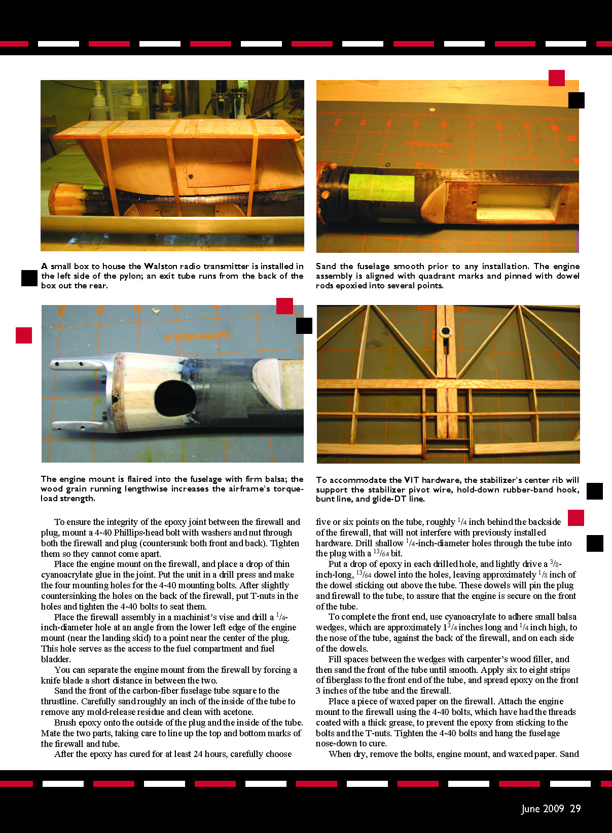
Rudder
The rudder’s size and shape are important, but how you build it is your choice. I cut mine to shape from a sheet of 1/8 balsa and cyanoacrylate‑glued three layers of 1/64 plywood that are 1/8 inch wide around the perimeter.
I sand the rudder to a streamlined shape. Then I cover it with fiberglass cloth using epoxy, which has Model Research Labs fluorescent red pigment dissolved in it for visibility.
Use whatever system of rudder control you are comfortable with, but make sure it is screw‑adjustable for left tab in the power mode and right tab in the glide.
The rear of the rudder is located 5 inches from the rear of the fuselage. Before mounting the rudder, using the top fuselage line as a guide, randomly drill eight to ten 1/16‑inch‑diameter holes along the top of the fuselage where the rudder will be placed. Using a No. 50 wire drill, carefully make a similar number of holes in the bottom of the rudder.
Cut and remove the masking tape where the rudder will be mounted. Lightly sand the top of the fuselage and clean it with acetone.
Mount the rudder directly on top of the fuselage with a bead of epoxy on both the top of the fuselage and the bottom of the rudder so that the adhesive is forced into the small holes when they are pressed together. This results in a strong joint.
Using the aluminum angle, the Hinson Alignment Jig system, and a couple of drafting triangles will ensure that the rudder is properly aligned on the top of the tube.
Stabilizer and Stabilizer Mount
The stabilizer’s construction is straightforward. A couple of modifications are made to accommodate the Variable Incidence Tailplane (VIT) hardware.
The stabilizer’s center rib is cut from a medium‑light sheet of 1/2 balsa. This rib supports the stabilizer pivot wire, the hold‑down rubber‑band hook, the bunt line, the glide‑DT line, and, on the underside of the rib, a small stainless‑steel plate.
The VIT system’s power‑adjustment screw rests on the steel plate. The single rib provides the strength required to maintain the stabilizer’s integrity for hundreds of bunts.
A portion of the stabilizer’s leading edge and approximately 3/8 inch of the center rib are removed to permit installation of a piece of .062 music wire, which will be fitted into the groove in the back of the Oliver stabilizer mount.
That short piece of music wire is supported in the stabilizer leading edge by 1/16 plywood half ribs and is tricky to install. When the half ribs are made, drill holes slightly larger than the .062 music wire in each of the two, approximately 1/8 inch from the front edge and centered top to bottom. Install the half ribs in the front part of the stabilizer, which has been cut to fit the Oliver stabilizer mount.
Sharpen a 1/2‑inch piece of .062 music wire and insert it into the half‑rib holes to increase the depth of the holes in the balsa leading edge. Cut another piece of .062 music wire to 1‑1/2 inches, and slightly sharpen both ends. Grasp this wire portion with pliers and ease one end a short distance into one of the holes in the half rib.
When the other end clears the opposite short rib, maneuver the other end into the opposite hole. The wire can be slid back and forth; put a drop of epoxy in each hole, center the wire, and set the stabilizer aside for the epoxy to cure.
Complete the stabilizer by making a cutout on the centerline of the thick rib for the glide‑DT post and the stabilizer capture button. Epoxy a small stainless‑steel plate, made from a razor blade, to the underside of the rib, just behind the stabilizer capture‑button hole.
Drill a small hole on the centerline of the wide rib, just behind the front spar, and epoxy a short piece of dowel in the hole to serve as a hook for the rubber bands that hold the stabilizer.
When you epoxy the stabilizer mount in position, be sure to put the stabilizer in its mount and place the fuselage tube in the aluminum angle so the stabilizer mount can be aligned 90° from the rudder. Use a bubble level on the stabilizer to ensure accurate positioning. The leading edge of the stabilizer mount should be located approximately 1 inch behind the rudder.
Ken Oliver makes a well‑constructed, efficient stabilizer mount, designed for bunting models. Judiciously sanding the mounting hole in the base will increase the inner diameter and provide a perfect fit on the tube.
The stabilizer mount’s exact location will be determined after the completed stabilizer is fitted on the fuselage with the VIT system in place. When positioned properly, the mount will be roughly 3‑1/2 inches from the end of the tube.
Lynch VIT Assembly
I like the VIT unit that Bill Lynch developed because it is located at the end of the fuselage and is trouble free when properly installed and rigged. It also permits visual inspection of important VIT system parts after you have attached the lines to the Seelig timer and before you fly the model. The information brochure Bill provides with his unit is invaluable when installing it and its lines.
Using the top line marked on the tube, use the cutoff wheel to make a slice nearly as long and wide as the top of the VIT frame (less the front tang). Use a small file to enlarge the cutout so the VIT frame fits.
It is necessary to mount a short piece of 3/32‑inch‑diameter aluminum tubing through the fuselage at a location so that the notch in the VIT frame will fit perfectly on the tubing when the short tang bolt is tightened.
To determine where the holes for the 3/32 tubing are located on the sides of the fuselage, start with your best guess, use a tiny drill bit, and enlarge the holes in the proper direction until the tubing is a perfect fit in the notch of the VIT unit. When you find the proper location, install the 3/32 tubing (slightly longer than the fuselage is wide) and epoxy it in place (both on the inside and outside of the fuselage).
When cured, slip the VIT frame into position with the notch over the 3/32 aluminum tube. Drill a small hole in the top of the fuselage, matching the hole in the tang.
Screw a 1/4‑inch‑long 2‑56 bolt (with a small flat washer and a lock washer) through the hole in the top of the tube and into the hole in the tang of the frame so the frame is held firmly in place when the bolt is tightened.
Wing
The balsa D‑box wing spans 72 inches and is constructed in five panels. The main spar is an I‑beam with 1/4 x .007 carbon‑fiber strips on the insides of the 1/4 x 1/8 balsa spar caps.
Flight Preparation
Before heading to the flying field for the first test flight, it is mandatory that you check the model in the shop for decalage. To do this, draw a 48‑inch straight line on the workbench. Lay the fuselage on its side with its centerline located precisely on the straight line. Draw a line on the workbench from the front to the back of the wing platform.
Go to the back of the fuselage and make a dot on the workbench that corresponds with the wire groove of the Oliver stabilizer mount. Using a drafting triangle pressed against the top of the workbench, make a mark indicating the top of that screw.
Go to the front of the fuselage and make a mark that corresponds with the top of the timer box. Draw a straight line between the marks. Draw a line on the workbench from the front to the back of the wing platform.
Now lay the wing on the bench with the bottom of the wing platform flat on the table and centered on the bench line so that the fuselage centerline is parallel to the bench line. Using an accurate ruler, measure the distance from the top of the table to the front and rear of the wing platform.
If the front is roughly 1/8 inch higher than the rear, you are home free. If not, continue the back‑and‑forth sanding, with pressure applied as needed, until the platform incidence is 1/8 inch. With the correct wing incidence, the model can be assembled and the final pylon location determined.
Make a permanent mark on the edge of the platform at 58% of the wing chord. Install the engine, propeller, spinner, wire skid, timer, and radio transmitter. The wing with the pylon and stabilizer are attached to the fuselage with rubber bands.
Balance the model at 58% of the wing chord by sliding the wing pylon back and forth on the tube until a balance point is found and the fuselage is parallel to the floor. Mark the masking tape on the top line of the fuselage where the front and back of the pylon are. Randomly drill a series of small holes along the top line of the fuselage between the marks, and drill several small holes in the bottom of the pylon.
Remove the masking tape where the pylon is to be located. Lightly sand the top of the tube and clean it with acetone. Coat the top of the fuselage and the bottom of the pylon with epoxy, and join them. As with the rudder, the adhesive will be forced into the small drilled holes, improving the joint strength.
Use three or four strong rubber bands to hold the pylon tightly to the fuselage, then place the assembly in the aluminum angle. Line up the pylon with the remaining top line marks on the fuselage and with the rudder while using a bubble level on the top of the wing platform. When everything is properly aligned, allow the epoxy to cure for 24 hours.
Accurately measure the distance between the front and back of the wing platform to the fuselage centerline, and measure from the two dots that represent the distance from the front and back of the stabilizer to the centerline. The difference between the measurements represents the model’s decalage.
Recall that we built 1/8 inch of incidence into the wing platform when we mounted it on the fuselage. Since we would like to start trimming with 1/16 inch of decalage, we can adjust the power‑adjustment screw up or down as needed to achieve this 1/16 difference.
You should be ready to trim your Super Marval for competition. Repeatable, safe engine runs are extremely important—especially at four and five seconds. The penalty for overruns during flyoffs is a zero time, and nothing could be worse. Err on the side of a safe engine run.
Keep your timer clean and oiled and all of your model’s parts in perfect shape and in good working order. Have confidence in your timer and your ability to accurately set it for any engine run.
That confidence comes from making many test flights with the help of fellow modelers who know how to accurately time an engine run. The watch starts when the aircraft leaves the flier’s hand and ends when you hear the engine’s last audible power stroke.
I take this opportunity to acknowledge the invaluable help and advice I have received from my fellow bunters in the past few years as I have tried to get up to speed. Insights or clever ideas that I appear to claim as my own are the result of conversations I have had with guys such as Doug Galbreath, Bill Lynch, Ken Oliver, the late Bob Johannes, Dick Covalt, Bob Mattes, Gil Robbins, Ronnie Thompson, Don DeLoach, Faust Parker, Henry Spence, Mark Troutman, Reid and Roger Simpson, C. C. Johnson, and Dick Hall.
I also thank Larry Kruse for helping me put this construction article together in a format for publication. The Super Marval is as much your model as it is mine. MA
Marvin Mace 107 Country Ln. Seguin, TX 78155 (830) 379‑0036 [email protected]
Sources
- Seelig carbon‑fiber tube:
Reid C. Simpson 115 Trail Ridge Dr. Athens, TX 75751 (903) 677‑8525 [email protected]
- Oliver stabilizer mount:
Ken Oliver 2213 El Cejo Cir. Rancho Cordova, CA 95670 (916) 363‑2017
- Lynch VIT system:
Bill Lynch 2279 Auburn Ravine Dr. Lincoln, CA 95648 (916) 645‑3337 [email protected]
- Alignment Jig:
Rex Hinson 1141 S. Waterview Dr. Inverness, FL 34450 (352) 344‑5931 [email protected]
- Red fluorescent pigment:
Model Research Labs / Curt Stevens 25108 Marguerite Parkway #160 Mission Viejo, CA 92692 [email protected]
- Walston Retrieval Systems:
Jim Walston 725 Coopers Lake Rd. SE Smyrna, GA 30082 (770) 434‑4905 [email protected]
- Texas Timers (request model 3F1 and four‑function conversion kit):
3317 Pine Timbers Dr. Johnson City, TN 37604 (423) 282‑6423 www.texastimers.com
Transcribed from original scans by AI. Minor OCR errors may remain.

