
Super Sportwin
A sleek twin-motor electric that is built for speed
by Mark Rittinger
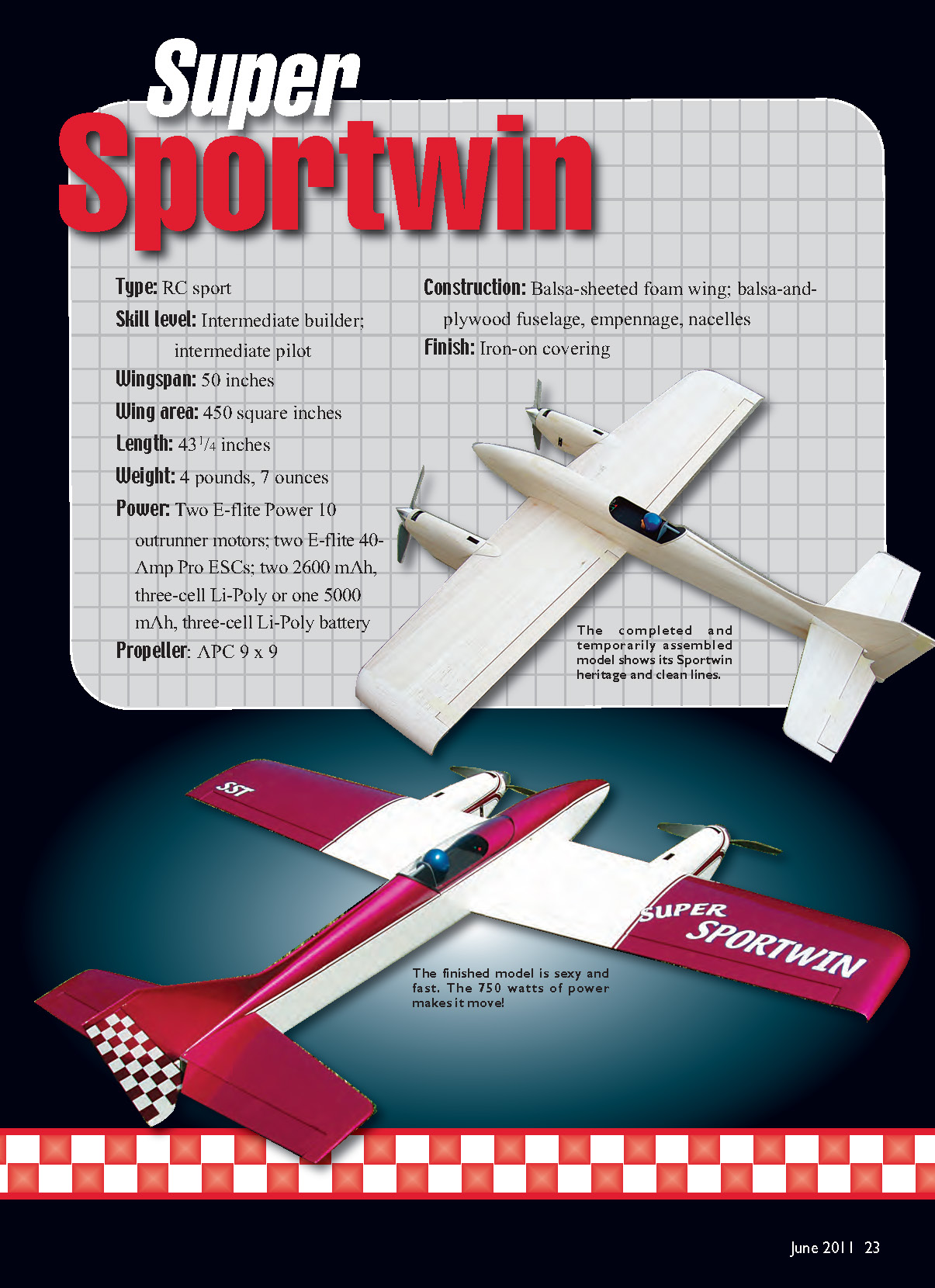
- Type: RC sport
- Skill level: Intermediate builder; intermediate pilot
- Wingspan: 50 inches
- Wing area: 450 square inches
- Length: 43-1/4 inches
- Weight: 4 pounds, 7 ounces
- Power: Two E-flite Power 10 outrunner motors; two E-flite 40-Amp Pro ESCs; two 2600 mAh, 3-cell Li‑Poly batteries or one 5000 mAh, 3-cell Li‑Poly battery
- Propeller: APC 9 x 9
- Construction: Balsa-sheeted foam wing; balsa-and-plywood fuselage, empennage, nacelles
- Finish: Iron-on covering
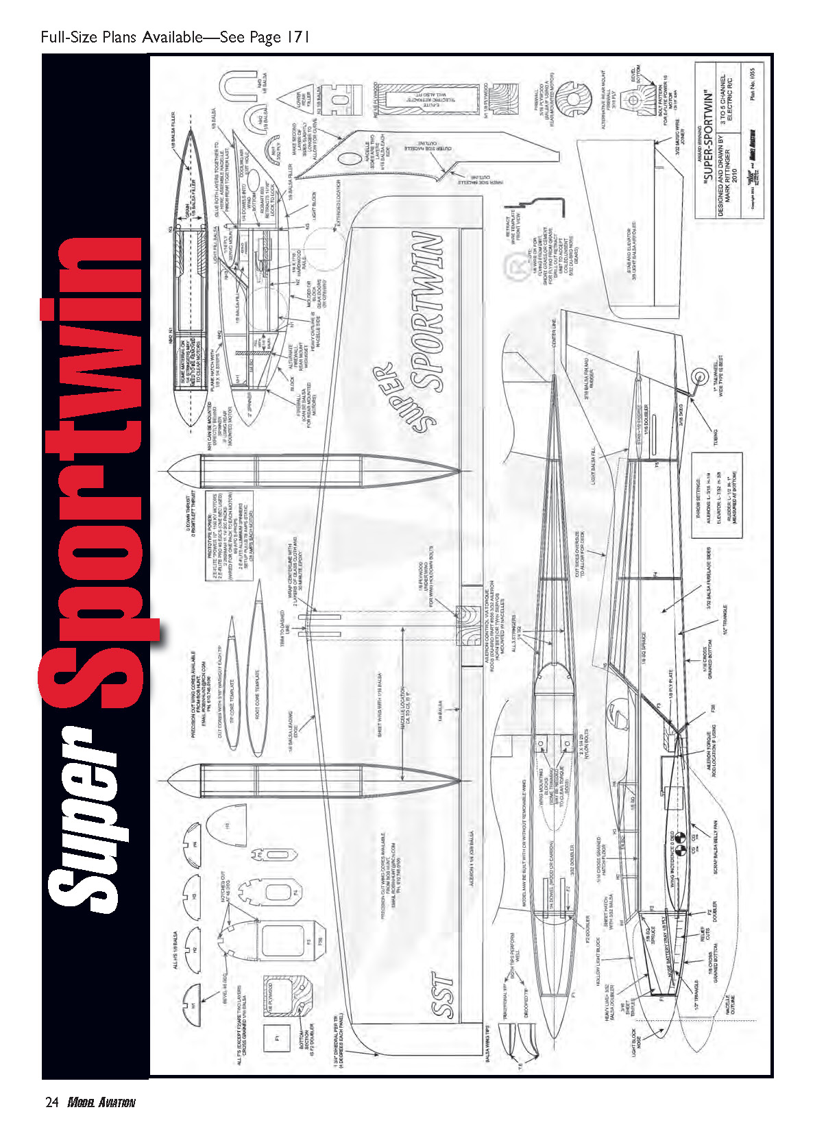
Full-Size Plans Available—See Page 171
In 2001, at the height of the "Speed 400" craze, I designed my original Sportwin. Spanning 38 inches with simple, all-balsa construction, it was an instant hit. Many Sportwins were built around the world, and it gained quite a following as a fun, fast, quick-building, slick little electric twin. This model shocked (no pun intended!) many people with its great handling and good performance on the meager power that was available at the time.
Brushless motors came into vogue shortly after, and they were soon followed by Li-Poly batteries. Both of those developments were major leaps forward in power-plant design for electric models. No longer was it necessary to watch every gram; an abundance of power was at your service. Numerous Sportwins were built with brushless and Li-Poly power, and some were extremely quick.
Not long after the design hit, I was asked to design a larger model with a landing gear or possibly retractable undercarriage. I was busy designing scale aircraft, so I kept pushing the request back, waiting for the right time. During the summer of 2009 I saw Denny Sumner flying a Sportwin at the Mid‑America Electric Flies meet, and that reminded me what a great little design it was. The bug bit me again—and hard. I sat down and drew the Super Sportwin a few days later. I competed at the 2010 Toledo Weak Signals R/C Show with the new "SST." It placed second in the Sport Plane category, 30 years after my dad won the now‑defunct 1/2A category.
This is not merely a scaled-up rendering of the Sportwin. It's an entirely new model, designed from the ground up, using the general shapes of the Speed 400 version. There are many differences. The SST wing is made from foam and removable, the airfoil is semi-symmetrical, the tail is longer, the stabilizer is larger, it has retracts, a rudder, and 1 horsepower (about 750 watts) hauls it around the big blue!
Although this is not a beginner’s model in the sense of construction or flying, anyone who has scratch-built an airplane should have no problems with it. My designs feature hidden right angles or straight lines that might not be readily apparent. I have arranged for Bob Hunt, of CL Aerobatics fame, to make wing cores available, and they are perfect. Robart and E-flite retracts fit in the nacelles with minor trimming.
So if you are still interested, let’s get building!
CONSTRUCTION
Fuselage
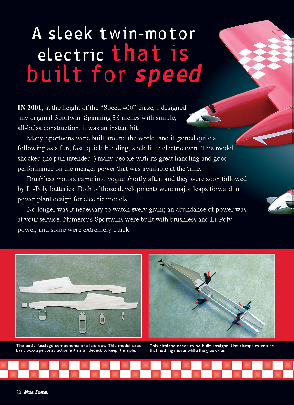
This part of the SST is fairly straightforward; it’s a basic box type with a turtledeck. All wood dimensions are inches.
- Cut matching sides from medium 3/32 balsa. Cut the top turtledeck section oversize to allow for the curvature.
- Add the 1/8 square spruce stringer, 3/32 balsa doubler from wing TE to nose, and 1/2 triangle stock along the bottom front and rear of the fuselage. Glue in the stabilizer mount doubler and small 3/16 sheet tripler in the nose.
- Slice F2 from 1/8 plywood, and glue on the 1/8 square spruce and F2 doubler (also from 1/8 plywood). Glue to left side as shown on the plans.
- Cut F3 and F3B from two layers of cross‑grain 1/16 balsa. Pay attention to the 45° angle of the notches. Glue to the left fuselage side against the doubler.
- Carefully line up the left and right sides, and adhere them at F2 and F3. Using the top view, glue the tail together.
- Cut F1 from layered 1/16 balsa and glue in place in the nose. The fuselage side doubler should stop 1/8 inch from the nose to allow for fitment of F1. Slide F4 and F5 into place and glue. Install the three 1/4 square rear-deck stringers.
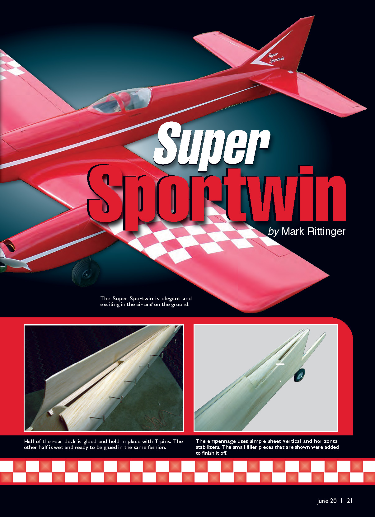
- Wet one fuselage side on the turtledeck with hot water on the outside only, and it will begin to bend toward the center stringer. Mark the center and cut to size. Glue to the top and side stringer and repeat for the other side.
- Sheet the bottom rear section with 1/16 balsa. Cut to rough shape and glue on the top nose block and nose. Do not sheet the lower nose at this time.
- Add the hardwood wing hold-down blocks and 1/8 plywood plates.
- Build the hatch directly on top of the fuselage. Using 1/16 with grain running side to side, lay the hatch floor. Sand to match the sides of the fuselage. Glue on the 1/8 square, H1 through H5, triangle braces, and stringers. Plank or sheet the hatch with 3/32 balsa. On the underside of the hatch, you can add hatch-alignment aids from scrap balsa, magnet hold-downs, or rubber band hooks.
- Sand everything to be ultraslick, and set aside to work on the wing.
Wing
This is a simple foam affair, sheeted with 1/16 balsa, using a single aileron servo. I’ve grown tired of seeing ugly servos sticking out all over pretty models, so take a few extra minutes to make a clean aileron-servo installation.
- Using the templates on the plans, cut the cores with 3/16 inch of washout per tip or order them from Bob Hunt. Lightly sand the cores to remove the cutting fuzz.
- Assemble the core sheeting from 48-inch-long sheets of matched 1/16 balsa (I used six pieces of 3 x 48 x 1/16). Cut the core sheeting slightly oversized using the core as a template. Spray the sheeting with a light coat of plain hair spray to aid adhesion.
- To sheet the foam I used finishing resin and made a “wing press” from two 24-inch-square pieces of 1 1/2-inch-thick hardwood. I drilled six holes through and inserted threaded rods. Spread a thin coat of resin on the cores, place them in their beds with the sheeting, and put them in the press. Tightening the nuts put even, firm pressure on the cores until dry (approximately six hours). If you have a flat workbench and heavy weights, that will work just as well. Other glues such as wood glue, contact cements, and epoxy will also work to sheet the wings. The key is a true surface; uneven, warped wings perform poorly.
- After the wings are sheeted, add the 1/4 hard balsa leading edge and the 1/8 balsa rear cap. Sand to shape. Sand the root to match 4° (1 3/4 inches) per panel dihedral, and epoxy them together, ensuring that they are aligned.
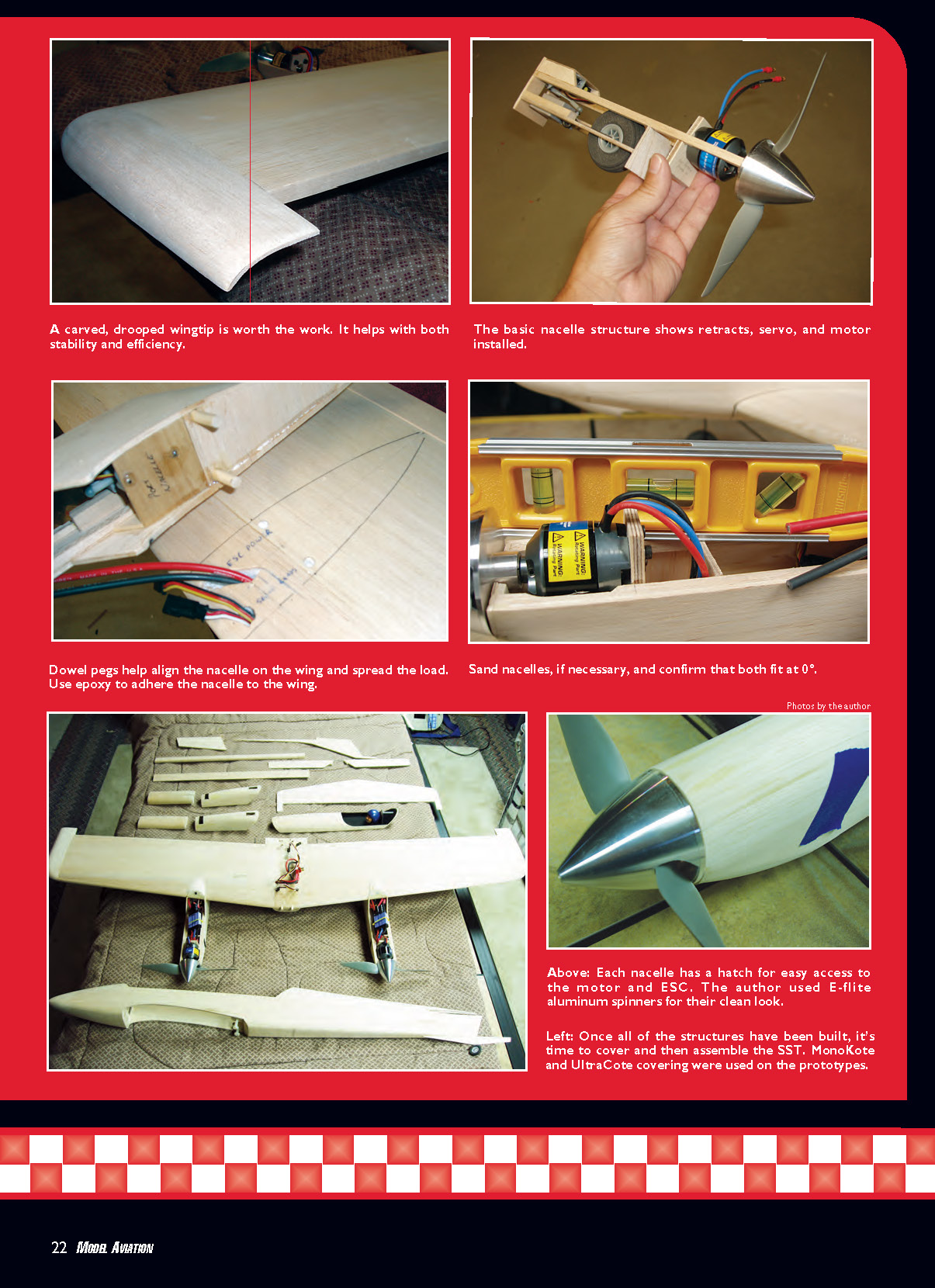
- Decide on the wingtip shape you will use, and add them to the tips. Add the center TE section, plywood wing mount, and torque rods. Cut the hole for the aileron servo. Sand the LE flat to match the opening in the fuselage, and sand the wing to perfectly fit the fuselage opening. Cut ailerons to fit, and drill holes for the torque rods. I used floppy-disk material for hinges, after covering.
- Mark locations for the ESC, retract (if used), and power wires to run through the wing from the center fuselage area to the nacelles. Use an X‑Acto knife to slice a "V" in the sheeting where the wires will run. Run the motor power wires approximately 1 inch or more from the ESC signal wires, and twist the positive and negative power wires to reduce radio-frequency interference issues. Remove the foam from the V-piece cut from the wing, install the wires, and glue the piece back on. Wrap the center section with two layers of fiberglass or nylon cloth and 30-minute epoxy.
- Carefully align the wing in the fuselage, and clamp in place. Use a long 1/4-inch drill to make a hole through F2 and its doubler into the wing for two wing-alignment dowels. Screw an old nylon wing screw, ground to a point, through from inside the fuselage to mark the wing hold-down-screw locations. Remove the clamps, and install two 1/4-inch dowels in the wing with epoxy. Drill holes through the wing for the nylon screws. Attach the wing to the fuselage and double-check alignment. It should be straight and fit tight to the fuselage. If it isn't, find out what is off and adjust it.
- Build, from scrap balsa, the lower center-section under the wing, and sand it to fit. You can also sheet the lower fuselage nose and sand it to a nice contour—something similar to a cross between a P-38 and a de Havilland Comet.
Empennage
The SST uses simple sheet vertical and horizontal stabilizers.
- Cut the horizontal stabilizer from 3/8 balsa, add the tips, and sand to an airfoil shape as shown.
- Cut the elevators from 1/4 balsa, and taper to match the stabilizer. Make a joiner from 3/32 music or piano wire, and fit to the elevator halves.
- Using an incidence meter, set the wing to 0°, make it immobile with weights or sandbags, and sand the fuselage to get -1/2° in the stabilizer.
- Cut the fin, rudder, dorsal, and skeg from 3/16 balsa, and sand to fit the fuselage. The fin is glued to the top of the fuselage and the top of the stabilizer, and small filler pieces are added to finish it. I do not install the fin and stabilizer until after covering; I find it much easier to cover this way.
- The tail wheel wire runs through a tube and into the fin. Denny built the second prototype and elected to make the rudder run all the way to the bottom of the model; you can do that too.
Nacelles
The nacelles are built around a frame of plywood and balsa. Use aircraft-grade plywood in this area; light plywood won't hold up.
- Decide what motors you will use and what type of retracts, if any. This model can be simplified significantly by making it hand-launchable with fixed gear. Firewall location and servo/retract location are much easier to adjust now than later.
- If you plan on employing inrunner motors, use a 3/16 plywood front-mount firewall. For rear-mounted outrunner types, use the rear 3/16 plywood firewall. A solid firewall is essential for reducing rpm-robbing vibration.
- Cut N1 and N2 from 1/8 plywood. Make the opening on the rear of N2 the required size to clear the retracts. The plans fit the Robart 600 series. Epoxy N1 to N2 and add N3, made from 1/8 balsa. These are right-angle pieces. Add the maple or spruce hardwood retract bearing rails. Glue on the 1/4 stringers and the nose firewall. The 1/4 square stringers can be used as datum.
- If you're using the rear firewall, cut it from 3/16 plywood. Depending on your motors, you can move it forward or rearward and it is still on the datum thrustline. You might need to trim or add slightly to the firewall bottom to fit in place. Mark and drill for the motor mounts and epoxy in place.
- Fit the retract servo, or retract unit if using electric units. Bend the legs to match the plans or to fit your application. Test operation now rather than later. I used mini ball links with metal-gear servos to operate the retracts.
- The inner and outer referred to on the nacelle sides relates to wing orientation; inner is toward the root and outer is toward the tip. Cut an "inner" and an "outer" side from 1/16 balsa and glue on each side. Cut a second side of each, and glue to the nacelles back to N3, but no farther than that, giving you 1/8-inch-thick nacelle sides. Glue the 1/8 top and bottom fillers in place.
- Wet the rear sides of the nacelles, and pin or clamp together along the rear edge. Let dry and then remove pins and glue together. That's how you make 1/8-inch wood bend that tight; do it in layers. Add the lower front and rear blocks, and make the gear doors or center filler block with retract gear hole. I initially made clamshell gear doors, but after much fuss I decided that holes to clear the gear were much simpler and lighter. Denny made removable pieces, with dowels and magnets to hold them on. This way he can still remove them for maintenance. Add the 1/4-inch-diameter dowels that go up into the wing cores.
- Build the hatches directly on the nacelles by gluing NH1, NH2, and NH3 on top of two strips of 1/8 x 1/4 balsa and planking with 1/8 x 1/4 balsa strips. I used clothing snaps in the front and a magnet on the rear to hold them in place. You might find that the hatches are easier to install after the nacelles are glued to the wing. Repeat construction for the second nacelle, being sure not to build two left or right ones!
Final Assembly/Covering
- If you stand the wing on its TE, you can mark 9 inches from the centerline of the wing to each nacelle centerline, and mark them with a triangle on the wing bottom sheeting. Mark the holes and drill for the 1/4-inch-diameter dowels in the nacelles. Fit all wiring through the nacelle opening, and trial-fit the nacelles. Use an incidence meter and/or levels and dry-fit and sand for perfect fitment.
- Epoxy the nacelles to the wing bottom. Use a long triangle or measure 18 inches from center to center at the front and at the rear to ensure alignment. A good-performing model must be assembled straight—trimming in the air can correct for only so much.
- Trial-fit the fin/rudder and double-check to make sure that the stabilizer has -1/2°. Cover the SST at this point. I used white and Metallic Wine MonoKote on mine, and Denny used red UltraCote. I strongly suggest employing a vibrant color scheme with large panels of bright colors; it makes this aircraft much easier to see in the air.
- After covering, hinge the surfaces using pieces cut from floppy-disk material. I use thin CA to adhere them in place and have yet to have one break. Glue on the stabilizer, making sure that it's aligned, and then glue on the fin with the dorsal. Glue on the canopy. I used a Great Planes Spirit glider unit, trimmed to fit.
Equipment Installation
I am using a Hitec Eclipse 7 radio system with a 2.4 GHz module, also from Hitec. This combo has worked flawlessly, with no interference from any of the wiring or motors.
- Radio setup: one aileron servo (HS-65MG) with torque rods, one elevator servo (HS-82MG), one rudder servo (HS-82MG), and retract servos in the nacelles. I mounted the rudder and elevator servos directly behind the wing, on hardwood rails. The receiver is mounted on the fuselage side with double-stick tape.
- Make pushrods using 1/4 spruce and threaded ends. For the best in precision, you can use ball links on the pushrods.
- Powerplant: My SST has 750 watts of power on tap from two incredibly reliable E-flite Power 10 1100 Kv motors. I also equipped it with 9 x 9 APC propellers and E-flite aluminum spinners. Mount your motors to the firewall, and hook up the ESCs. I used E-flite 40-Amp Pro heat-sinked speed controllers and one BEC, by disconnecting the red wire on one of the ESCs. These are capable of handling up to seven servos each. You can use a separate BEC if you prefer.
- Batteries: I've been flying with two 2600 mAh, 11.1-volt 30C Li‑Poly packs—one for each individual ESC. You can set yours up this way or, as Denny has done, with one 5000 mAh, 11.1-volt pack powering both ESCs. Whatever you choose, make sure that the battery and the connector(s) can handle the amperage draw. Use hook-and-loop fastener to hold your battery in place, and make sure that it has adequate cooling air going over it.
Balance and Control Throws
- Balance at the forward point shown on the plans for the model's first flights, then move it rearward. Don't go past 33% or it gets a bit twitchy.
Initial control throws:
- Low rates:
- Aileron: 3/16" up/down
- Elevator: 1/4" up/down
- Rudder: 1/2" left/right (at bottom)
- High rates:
- Aileron: 1/4" up/down
- Elevator: 3/8" up/down
- Rudder: 1" left/right (at bottom)
Flying As you always should, double- and triple-check the throws on low and high rates and the proper direction of surface travel. You might prefer to add exponential. Have a buddy hold the model at least a foot off the ground and do a motor-running range check. Never skip this step! Just because you have 2.4 GHz capability does not mean there might not be issues.
If everything seems good to go, install fully charged batteries and get a feeling for the SST's ground handling. A few degrees of toe-in on the main gear helps greatly. Line up the airplane into the wind and smoothly apply power. You'll find that it likes heavy right rudder until the tail lifts, and then you can let off slightly. I use high-rate rudder until flying and then switch to low.
Once the aircraft is up on the mains, apply more power and it will smoothly lift off. Gain some altitude and trim it out. Test the stall and glide ratio. You'll see that the SST is fast and glides well. Line up for landing with a lot of ground in front of it to allow for that flat, fast glide.
Once back on the ground, give it a thorough examination. Make sure that there are no loose parts or equipment. Now you can take this model up and wring it out! Put a fresh pack or packs in and go up again. You can do all of the RC Aerobatics (Pattern) moves with it and outrun some glow racers. The SST tracks like a Pattern model with the speed of a racer. Huge loops and vertical moves are easy, and this airplane will do well inverted with some practice. It also does good four-point rolls and slow rolls.
I hope you enjoy your Super Sportwin as much as I do! I'll bet you'll turn a few heads at the flying field and swell with pride when flying it.
MA
Mark Rittinger [email protected]
Sources:
- Bob Hunt — (610) 746-0106; [email protected]
- E-flite — (800) 338-4639; www.e-flite.com
- Hitec RCD — (858) 748-6948; www.hitecrcd.com
- APC — (530) 661-0399; www.apcprop.com
- Robart — (630) 584-7616; www.robart.com
Transcribed from original scans by AI. Minor OCR errors may remain.

