
Support Your Local Engine
by Frank Granelli
Introduction
Last month I wrote about four-stroke model engines and compared their many design—but few operational—differences from two-stroke engines. Throughout this series I have covered starting, maintaining, and getting the most from your engine as you run it, but in the real world, model engines require support equipment to operate. I took this for granted in previous installments; this month I'll cover onboard and fueling equipment.
Onboard Fuel Tanks
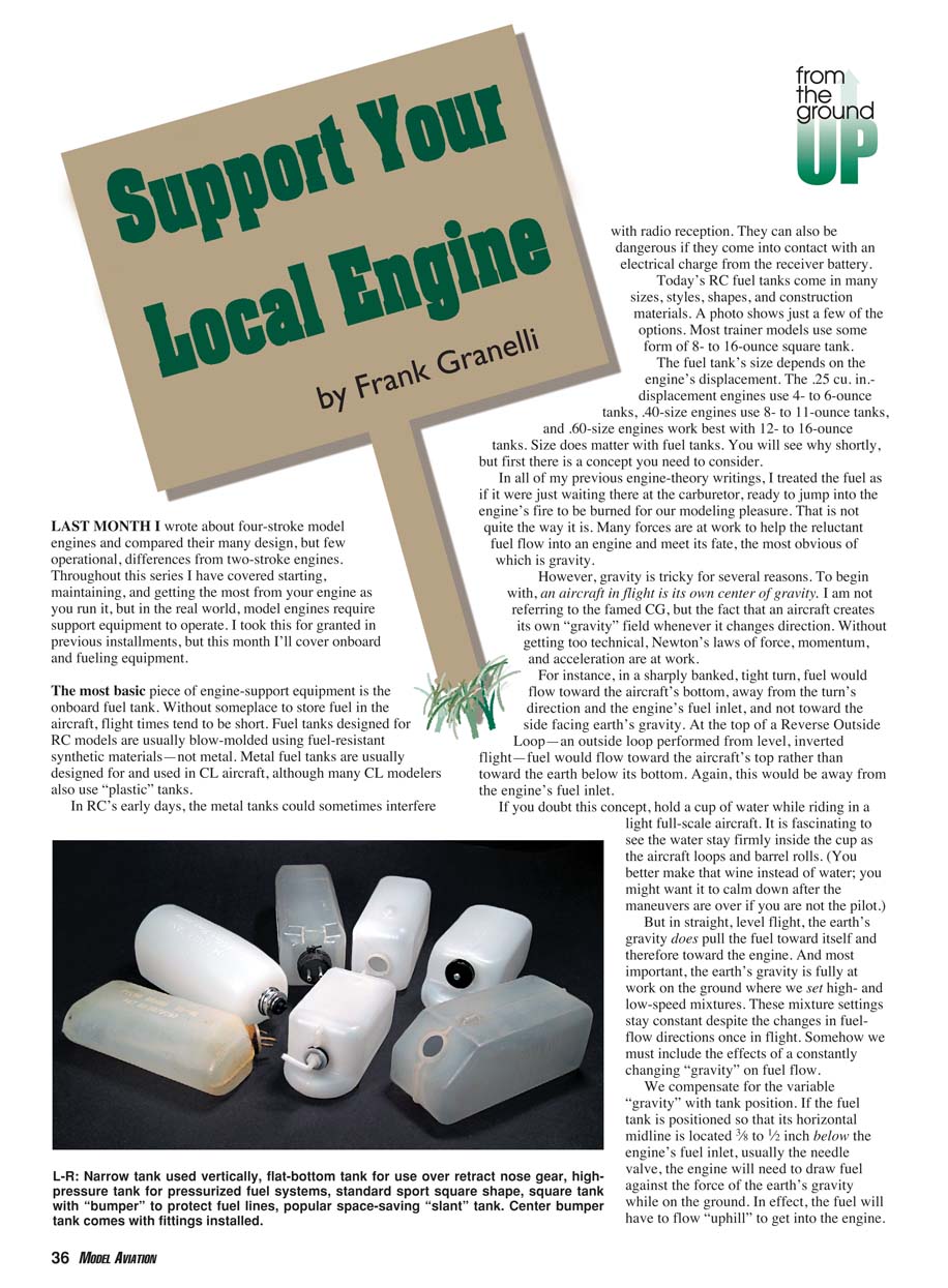
The most basic piece of engine-support equipment is the onboard fuel tank. Without someplace to store fuel in the aircraft, flight times tend to be short. Fuel tanks designed for RC models are usually blow-molded from fuel-resistant synthetic materials—not metal. Metal fuel tanks are usually designed for and used in CL aircraft, although many CL modelers also use plastic tanks.
In RC's early days, metal tanks could sometimes interfere with radio reception. They can also be dangerous if they come into contact with an electrical charge from the receiver battery.
Today's RC fuel tanks come in many sizes, styles, shapes, and construction materials. Most trainer models use some form of 8- to 16-ounce square tank.
Tank Size Recommendations
Tank size depends on the engine's displacement. A general guideline:
- .25 cu. in. engines: 4–6 ounce tanks
- .40-size engines: 8–11 ounce tanks
- .60-size engines: 12–16 ounce tanks
Size matters because of several forces that affect fuel flow; you'll see why shortly.
Tank Position and Gravity Effects
In earlier engine-theory writings I treated fuel as if it were just waiting at the carburetor, ready to be burned. That's not quite the case. Many forces act on fuel to get it into the engine; the most obvious is gravity. However, gravity is tricky because an aircraft in flight creates its own effective "gravity" whenever it changes direction. Newton's laws of force, momentum, and acceleration are at work.
For example, in a sharply banked, tight turn, fuel will flow toward the aircraft's bottom—away from the turn's direction and possibly away from the engine's fuel inlet. At the top of a reverse outside loop (an outside loop performed from level, inverted flight), fuel will flow toward the aircraft's top rather than toward the earth below its bottom, again possibly away from the engine's inlet. If you doubt this, hold a cup of water while riding in a light full-scale aircraft — the water stays firmly in the cup through loops and rolls.
In straight, level flight, earth's gravity does pull the fuel down toward the engine. More importantly, earth's gravity is fully at work on the ground where we set high- and low-speed mixtures. These mixture settings stay constant despite the changes in fuel-flow direction once in flight. To compensate for the variable effective gravity in flight, we must position the tank so that the engine will draw fuel against earth gravity while on the ground.
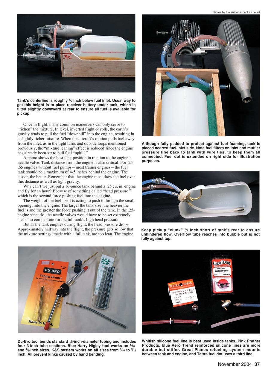
The recommended placement is to position the fuel tank so its horizontal midline is about 3/8 to 1/2 inch below the engine's fuel inlet (usually the needle valve). This makes the engine draw fuel "uphill" on the ground. Once in flight, many common maneuvers tend to richen the mixture as gravity or maneuver forces pull fuel "downhill" into the engine. When the aircraft's motion pulls fuel away from the inlet (tight turns, outside loops), the tendency to richen is reduced because the engine was already set to pull fuel uphill.
Tank Distance, Head Pressure, and Muffler Pressure
Tank distance from the engine is also critical. For .25–.65 engines without fuel pumps (most trainer engines), the fuel tank should be a maximum of 4–5 inches behind the engine. The closer, the better—the engine must draw fuel over this distance as well as fight gravity.
Head pressure is the second force pushing fuel into the engine: the weight of fuel in the tank presses fuel through the pickup into the engine. Larger tanks have greater head pressure. For a small .25 engine, a full 16-ounce tank would create high head pressure, requiring extremely lean needle settings to compensate. As the tank empties, head pressure drops, and mixtures set with a full tank can become too lean halfway through the flight, causing the engine to die during a climb or high-G maneuver. You could set the mixtures extra rich initially to compensate, but that would make the early part of the flight underpowered.
Muffler pressure is the third force affecting fuel flow. The engine pumps exhaust pressure into the tank via a muffler pressure/overflow line, and that pressure helps keep flow rates more consistent during steep climbs and high-G maneuvers. Muffler pressure, however, is relatively constant based on engine speed; it does not increase to compensate for long-term reductions in head pressure as the tank empties. Muffler pressure is more effective during brief maneuvers than in compensating for the decreasing head pressure over the duration of the flight.
Engine designers take muffler pressure into account when sizing carburetor air inlets—allowing larger air inlets for more power because muffler pressure helps feed additional fuel into the carburetor.
Tank Plumbing and Pickup Lines
A few practical plumbing details are worth mentioning:
- The tank's fuel-outlet line should be roughly the same height as the engine's fuel inlet. Run the fuel line as directly as possible to the inlet without going far downhill and then back up. Excessive "uphill" runs near empty can cause the engine to quit. If your engine quits before the tank is empty, check for this roller-coaster condition.
- The tank is not centered directly behind the engine; its outlet is positioned slightly toward the side with the needle valve. This reduces uphill/downhill effects no matter which direction the aircraft banks or rolls.
- If possible, mount the tank inside a thin foam layer to reduce bubbling caused by engine vibration.
If the engine is tightly cowled or the fuel line cannot be easily disconnected for refueling, use a third line to the fuel tank—a fill line. This fill line must be blocked after filling to prevent muffler-pressure loss during operation. Common blocking methods include the simple "fuel dot" cap, or commercially available filler valves (for example, the Great Planes Fuel Filler Valve), which allow the engine line to remain short and direct while providing a convenient fill port. If a filler valve leaves an unused port, block it with a short piece of fuel line capped with a small 4-40 bolt.
Inside the tank, position plumbing so the muffler-pressure/overflow brass tubing sits inside any bubble section for maximum capacity. Keep the pickup line run as straight as possible to prevent it from wrapping around vent tubing and being stuck in a forward position, which could starve the engine during some maneuvers. Some modelers use rigid plastic tubing on the pickup line to prevent fouling, but rigid tubing can prevent fuel flow during long vertical dives or spins. Choose based on your plane and flying style.
When filling, squeeze the filling line while installing a fuel-dot cap or quickly close your filler system to prevent spilling once the pump line is removed.
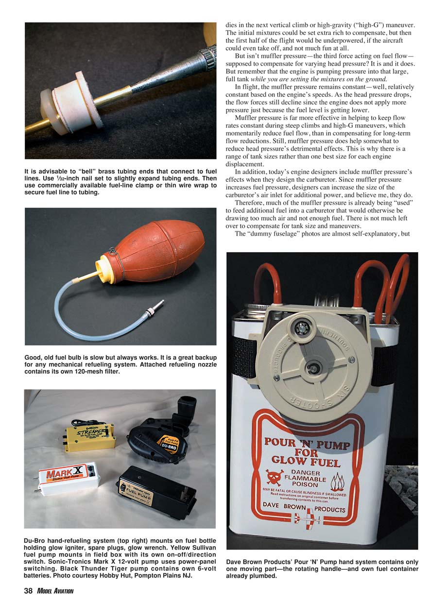
Bending brass tubing is easy but avoid kinking. Tubing benders prevent kinks and provide the needed angles. If you accidentally kink tubing, carefully apply pressure with pliers to round the spot and restore operation if a spare tube is not available.
Fuel Line Types and Sizes
Some flexible tubing—called fuel line—is required to connect the tank's brass tubing to the engine, muffler, and fill port. Two types are commonly used today:
- Pure silicone fuel line: semi-clear, extremely flexible, fuelproof, and unaffected by model fuel. It lasts virtually forever inside the tank without stiffening or degrading. However, it can crack or suffer rubbing wear outside the tank and is prone to slipping off brass tubing if not secured properly.
- Reinforced silicone fuel line: retains the fuelproof benefits of pure silicone but is resistant to cracking and vibration wear and tends to stay connected. It is preferred for external runs.
Fuel-line size recommendations:
- Small-diameter line: good up to .25 cu. in. engines
- Medium-diameter line: good up to .65 cu. in. engines
- Large-diameter line: for engines larger than .65 cu. in.
A practical rule: compare the engine's inlet diameter (inside measurement) at the high-speed needle valve to the inside diameter of the fuel line and try to match them. A slightly larger-diameter line is preferable to a smaller one if you can't match perfectly. Make sure the fuel line grips the engine inlet firmly and won't slip off.
Filters
The fuel filter is not optional—use a good filter or expect problems. Competition fliers have proven this repeatedly. Despite filtering fuel through increasingly fine screens during refueling (for example, from 100-mesh down to 250-mesh), onboard fuel filters still collect alcohol-insoluble material and must be cleaned regularly—typically every 200 flights for pump-equipped engines and every 200–300 flights for non-pumped engines. I clean the filters in my competition aircraft every 200 flights or they begin to clog. Paint thinner removes the residue inside the filters. If onboard filters didn't catch this material, it would eventually clog carburetor sections or pump parts.
Also install a second filter in the muffler-pressure line between the muffler and the fuel tank to limit the amount of junk the engine blows back into the tank. Make sure filters are tight to prevent air leaks, and clean refueling-system filters more often than onboard filters because refueling filters may serve multiple aircraft.
Refueling Equipment
With the tank installed and plumbed, you still need to get fuel into it. Several refueling methods are in common use:
- Squeeze bulbs or turkey-baster–style fillers: inexpensive, slow, and useful as backups in the field.
- Hand pumps: some fit on the plastic fuel jug and use a hand-crank to pump fuel in or out.
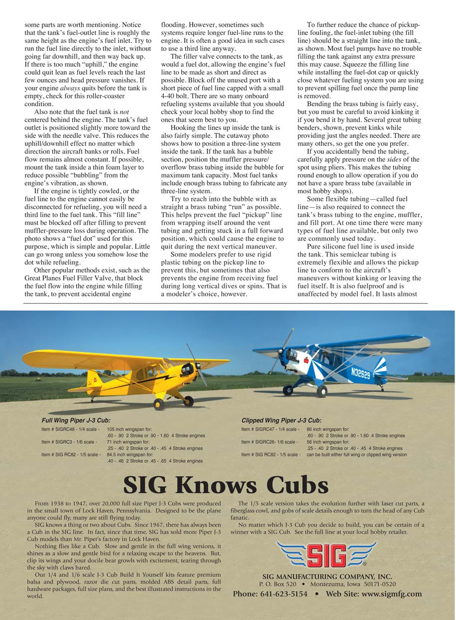
- Integrated refueling systems: combine container and pump (examples include Du-Bro and Dave Brown's Pump-N-Go). Some systems also hold glow-plug igniters and spare parts.
- Electric pumps: attach directly to the fuel container or are part of a field-box system; many use 12 V field-box batteries or include their own batteries. Some units have their own on/off/directional switches; others use the field box power panel switch.
Use reinforced silicone line for refueling plumbing. Many electric-pump manufacturers recommend larger-diameter fuel line to reduce pump wear; you can use a short piece of medium line over the filling nozzle with the large line over that assembly. Clean refueling-system filters more frequently than onboard filters.
Run-Up and What's Next
Once the aircraft is fueled and ready to go, you still need to turn the engine over, light the glow plug, and hold the model in place safely during run-up and trimming.
Next month, the final installment of the engine segment will cover field boxes, batteries, starters, glow-plug igniters, and chicken sticks.
Frank Granelli 24 Old Middletown Rd. Rockaway, NJ 07866
Transcribed from original scans by AI. Minor OCR errors may remain.

