
Airtronics VG6000 Radio System
Bob Aberle E-mail: [email protected]
Highlights
- Six-channel-function FM system.
- Four-model memory positions (numbered only; cannot name models).
- Simple-to-use single menu that is visible on the LCD screen at all times.
- Comes with full Ni-Cd battery packs and a dual-output charger.
- Includes four servos.
- Control features: dual rate and exponential (expo) rate on elevator and aileron, end point adjust (EPA), servo reversing, and a variety of mixing functions.
- Trim is auto-saved in each memory position; trim position is displayed graphically on the LCD screen.
- Battery icon gauge, low-voltage alarm, and voltage readout available on the screen.
- Timer function provided; can count up or down and display on the LCD screen.
- Instruction manual available in PDF format on Airtronics' website.
- Current street price: $179.95.
My February 2004 contribution to the Model Aviation "From the Ground Up" beginners’ series was "Advanced Radio Control Systems." The idea was to introduce beginners to the next step up in RC equipment—computer-driven radio systems. In that article I mentioned the new Airtronics VG6000 RC system; in this review I explore it in depth.
The VG6000 is simple to operate and inexpensive (under $200), yet offers many extra features compared to a basic system. You can selectively employ the added features as you gain experience in the RC hobby.
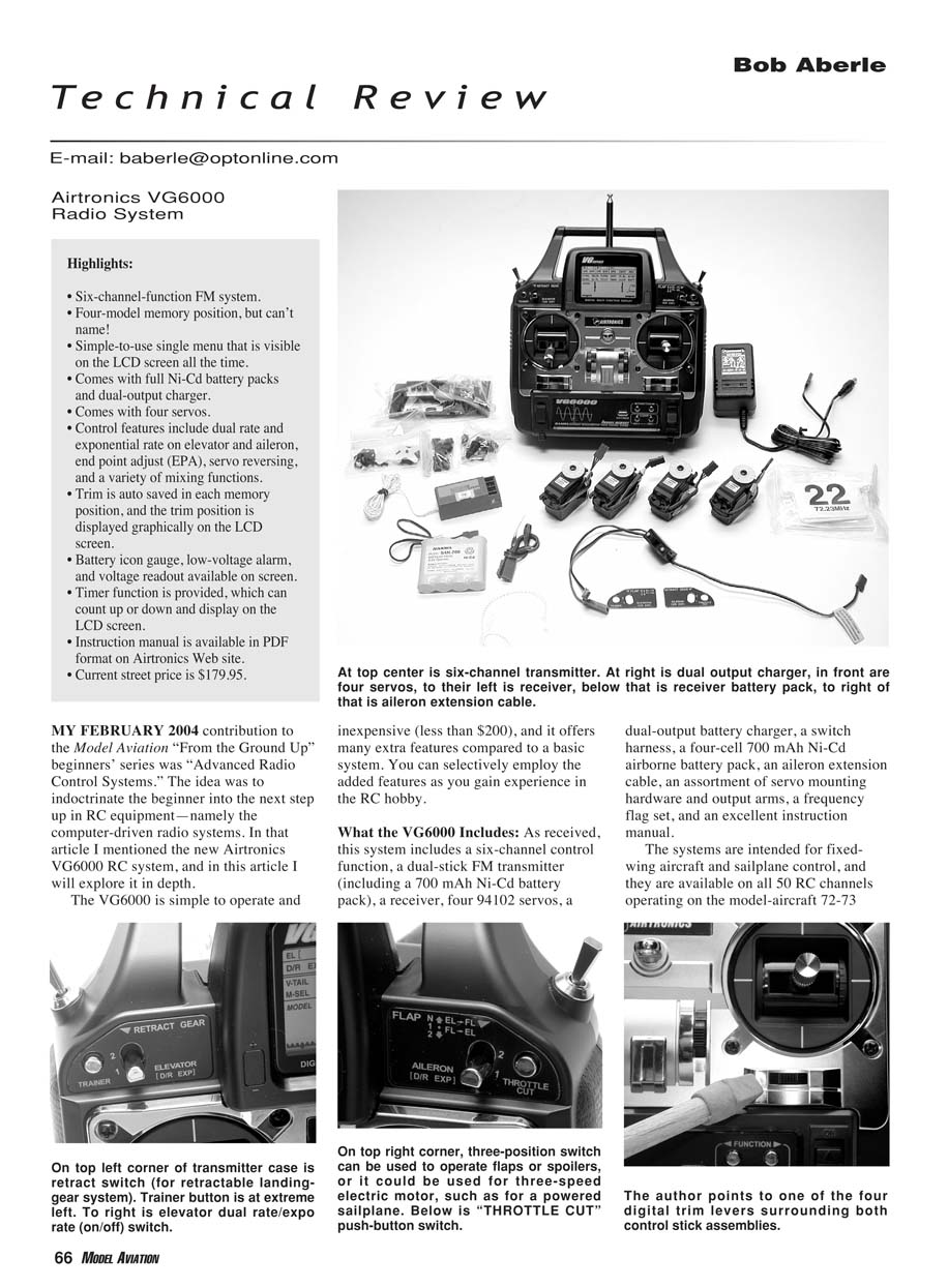
What the VG6000 Includes
- Six-channel control-function, dual-stick FM transmitter (includes 700 mAh Ni-Cd battery pack).
- Receiver (model 92777 FM receiver; 1.1 oz; dual-conversion circuitry).
- Four 94102 servos (standard servo: 1.5 oz; claimed 42 in/oz torque).
- Dual-output battery charger.
- Switch harness.
- Four-cell 700 mAh Ni-Cd airborne battery pack (same Sanyo cells as the transmitter).
- Aileron extension cable.
- Assortment of servo mounting hardware and output arms.
- Frequency flag set.
- Instruction manual (23 pages, PDF available online).
The system is intended for fixed-wing aircraft and sailplane control and is available on all 50 RC channels operating on the model-aircraft 72–73 MHz band. Airtronics FM systems operate with deviation on the high side; they are compatible with JR receivers but may not be compatible with other brands. The connectors are Airtronics "Z" type with the positive pin in the center, which is compatible with most other systems on the market. Older-style Airtronics connectors (more than eight years old) require a special adapter to operate with the newer "Z"-type connectors.
VG6000 Transmitter
The VG6000's heart is a computer-driven, six-channel transmitter. It provides four model memory positions, but positions are numbered only (1–4), so you must identify models by number.
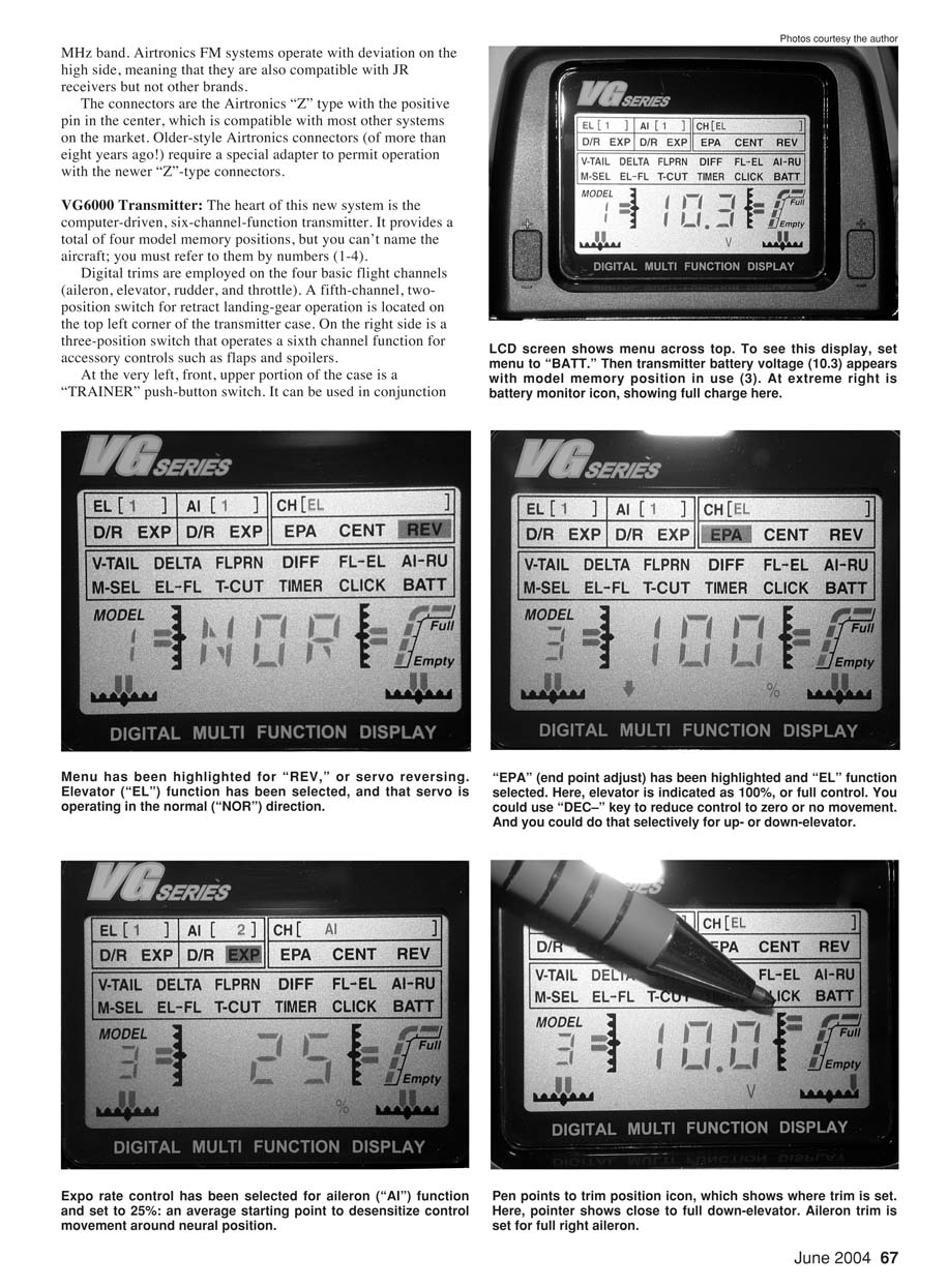
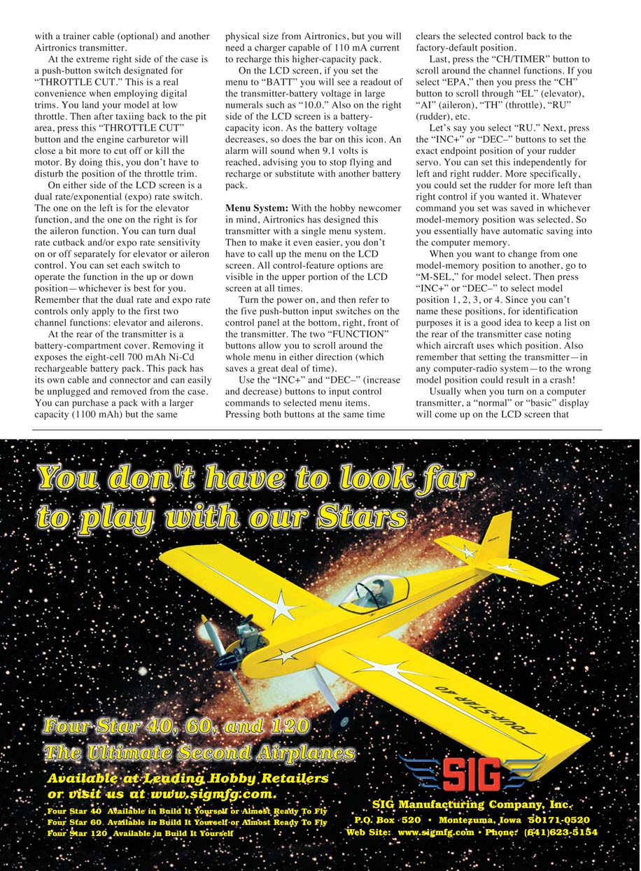
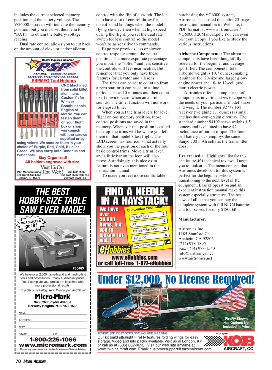
Digital trims are employed on the four basic flight channels (aileron, elevator, rudder, and throttle). A fifth-channel, two-position switch for retract landing-gear operation is located on the top left corner of the transmitter case. On the right side is a three-position switch that operates a sixth-channel function for accessories such as flaps or spoilers.
At the very left front upper portion of the case is a "TRAINER" push-button switch. It can be used with an optional trainer cable and another Airtronics transmitter.
At the extreme right side of the case is a "THROTTLE CUT" push-button switch. This is convenient when employing digital trims: after landing and taxiing back to the pit area, press the "THROTTLE CUT" button to close the engine carburetor slightly and cut the motor, without disturbing the throttle-trim position.
On either side of the LCD screen are dual rate/exponential (expo) switches. The left one controls elevator, and the right one controls aileron. Dual rate cutback and/or expo sensitivity can be turned on or off separately for elevator or aileron. Each switch can be set to operate the function in the up or down position—whichever you prefer. Note that dual rate and expo apply only to elevator and ailerons.
At the rear of the transmitter is a battery-compartment cover. Removing it exposes the eight-cell 700 mAh Ni-Cd rechargeable battery pack, which has its own cable and connector and can be unplugged and removed. You can purchase a larger-capacity pack (1100 mAh) with the same physical size from Airtronics, but you will need a charger capable of 110 mA to recharge the higher-capacity pack.
On the LCD screen, if you set the menu to "BATT" you will see a readout of the transmitter-battery voltage in large numerals (for example, "10.0"). Also on the right side of the LCD screen is a battery-capacity icon; as battery voltage decreases, the bar on this icon decreases. An alarm sounds when 9.1 volts is reached, advising you to stop flying and recharge or replace the battery pack.
Menu System
With the hobby newcomer in mind, Airtronics designed this transmitter with a single, easy menu system. All control-feature options are visible in the upper portion of the LCD screen at all times, so you do not have to call up a separate menu.
Turn the power on, then use the five push-button input switches on the control panel at the bottom-right front of the transmitter:
- Two "FUNCTION" buttons allow you to scroll through the menu in either direction.
- "INC+" and "DEC-" buttons increase or decrease selected menu values. Pressing both at the same time clears the selected control back to the factory-default position.
- The "CH/TIMER" button scrolls around channel functions and timer settings.
If you select "EPA" then press "CH" (channel) to scroll through "EL" (elevator), "AI" (aileron), "TH" (throttle), "RU" (rudder), etc. For example, select "RU" and then press "INC+" or "DEC-" to set the exact endpoint position of your rudder servo. Endpoints can be set independently for left and right travel. Whatever command you set is saved in the currently selected model-memory position (automatic saving).
To change model-memory positions, go to "M-SEL" (model select) and press "INC+" or "DEC-" to select position 1, 2, 3, or 4. Because you cannot name positions, keep a list on the rear of the transmitter case noting which aircraft uses which position. Remember that setting the transmitter to the wrong model position could result in a crash.
Usually, when you turn on a computer transmitter, a "normal" or "basic" display appears showing the selected memory position and battery voltage. The VG6000 indicates the memory position on its default screen, but you must set the menu to "BATT" to view the battery-voltage reading.
Dual rate control allows you to reduce the amount of elevator and/or aileron throw with the flip of a switch. Use full throws for takeoff and landing (low-speed flight) and reduced throws for high-speed flight to make the model less sensitive. Expo provides reduced control response around neutral; higher expo percentages make the controls feel "softer" near neutral. These features apply only to elevator and ailerons.
The timer can count up from zero or be set to a countdown time (for example, 10 minutes) and will sound an alarm at zero. The timer cannot be used as an elapsed-time meter.
Trim positions are saved per memory position. When you set trim levers for level flight on one model-memory position, those positions are stored and recalled when you select that model. The LCD screen has four icons that show the position of each of the four basic control trims; moving a trim lever moves a corresponding bar on the icon. This feature is not mentioned in the instruction manual but is a useful visual aid.
Airtronics has posted the entire 23-page instruction manual for the VG6000 on its website in PDF format: www.airtronics.net/VG6000%20Manual.pdf. You can print a copy if you prefer a paper manual.
Airborne Components
The airborne components have been thoughtfully selected for the beginner and average sport flier. The total airborne weight is 10.7 ounces, making it suitable for .20-size and larger glow-engine models and 10- to 12-cell (and more) electric power installations.
Airtronics offers component sets in various sizes to match your model's needs. The number 92777 FM receiver (1.1 oz) uses dual-conversion circuitry. The standard 94102 servo (1.5 oz) is claimed to provide 42 in/oz of torque. The four-cell battery pack uses Sanyo 700 mAh cells.
I have created the Highlights list for this and future Model Aviation technical reviews. Airtronics' development for this system is well suited for beginners transitioning to the next level of RC equipment: ease of operation and an excellent instruction manual make the VG6000 especially attractive. The best news is that you can buy the complete system with full Ni-Cd batteries and four servos for around $180. MA
Manufacturer
Airtronics Inc. 1185 Stanford Ct. Anaheim, CA 92805 (714) 978-1895 Fax: (714) 978-1540 [email protected] www.airtronics.net
Transcribed from original scans by AI. Minor OCR errors may remain.

