
Texan II
by Bob Isaacks
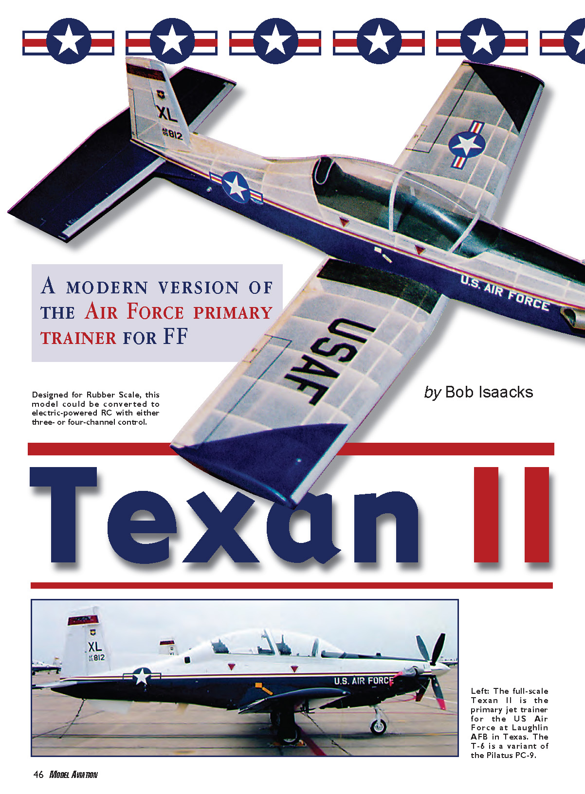
Rubber scale modelers are always in search of the “perfect subject.” The modeled airplane must be charismatic, well documented, and, most important, possess good areas and moments to assure successful flight performance. Additionally, the aircraft must offer some promise of ease of construction as the plans are developed. The Raytheon/Beechcraft Texan II, a turbo‑powered trainer, is currently in use by the US Air Force and meets all of these requirements.
I live in Katy, Texas, and own a ranch near Del Rio, Texas, home of the 47th Flying Training Wing at Laughlin Air Force Base. Texan IIs are constantly in the air around Del Rio, and I have spent several hours watching the sleek trainers shoot approaches and practice touch‑and‑gos at Laughlin. I made contact with Captain Ken Hall, chief of public affairs at Laughlin, and Kent Cummings, chief of community and media relations, who allowed me to take photos of a Texan II on the flightline for authentication of the model I’m presenting in this article. My thanks to the personnel at Laughlin—especially Carl Riordan, T‑6 maintenance work leader, and Mark Escobar, aircraft sign painter—who were very cooperative in helping me obtain some details that are not currently available on the Internet.
The Texan II is a development/redesign of the Pilatus PC‑9, a trainer that several countries currently use. With slight modifications to the fins and canopy framing, the model in this feature can be built as a PC‑9. A Google search will yield a myriad of mouthwatering PC‑9 color schemes that beg to be replicated on a model. While researching the Texan II, I found references indicating that the Pilatus is a direct descendant of the Arado Ar.96, a German World War II trainer. My last article in Model Aviation (Dec 2005) was about an Ar.96. The design similarities are astonishing; the Arado was conceived in 1938.
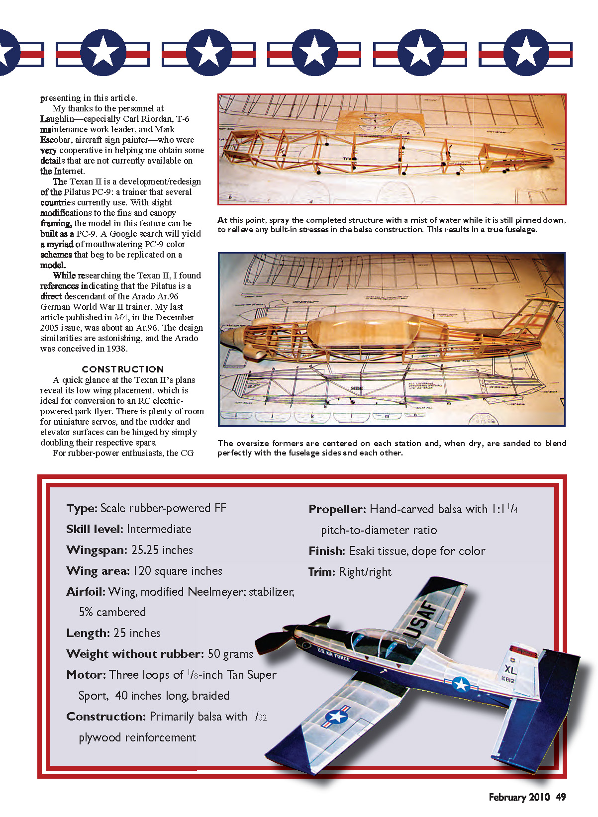
- Type: Scale rubber‑powered free flight
- Skill level: Intermediate
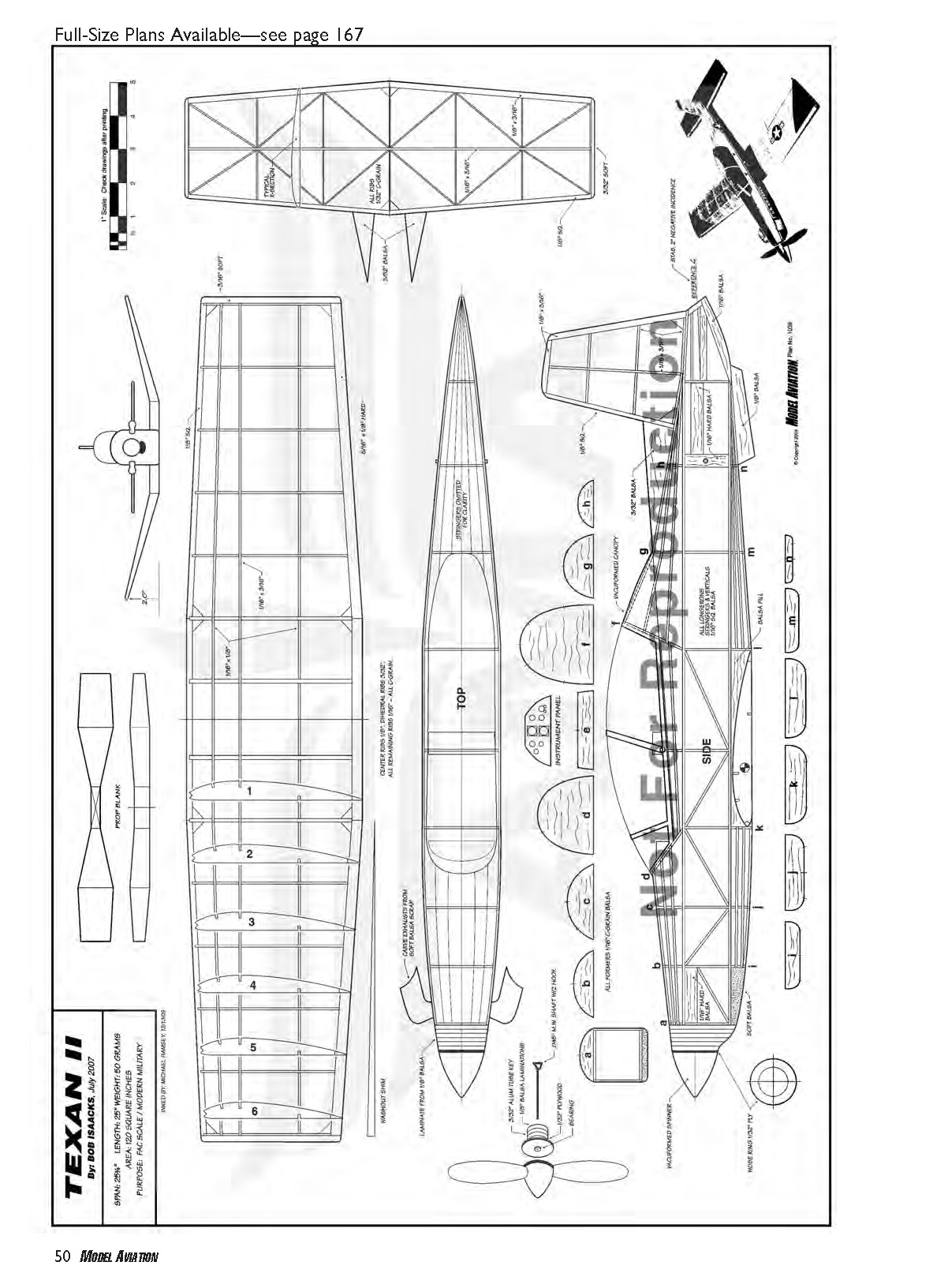
- Wingspan: 25.25 inches
- Wing area: 120 square inches
- Airfoil: Wing, modified Neelmeyer; stabilizer, 5% cambered
- Length: 25 inches
- Weight without rubber: 50 grams
- Motor: Three loops of 1/8‑inch Tan Super Sport, 40 inches long, braided
- Construction: Primarily balsa with 1/32‑inch plywood reinforcement
- Propeller: Hand‑carved balsa with 1‑1/4 pitch‑to‑diameter ratio
- Finish: Esaki tissue, nitrate dope for color
- CG: Sits almost exactly halfway between the model’s rear peg and nose—perfect for a long motor
Construction
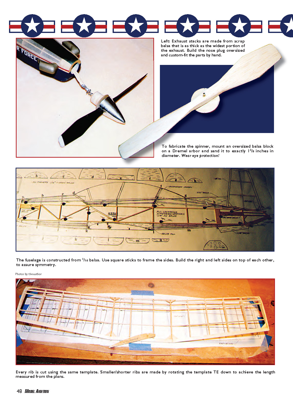
The fuselage build is based on the conventional box/former method. All components are 1/16‑inch balsa except for the nose blocks. Pin and build one fuselage side on top of the other, noting that all verticals on the box are the same length. I made a stop on a miter box and cut all the verticals at one time. The rear‑peg support can be cut at the same time as the 1/16‑inch uprights.
The fuselage longerons are straight except for the rear of the top longeron; notch and “crack” it to match the fuselage/rudder rear line. After the sides are completed and separated, pin them to the top view on the plans and add the crosspieces in the cabin area. Use a square to keep the sides vertical. When the cement is dry on the crosspieces, glue the tail and front crosspieces in place, making sure the nose and tail are square and centered on the plans. Add the remaining crosspieces, front and rear, checking for squareness at each station.
Spray the completed structure with a mist of water while it is still pinned to the plans and allow it to dry. Remove the structure from the board and lightly sand the framework, rounding the top decking and bottom where indicated on the plans. Add the nose blocks and sand them to shape. Sheet the nose with 1/32‑inch plywood and install the firewall.
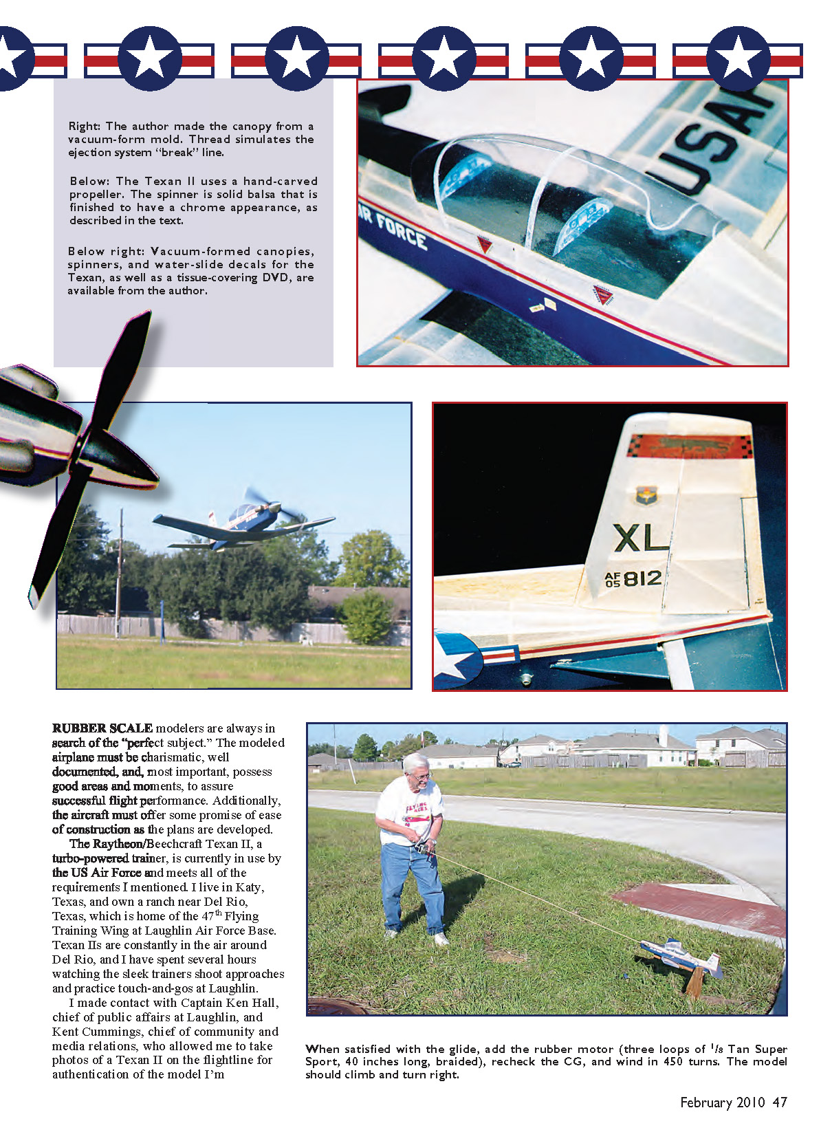
Make the cockpit coaming and bulkheads from the plan patterns. The canopy shown in the photos was vacuum‑formed; thread can be used to simulate the ejection‑system “break” line.
Glass over any joints that need reinforcement, then sand smooth. Cover the fuselage with Esaki tissue and apply nitrate dope for color, following the paint scheme on the plans or your chosen scheme.
Fuselage details and extras
- Copy the formers onto bond paper and use rubber cement to attach the copies to the appropriate thickness of balsa sheet. After cutting the formers from the sheet, peel off the paper copies; slight rubbing removes the rubber cement residue.
- Center the oversize formers on each station; when dry, sand them to blend with the fuselage sides.
- Add the center stringer, making sure it is straight front to rear, then add remaining stringers, alternating sides and measuring for symmetry. Use a small Swiss file to notch the formers for a perfect fit.
- After the bottom stringers are in place and dry, remove the fuselage from the plans and add the top formers.
- Cockpit flooring: extremely light 1/32 balsa, applied cross‑grained to the box.
- Nose block: laminate 1/8 balsa for the nose block and add a bottom chin block. Leave slightly oversize, add a 1/32 plywood nose ring, and sand/blend to profile using plans and photos.
- Drill the initial undersized hole for the nose plug using a router bit and Dremel; finish/size with a sandpaper‑wrapped dowel.
Exhaust stacks: Make from scrap balsa as thick as the widest portion of the exhaust. Copy the top view on bond paper, rubber‑cement to the scrap, and jigsaw to shape. Carve and sand to shape, hollowing with a Dremel cutter. Use a circle template to inscribe a ring on the inner portion of the exhaust where it attaches to the fuselage; carve/sand to that ring for proper profile.
Spinner: Cut a piece of 1/32 plywood slightly larger than 1 3/8 inches. Mount on a Dremel arbor and sand to exactly 1 3/8 inches. Glue an oversized balsa block to the plywood disc (rout a small recess to clear the arbor screw), allow glue to dry, then rough‑shape with an X‑Acto before spinning and final sanding. Wear eye protection.
Nose plug: Make from laminated 1/8 sheet. Spin/sand a plywood disk to 3/4 inch, glue the oversized laminated balsa plug to the disk and spin to size, checking fit to the nose block. Fit a 1 3/8‑inch‑diameter 1/32 plywood disk to the front of the plug and glue it. Drill the nose plug on center with the other end of the plug resting on a 4 1/4° wedge; when rotated correctly, the plug will yield the desired 3° of downthrust and right thrust. Install a brass tubing bushing with an ID matching the propeller‑shaft OD.
Wing
Make a rib template from 1/16 plywood by copying the root rib on bond paper, rubber‑cementing the reproduction to the plywood, jigsawing, and sanding to exact profile. Drive two straight pins through the template so they project 1/16 inch below the bottom surface; use CA to adhere the pins and cut them off above the top surface. These pins hold the template to the balsa when cutting ribs with an X‑Acto knife.
Cut every rib using the same template. Make smaller/shorter ribs by rotating the template TE‑down to achieve the measured length from the plans; the point of rotation is the center of the LE notch.
Pin down the TE along its entire length and add the ribs, ensuring they are square to the building board. Add the LE in the fish‑mouth front of the ribs and the wingtips. When dry, remove the assembly and sight over the top of the ribs to make sure there is a uniform taper from root to tip. Use a long sanding block to remove high spots in the upper camber.
Use a steel straightedge to mark spar locations and notch the ribs with a small Swiss file. Glue the spars in place except for the bottom spar on the outer wing sections. To ensure washout (TE high at the wingtips) is built into the structure, pin the LE down and raise the TE using the wedge shown on the plans. Glue the bottom spar in place.
Sand a bevel on the outer wing‑panel LE, TE, and spars to allow for the 2‑inch dihedral on each panel. Glue the outer panels in place, measuring to assure equal dihedral on both sides. Add dihedral braces and gussets, give the wing a final sanding, and finish.
Tail Feathers
Build the tail surfaces similarly to the wing, with these exceptions:
- Rudder: built with a symmetrical airfoil—shim the LE and TE off the building board before adding the ribs. Airfoil the rudder on both sides.
- Stabilizer: flat‑bottomed, so pin directly to the board; airfoil the top surface only (5% camber).
- Double the spars at the hinge lines for strength and sand to the airfoil contours shown.
- Cut stabilizer strakes and the rudder forward fin, sand the appropriate edges, and the tail surfaces are ready to cover.
Propeller and Spinner
Carve the propeller by hand using the profile shown on the plans. Jigsaw the top "bowtie" profile and drill a 3/32‑inch hole in the center. Jigsaw the side profile. Begin carving the back of the propeller, moving slowly to maintain symmetry. Use a small balsa sanding block with a 5% arc on its upper surface to sand a slight undercamber on the blades. Carve a camber on the top surface by feel to attain equal thickness on both blades.
Spin and sand a 1 3/8‑inch‑diameter 1/32 plywood backplate and enlarge the center hole to 3/32 inch. Install the propeller on the backplate using 3/32‑inch‑OD brass tubing to bush both the backplate and propeller. Install a larger brass‑tube "clutch" over the bushing. Add the hollowed‑out balsa spinner or a vacuum‑formed version after finishing the propeller, backplate, nose plug, shaft, and bearing assembly.
Finishing
The traditional nitrate dope and Esaki tissue method was used to finish the Texan.
- Prepare all surfaces by coating every area that will contact tissue with several coats of nitrate dope, sanding after the first coat. Apply enough dope so the surfaces appear glossy.
- Apply white Esaki tissue wet using 70% alcohol as the wetting agent. Use thinner brushed through the tissue to apply it to the airframe; apply thinner only to the periphery of the surface being covered so the wet tissue can shrink evenly for a superior, wrinkle‑free finish.
- Tissue overlaps require a second coat of dope on the overlapped surface to adhere properly.
- After the tissue is dry and shrunk, brush it with a coat of nitrate dope thinned 50%.
Color and detailing:
- The red stripe on the fuselage is a piece of red Esaki applied with thinner and given a coat of the 50/50 nitrate.
- The blue fuselage bottom, wing underside, top chevrons, and stabilizer were airbrushed using pigment from Dark Blue Floquil model‑train paint mixed into nitrate thinner and added to clear nitrate dope.
- The wing, stabilizer, and rudder leading edges were airbrushed with Old Silver Floquil. Frisket paper was used for masking.
- Trim the canopy and attach it to the finished model with Pacer Formula 560 Canopy Glue.
- The spinner (vacuum‑formed from .030‑inch Vivak) was airbrushed inside with chrome enamel (for model‑car bodies), then coated with flat‑black enamel to give a deep, polished look. Glue the spinner to the propeller backplate with Formula 560.
- Propeller: several coats of clear nitrate mixed with talc to fill the balsa grain, airbrushed with flat‑black enamel, and tips painted flat white.
I have vacuum‑formed canopies, spinners, water‑slide decals, and a tissue‑covering DVD for aeromodellers. I will provide assistance with construction questions via e‑mail—please preface all correspondence with "Texan II" in the subject line.
Flying
My Texan flew "off the board" with little adjustment required.
- Balance and test glide: Remove the propeller and add clay to the nose to get the CG correct. Test‑glide the Texan over high grass by pointing it at a spot about 50 feet ahead and giving it a firm toss toward that spot.
- Trim: Cure diving or stalling with small adjustments to the stabilizer decalage. Cure unwanted turning/spiraling by adding small bits of clay to the wingtip opposite the turn.
- Power flights: When satisfied with the glide, add the rubber motor (three loops of 1/8‑inch Tan Super Sport, 40 inches long, braided). Recheck the CG and wind in 450 turns. When released, the model should climb and turn right; make all adjustments by shimming the thrustline.
- Increasing turns: As the airplane settles in, add turns until you reach approximately 1,750 turns. At that point, have binoculars available and a reliable way to retrieve your model.
Good luck with your Texan II.
Bob Isaacks [email protected]
Transcribed from original scans by AI. Minor OCR errors may remain.

