
Thrust Meter for Electric Motors
George Kyer
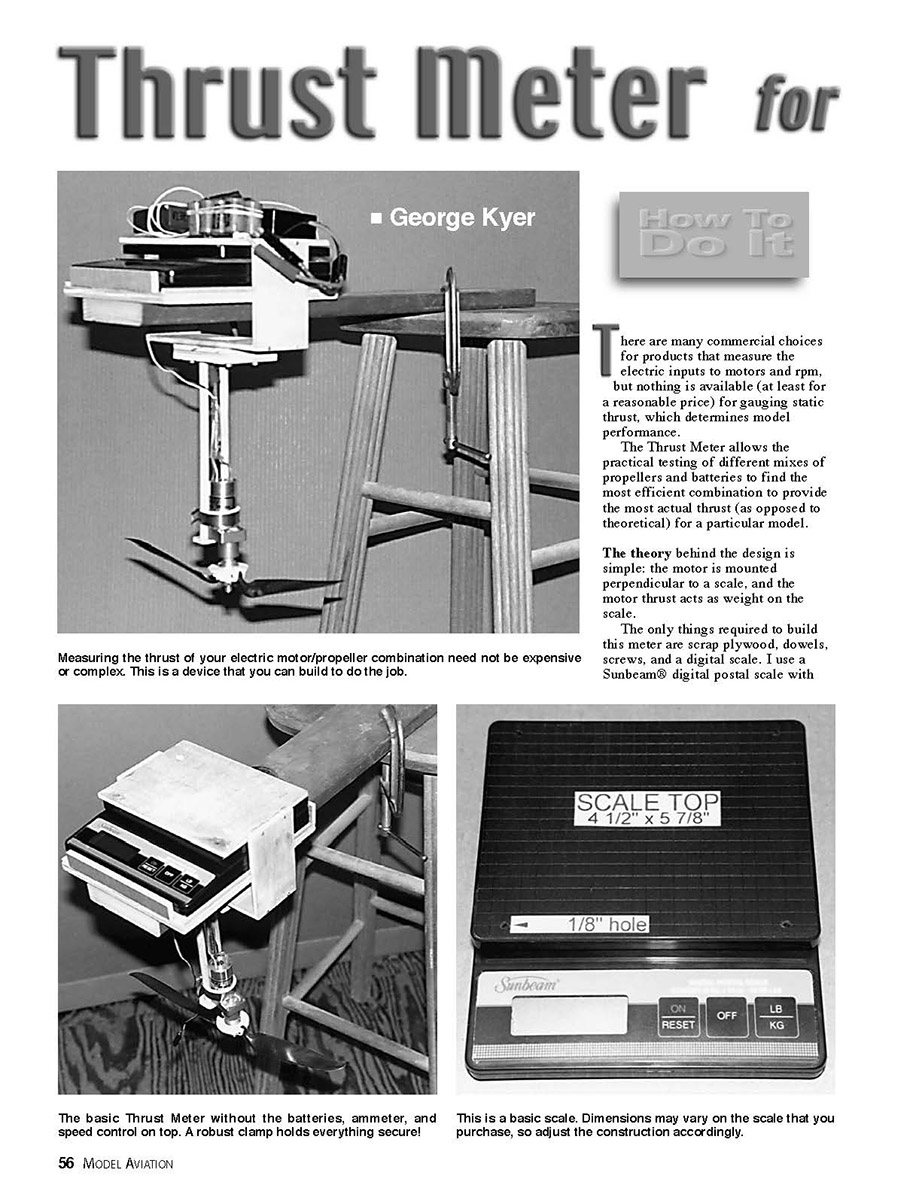
There are many commercial choices for products that measure the electric inputs to motors and rpm, but nothing is available (at least for a reasonable price) for gauging static thrust, which determines model performance.
The Thrust Meter allows the practical testing of different mixes of propellers and batteries to find the most efficient combination to provide the most actual thrust (as opposed to theoretical) for a particular model.
The theory behind the design is simple: the motor is mounted perpendicular to a scale, and the motor thrust acts as weight on the scale.
The only things required to build this meter are scrap plywood, dowels, screws, and a digital scale. I use a Sunbeam® digital postal scale with 10-pound capacity in one-quarter-ounce increments, which I purchased at an Office Depot store for approximately $35. The scale is also handy for weighing models and components when it's not being used in the Thrust Meter.
I recommend using an AstroFlight Whatt Meter (or ammeter) in conjunction with the scale. It is unnecessary for Thrust Meter operation, but it will allow you to monitor battery performance and will alert you to unacceptably high amperage readings for your particular motor. You can also compare actual battery/propeller/motor performance with theoretical data.
The Thrust Meter is easy to use with the following steps:
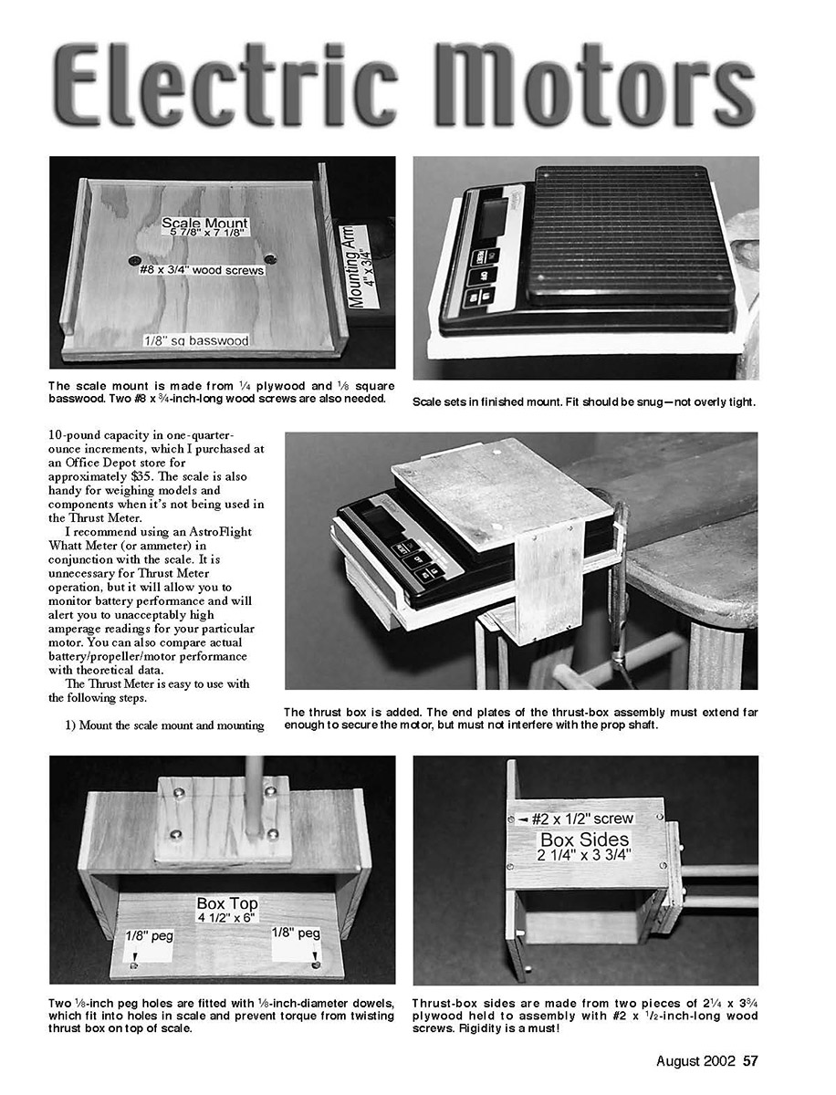
- Mount the scale mount and mounting arm to a firm surface. I use a stool.
- Put the scale in the scale mount.
- Place the thrust box over the scale with the motor mounted. Put the batteries and ammeter (and receiver and speed control if used) on top of the thrust box and scale.
- Don't allow the preceding items or wiring to touch the scale base; that will cause drag and false readings.
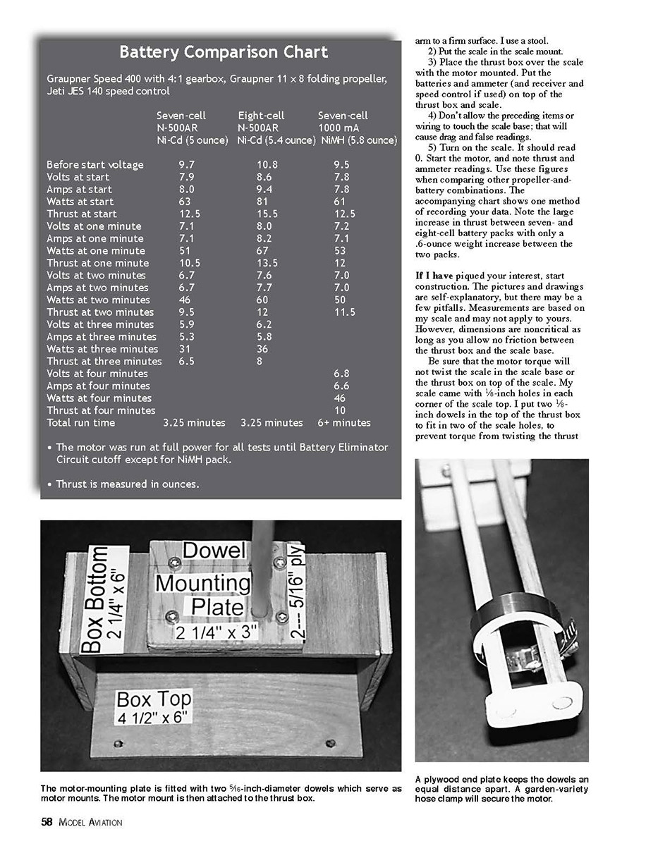
- Turn on the scale. It should read 0. Start the motor, and note the thrust and ammeter readings. Use these figures when comparing other propeller-and-battery combinations. The accompanying chart shows one method of recording your data. Note the large increase in thrust between seven- and eight-cell battery packs with only a 6-ounce weight increase between the two packs.
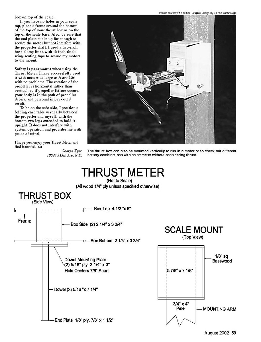
If I have piqued your interest, start construction. The pictures and drawings are self-explanatory, but there may be a few pitfalls. Measurements are based on my scale and may not apply to yours. However, dimensions are noncritical as long as you allow no friction between the thrust box and the scale base.
Be sure that the motor torque will not twist the scale in the scale base or the thrust box on top of the scale. My scale came with 1/8-inch holes in each corner of the scale top. I put two 1/8-inch dowels in the top of the thrust box to fit in two of the scale holes, to prevent torque from twisting the thrust box on top of the scale.
If you have no holes in your scale top, place a frame around the bottom of the top of your thrust box as on the top of the scale base. Also, be sure that the end plate sticks up far enough to secure the motor but not interfere with the propeller shaft. I used a two-inch hose clamp lined with 1/8-inch-thick wing-seating tape to secure my motors to the mount.
Safety is paramount when using the Thrust Meter. I have successfully used it with motors as large as Astro 15s with no problems. The rotation of the propeller is horizontal rather than vertical, so if propeller failure occurs, your body is in the path of propeller debris, and personal injury could result.
To be on the safe side, I position a folding card table vertically between the propeller and myself, with the bottom two legs extended to hold it upright. It does not interfere with system operation and provides me with peace of mind.
I hope you enjoy your Thrust Meter and find it useful.
George Kyer 10824 313th Ave. N.E.
THRUST METER
(Not to Scale) (All wood 1/4" ply unless specified otherwise)
THRUST BOX
(Side View)
Box Top 4 1/2" x 6"
Frame
Box Side (2) 2 1/4" x 3 3/4"
Box Bottom 2 1/4" x 3 3/4"
Dowel Mounting Plate (2) 5/16" ply, 2 1/4" x 3" Hole Centers 7/8" Apart
Dowel (2) 5/16" x 7 1/4"
End Plate 1/8" ply, 7/8" x 1 1/2"
SCALE MOUNT
(Top View)
1/8" sq Basswood
5 7/8" x 7 1/8"
3/4" x 4" Pine MOUNTING ARM
Transcribed from original scans by AI. Minor OCR errors may remain.

