
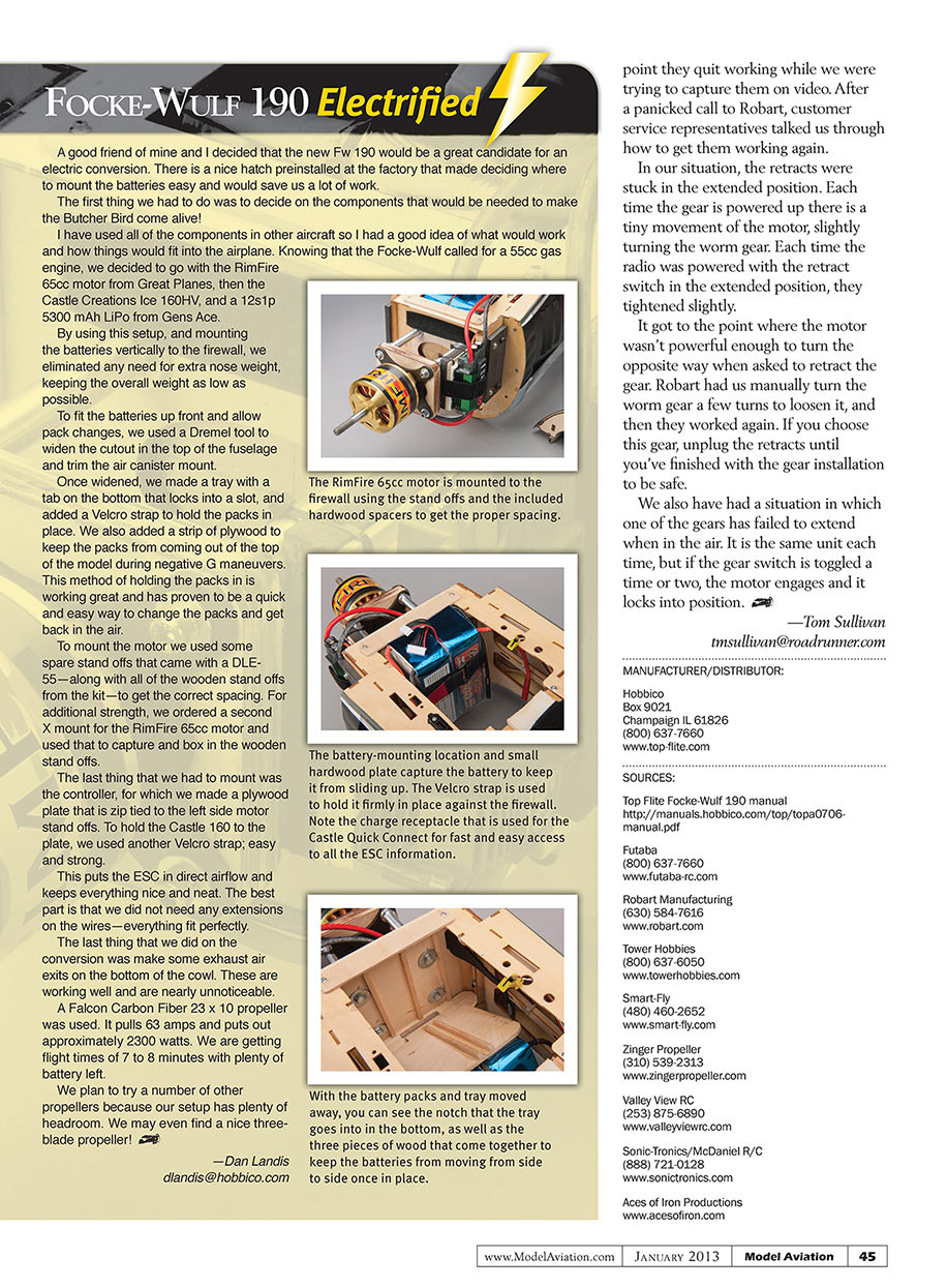
Top Flite Fw 190
Tom Sullivan
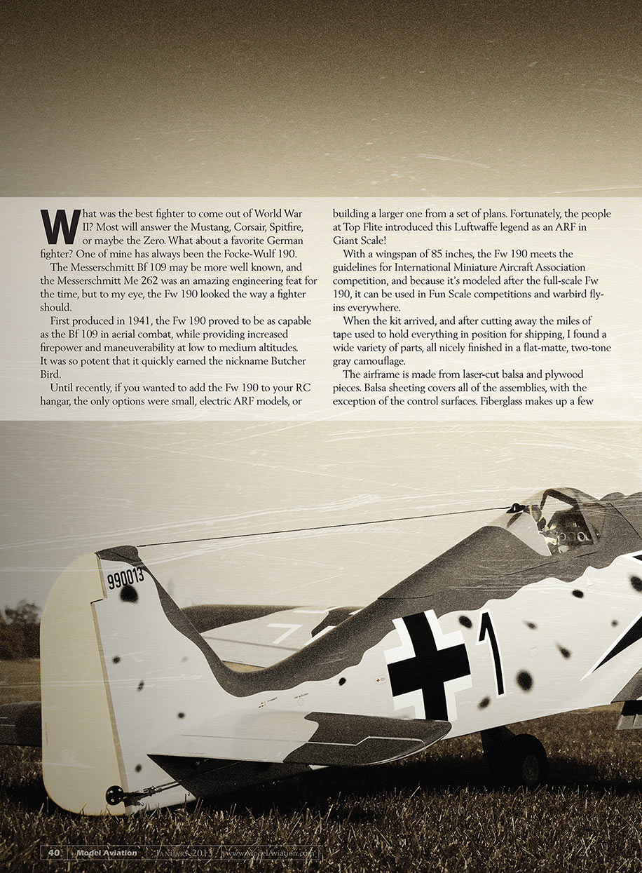
What was the best fighter to come out of World War II? Most will answer the Mustang, Corsair, Spitfire, or maybe the Zero. What about a favorite German fighter? One of mine has always been the Focke-Wulf 190.
The Messerschmitt Bf 109 may be more well known, and the Messerschmitt Me 262 was an amazing engineering feat for the time, but to my eye, the Fw 190 looked the way a fighter should.
First produced in 1941, the Fw 190 proved to be as capable as the Bf 109 in aerial combat, while providing increased firepower and maneuverability at low to medium altitudes. It was so potent that it quickly earned the nickname Butcher Bird.
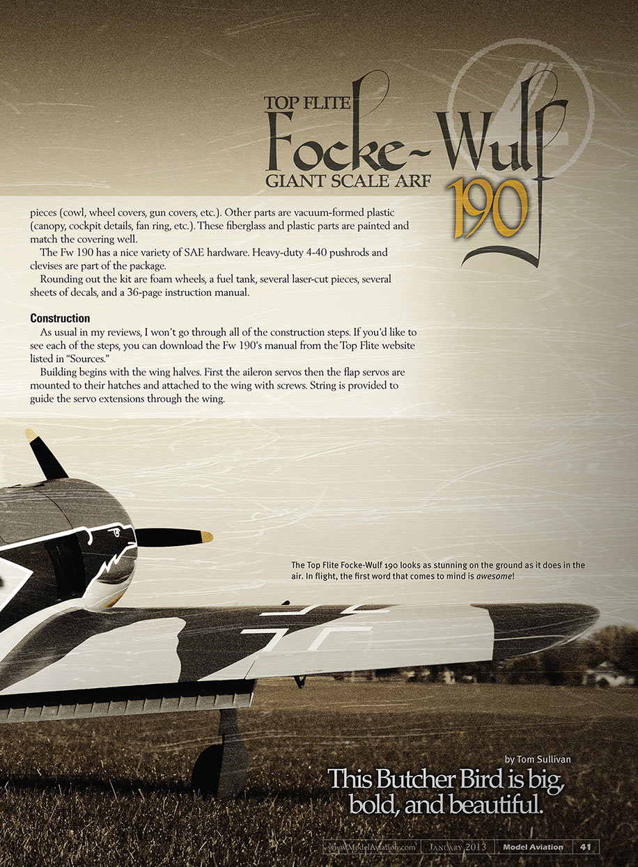
Until recently, if you wanted to add the Fw 190 to your RC hangar, the only options were small, electric ARF models, or building a larger one from a set of plans. Fortunately, the people at Top Flite introduced this Luftwaffe legend as an ARF in Giant Scale!
With a wingspan of 85 inches, the Fw 190 meets the guidelines for International Miniature Aircraft Association competition, and because it's modeled after the full-scale Fw 190, it can be used in Fun Scale competitions and warbird fly-ins everywhere.
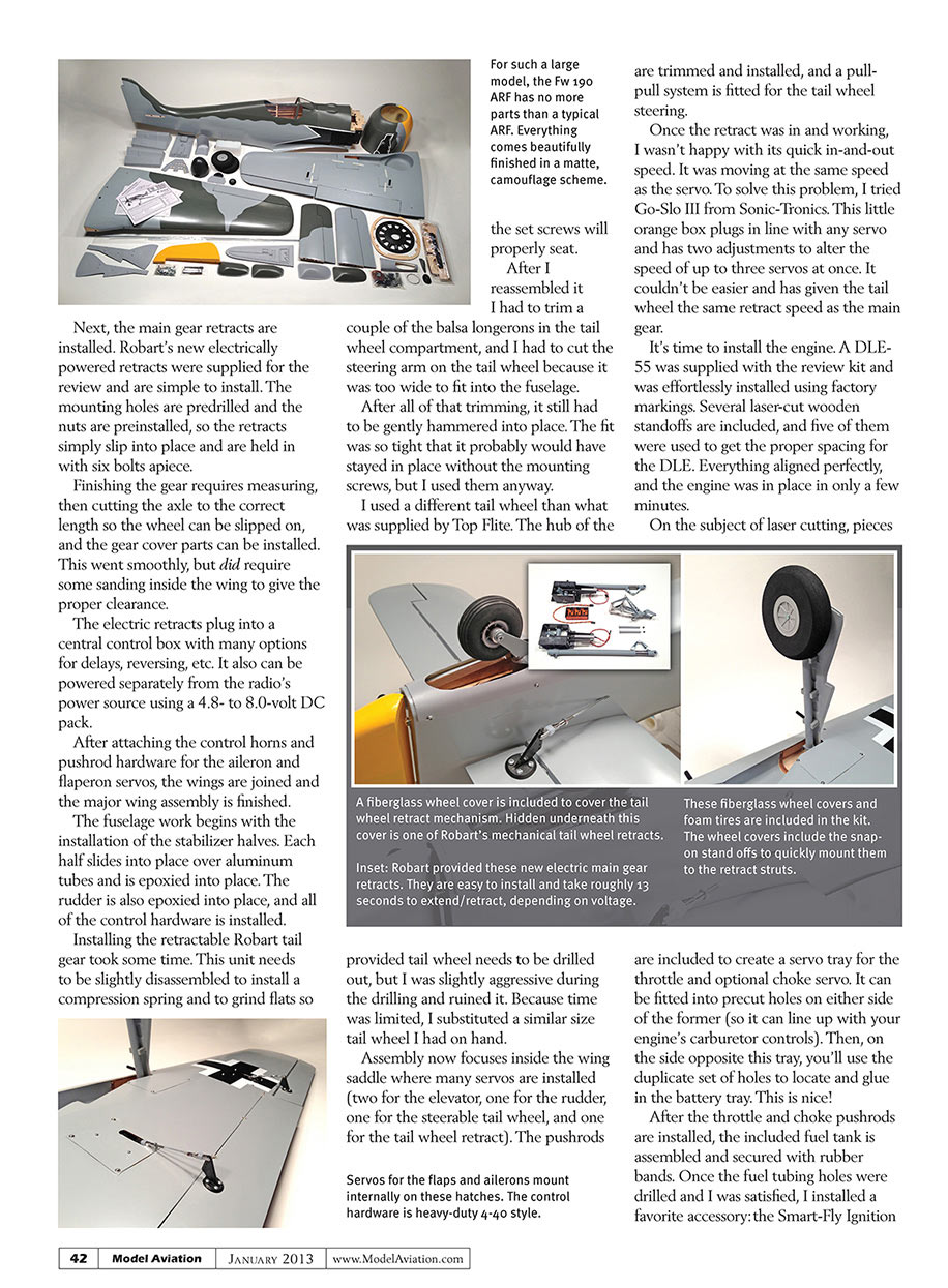
When the kit arrived, and after cutting away the miles of tape used to hold everything in position for shipping, I found a wide variety of parts, all nicely finished in a flat-matte, two-tone gray camouflage.
The airframe is made from laser-cut balsa and plywood pieces. Balsa sheeting covers all of the assemblies, with the exception of the control surfaces. Fiberglass makes up a few pieces (cowl, wheel covers, gun covers, etc.). Other parts are vacuum-formed plastic (canopy, cockpit details, fan ring, etc.). These fiberglass and plastic parts are painted and match the covering well.
The Fw 190 has a nice variety of SAE hardware. Heavy-duty 4-40 pushrods and clevises are part of the package.
Rounding out the kit are foam wheels, a fuel tank, several laser-cut pieces, several sheets of decals, and a 36-page instruction manual.
Construction
As usual in my reviews, I won't go through all of the construction steps. If you'd like to see each of the steps, you can download the Fw 190's manual from the Top Flite website listed in "Sources."
Building begins with the wing halves. First the aileron servos then the flap servos are mounted to their hatches and attached to the wing with screws. String is provided to guide the servo extensions through the wing. Next, the main gear retracts are installed. Robart’s new electrically powered retracts were supplied for the review and are simple to install. The mounting holes are predrilled and the nuts are preinstalled, so the retracts simply slip into place and are held in with six bolts apiece.
Finishing the gear requires measuring, then cutting the axle to the correct length so the wheel can be slipped on, and the gear cover parts can be installed. This went smoothly, but did require some sanding inside the wing to give the proper clearance.
The electric retracts plug into a central control box with many options for delays, reversing, etc. It also can be powered separately from the radio’s power source using a 4.8- to 8.0-volt DC pack.
After attaching the control horns and pushrod hardware for the aileron and flaperon servos, the wings are joined and the major wing assembly is finished.
The fuselage work begins with the installation of the stabilizer halves. Each half slides into place over aluminum tubes and is epoxied into place. The rudder is also epoxied into place, and all of the control hardware is installed.
Installing the retractable Robart tail gear took some time. This unit needs to be slightly disassembled to install a compression spring and to grind flats so the set screws will properly seat.
After I reassembled it I had to trim a couple of the balsa longerons in the tail wheel compartment, and I had to cut the steering arm on the tail wheel because it was too wide to fit into the fuselage.
After all of that trimming, it still had to be gently hammered into place. The fit was so tight that it probably would have stayed in place without the mounting screws, but I used them anyway.
I used a different tail wheel than what was supplied by Top Flite. The hub of the provided tail wheel needs to be drilled out, but I was slightly aggressive during the drilling and ruined it. Because time was limited, I substituted a similar size tail wheel I had on hand.
Assembly now focuses inside the wing saddle where many servos are installed (two for the elevator, one for the rudder, one for the steerable tail wheel, and one for the tail wheel retract). The pushrods are trimmed and installed, and a pull-pull system is fitted for the tail wheel steering.
Once the retract was in and working, I wasn’t happy with its quick in-and-out speed. It was moving at the same speed as the servo. To solve this problem, I tried Go-Slo III from Sonic-Tronics. This little orange box plugs in line with any servo and has two adjustments to alter the speed of up to three servos at once. It couldn’t be easier and has given the tail wheel the same retract speed as the main gear.
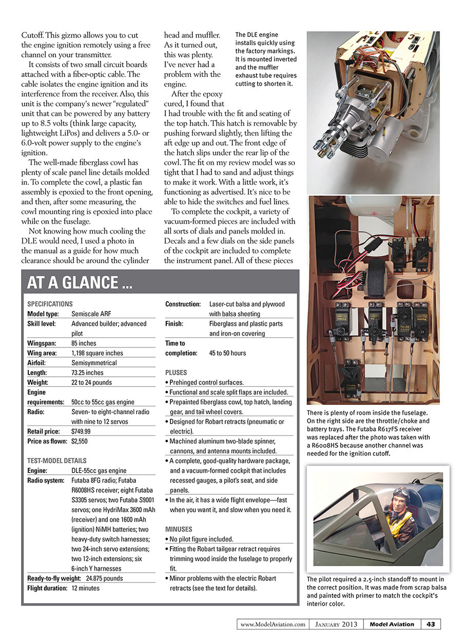
It’s time to install the engine. A DLE-55 was supplied with the review kit and was effortlessly installed using factory markings. Several laser-cut wooden standoffs are included, and five of them were used to get the proper spacing for the DLE. Everything aligned perfectly, and the engine was in place in only a few minutes.
On the subject of laser cutting, pieces are included to create a servo tray for the throttle and optional choke servo. It can be fitted into precut holes on either side of the former (so it can line up with your engine’s carburetor controls). Then, on the side opposite this tray, you’ll use the duplicate set of holes to locate and glue in the battery tray. This is nice!
After the throttle and choke pushrods are installed, the included fuel tank is assembled and secured with rubber bands. Once the fuel tubing holes were drilled and I was satisfied, I installed a favorite accessory: the Smart-Fly Ignition Cutoff. This gizmo allows you to cut the engine ignition remotely using a free channel on your transmitter.
It consists of two small circuit boards attached with a fiber-optic cable. The cable isolates the engine ignition and its interference from the receiver. Also, this unit is the company’s newer “regulated” unit that can be powered by any battery up to 8.5 volts (think large capacity, lightweight LiPos) and delivers a 5.0- or 6.0-volt power supply to the engine’s ignition.
The well-made fiberglass cowl has plenty of scale panel line details molded in. To complete the cowl, a plastic fan assembly is epoxied to the front opening, and then, after some measuring, the cowl mounting ring is epoxied into place while on the fuselage.
Not knowing how much cooling the DLE would need, I used a photo in the manual as a guide for how much clearance should be around the cylinder head and muffler. As it turned out, this was plenty. I’ve never had a problem with the engine.
After the epoxy cured, I found that I had trouble with the fit and seating of the top hatch. This hatch is removable by pushing forward slightly, then lifting the aft edge up and out. The front edge of the hatch slips under the rear lip of the cowl. The fit on my review model was so tight that I had to sand and adjust things to make it work. With a little work, it’s functioning as advertised. It’s nice to be able to hide the switches and fuel lines.
To complete the cockpit, a variety of vacuum-formed pieces are included with all sorts of dials and panels molded in. Decals and a few dials on the side panels of the cockpit are included to complete the instrument panel. All of these pieces
AT A GLANCE ...
SPECIFICATIONS
Model type: Semiscale ARF
Skill level: Advanced builder; advanced pilot
Wingspan: 85 inches
Wing area: 1,198 square inches
Airfoil: Semisymmetrical
Length: 73.25 inches
Weight: 22 to 24 pounds
Engine requirements: 50cc to 55cc gas engine
Radio: Seven- to eight-channel radio with nine to 12 servos
Retail price: $749.99
Price as flown: $2,550
TEST-MODEL DETAILS
Engine: DLE-55cc gas engine
Radio system: Futaba 8FG radio; Futaba R6008HS receiver; eight Futaba S3305 servos; two Futaba S9001 servos; one Hydriimax 3600 mAh (receiver) and one 1600 mAh (ignition) NiMH batteries; two heavy-duty switch harnesses; two 24-inch servo extensions; two 12-inch extensions; six 6-inch Y harnesses
Ready-to-fly weight: 24.875 pounds
Flight duration: 12 minutes
Construction: Laser-cut balsa and plywood with balsa sheeting
Finish: Fiberglass and plastic parts and iron-on covering
Time to completion: 45 to 50 hours
PLUSES
- Prehinged control surfaces.
- Functional and scale split flaps are included.
- Prepainted fiberglass cowl, top hatch, landing gear, and tail wheel covers.
- Designed for Robart retracts (pneumatic or electric).
- Machined aluminum two-blade spinner, cannons, and antenna mounts included.
- A complete, good-quality hardware package, and a vacuum-formed cockpit that includes recessed gauges, a pilot’s seat, and side panels.
- In the air, it has a wide flight envelope—fast when you want it, and slow when you need it.
MINUSES
- No pilot figure included.
- Fitting the Robart tailgear retract requires trimming wood inside the fuselage to properly fit.
- Minor problems with the electric Robart retracts (see the text for details).
require slight trimming and fitting to look and fit properly. I also took the time to paint the cockpit floor and add detail painting to the panels.
No pilot is included, so I purchased the Aces of Iron pilot figure that is referenced in the manual. It’s slightly more expensive than other pilot figures, but I was stunned by the detail and by its light weight.
Aces of Iron has an online painting guide that I used, and when finished, that pilot figure looked great. It required a 2-1/2-inch spacer to bring it to the correct height.
Because all of the cockpit pieces are attached using CA glue, allow everything to dry and cure before gluing the canopy in place. That prevents the windshield from fogging.
Scale details complete the Fw 190. The included aluminum tubes simulate the guns in the cowl, as well as the cannons in the wings. Other vacuum-formed pieces make up the two antenna mounts between the canopy and the vertical fin.
Then there are the many decals. They’re easy to install using the guides in the manual, but the Iron Crosses on top of the wings took some extra work to get into place because they’re only made up of four separate “L” shapes. All of the decals are die-cut, so that’s another nice touch.
With all the assembly and double-checking the radio setup finished, it was time to check the CG. The Fw 190 weighed in at 22-1/2 pounds, including the spinner and three-blade XOAR propeller. However, the CG was far aft, making the Fw 190 tail-heavy.
I double-checked the balance point to be sure, but found that I had to add 2.375 pounds of nose weight, so I went to work. I epoxied approximately 1-1/2 pounds of buckshot around the fan ring of the cowl. I also added weight to the underside of the firewall box. With the additional balance weight, the model came in at 24-7/8 pounds ready to fly.
Flying
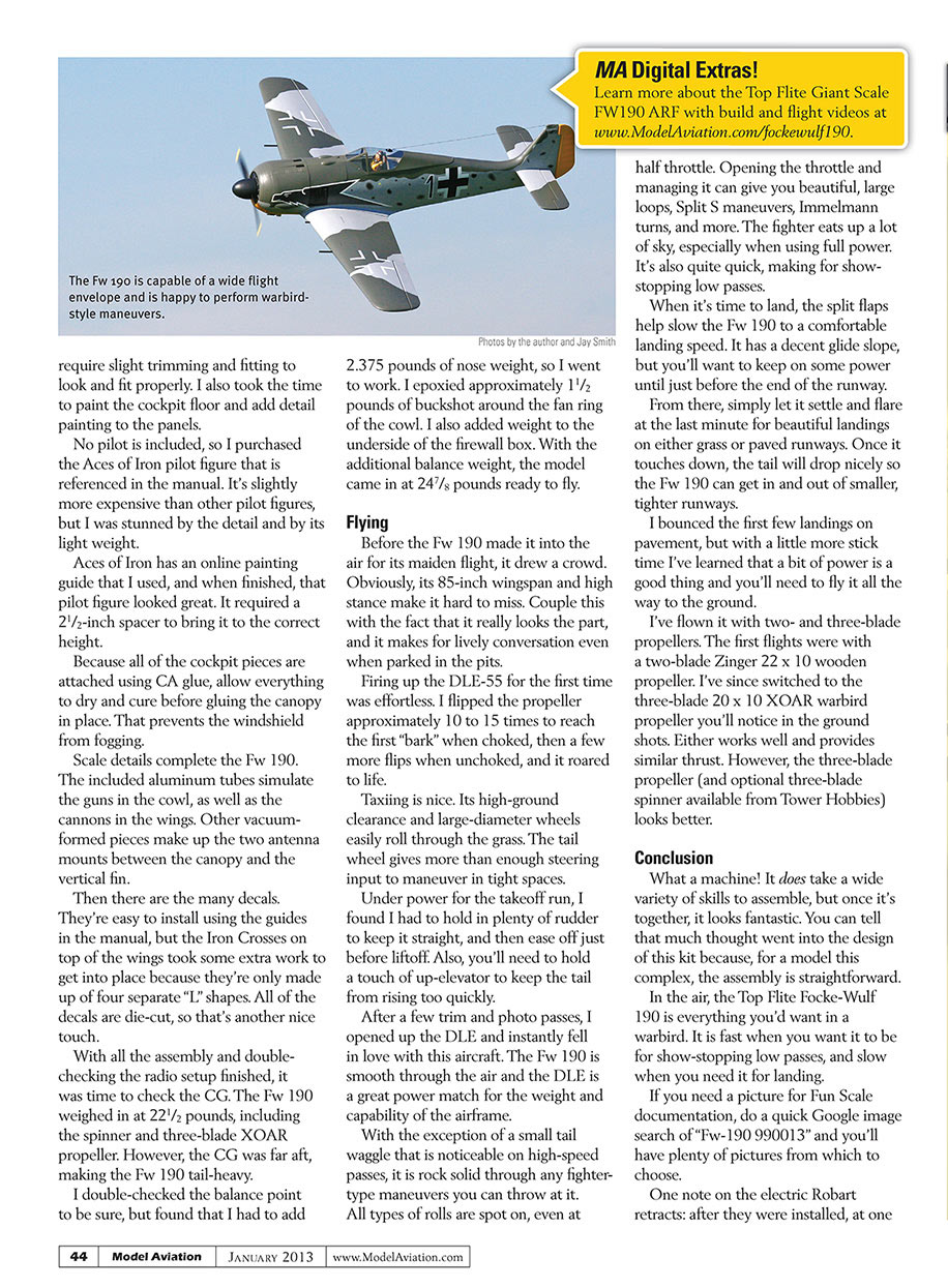
Before the Fw 190 made it into the air for its maiden flight, it drew a crowd. Obviously, its 85-inch wingspan and high stance make it hard to miss. Couple this with the fact that it really looks the part, and it makes for lively conversation even when parked in the pits.
Firing up the DLE-55 for the first time was effortless. I flipped the propeller approximately 10 to 15 times to reach the first “bark” when choked, then a few more flips when unchoked, and it roared to life.
Taxiing is nice. Its high-ground clearance and large-diameter wheels easily roll through the grass. The tail wheel gives more than enough steering input to maneuver in tight spaces.
Under power for the takeoff run, I found I had to hold in plenty of rudder to keep it straight, and then ease off just before liftoff. Also, you’ll need to hold a touch of up-elevator to keep the tail from rising too quickly.
After a few trim and photo passes, I opened up the DLE and instantly fell in love with this aircraft. The Fw 190 is smooth through the air and the DLE is a great power match for the weight and capability of the airframe.
With the exception of a small tail waggle that is noticeable on high-speed passes, it is rock solid through any fighter-type maneuvers you can throw at it. All types of rolls are spot on, even at half throttle. Opening the throttle and managing it can give you beautiful, large loops, Split S maneuvers, Immelmann turns, and more. The fighter eats up a lot of sky, especially when using full power. It’s also quite quick, making for show-stopping low passes.
When it’s time to land, the split flaps help slow the Fw 190 to a comfortable landing speed. It has a decent glide slope, but you’ll want to keep on some power until just before the end of the runway.
From there, simply let it settle and flare at the last minute for beautiful landings on either grass or paved runways. Once it touches down, the tail will drop nicely so the Fw 190 can get in and out of smaller, tighter runways.
I bounced the first few landings on pavement, but with a little more stick time I’ve learned that a bit of power is a good thing and you’ll need to fly it all the way to the ground.
I’ve flown it with two- and three-blade propellers. The first flights were with a two-blade Zinger 22 x 10 wooden propeller. I’ve since switched to the three-blade 20 x 10 XOAR warbird propeller you’ll notice in the ground shots. Either works well and provides similar thrust. However, the three-blade propeller (and optional three-blade spinner available from Tower Hobbies) looks better.
Conclusion
What a machine! It does take a wide variety of skills to assemble, but once it’s together, it looks fantastic. You can tell that much thought went into the design of this kit because, for a model this complex, the assembly is straightforward.
In the air, the Top Flite Focke-Wulf 190 is everything you’d want in a warbird. It is fast when you want it to be for show-stopping low passes, and slow when you need it for landing.
If you need a picture for Fun Scale documentation, do a quick Google image search of “Fw-190 990013” and you’ll have plenty of pictures from which to choose.
One note on the electric Robart retracts: after they were installed, at one point they quit working while we were trying to capture them on video. After a panicked call to Robart, customer service representatives talked us through how to get them working again.
In our situation, the retracts were stuck in the extended position. Each time the gear is powered up there is a tiny movement of the motor, slightly turning the worm gear. Each time the radio was powered with the retract switch in the extended position, they tightened slightly.
It got to the point where the motor wasn't powerful enough to turn the opposite way when asked to retract the gear. Robart had us manually turn the worm gear a few turns to loosen it, and then they worked again. If you choose this gear, unplug the retracts until you've finished with the gear installation to be safe.
We also have had a situation in which one of the gears has failed to extend when in the air. It is the same unit each time, but if the gear switch is toggled a time or two, the motor engages and it locks into position.
—Tom Sullivan
MANUFACTURER/DISTRIBUTOR:
Hobbico Box 9021 Champaign IL 61826 (800) 637-7660 www.top-flite.com
SOURCES:
Top Flite Focke-Wulf 190 manual http://manuals.hobbico.com/top/topa0706-manual.pdf
Futaba (800) 637-7660 www.futaba-rc.com
Robart Manufacturing (630) 584-7616 www.robart.com
Tower Hobbies (800) 637-6050 www.towerhobbies.com
Smart-Fly (480) 460-2652 www.smart-fly.com
Zinger Propeller (310) 539-2313 www.zingerpropeller.com
Valley View RC (253) 875-6090 www.valleyviewrc.com
SonicTronics/McDaniel R/C (888) 721-0128 www.sonictronics.com
Aces of Iron Productions www.acesofiron.com
Transcribed from original scans by AI. Minor OCR errors may remain.

