
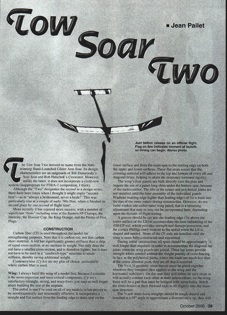
Tow Soar Two
- Jean Pailet
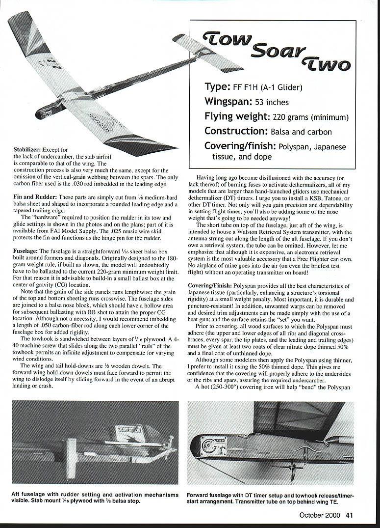
The Tow Soar Two derived its name from the Nats-winning hand-launched glider Arm Soar. Its design characteristics are an outgrowth of Bill Dunwoody's Soar Sam and Bob Hatschek's Circulator. However, unlike the latter, it does not incorporate a circle-tow system (appropriate for F1H/A/1 competition), I think.
Although the "Two" designates the second in a design series, there have been times when I thought it might imply "second-best" — as I'm always a bridesmaid, never a bride! This was particularly true at a couple of early-'90s Nats, when it finished in second place by one second of flight time.
More recently it has enjoyed more success, with a number of significant "firsts" including wins at the Eastern FF Champs, the Intercity, the Hoosier Cup, the King Orange, and the Fiesta of Five Flags.
Construction
Carbon fiber (CF) is used throughout the model for strengthening purposes. Note that it is carbon rod, not thin carbon sheet material. A rod has significantly greater stiffness than a strip of equal cross-section, at no increase in weight. Not only does the rod have a smaller cross-section, and is therefore lighter, but it does not have to be used as a "sandwich-type" structure to attain stiffness, thereby saving additional weight.
Cyanoacrylates (CAs) are my glue of choice, particularly where carbon fiber is used.
Wing
I always build the wing of a model first, because I consider it the most important and most-critical component. If it isn't satisfactory (straight, strong, and warp-free), you may as well forget about building the rest of the airplane.
The airfoil is one I've used on all of my models; it has proven to be aerodynamically and structurally effective. It incorporates a straight and flat surface from the leading edge to the main spar on the lower surface and from the main spar to the trailing edge on both the upper and lower surfaces. These flat areas assure that the covering material will adhere to the top and bottom of every rib and diagonal brace, helping to attain the necessary torsional rigidity.
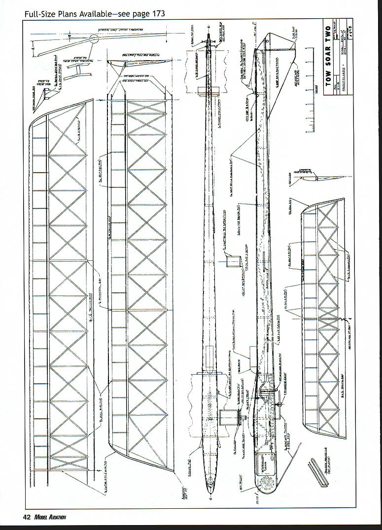
The wing's four panels are built directly over the plan and require the use of a panel-long shim under the bottom spar because of the undercamber. The ribs at the center and polyhedral joints are not installed until the later assembly of the individual panels. A washout (trailing edge higher than leading edge) of 1/2° is built into the tips of the outer panels during construction. However, do not build wash into the inner wing panel; that is a trimming and adjustment that may or may not be incorporated later, depending upon the results of flight testing.
A groove should be cut into the leading edge (1/32 inch above the lower surface of the LE) to accommodate the later embedding of the .032 CF rod, often providing strength and damage protection, and forming the correct entry contour to the airfoil when the LE is shaped and sanded. None of the CF rods are installed until the wing is more fully constructed and assembled.
During initial construction, all spars should be approximately 3/32 inch longer than required in order to accommodate the diagonal lap joints when the wing panels are joined. These lap joints provide strength where needed without the weight penalty of extra bracing. In fact, at the polyhedral joints, where the loads are much less than at the center dihedral joint, less reinforcement is required.
The 1/16 x 3/32 geodetic cross-braces must be glued together wherever they intersect (this applies to the wing and the horizontal stabilizer). On the stubs they will either be very close or will actually contact each other at their intersections; on the wing there will be a gap that must be bridged with scrap balsa. Note the cross-braces at their forward ends are fitted to seat slightly into the main spar structure.
The 1/8-inch soft sheet balsa wingtips should be rough-shaped and installed at a 45° angle to approximate a Hoerner-type tip; they will be finish-shaped and sanded to blend into the outer panel contours later. The top main spar is glued to the tips to support them.
After framing out the four wing panels separately, they are assembled into a one-piece structure. I suggest mating the tip panels to their respective center panels before joining the two center panels. Mating the wing halves at the center dihedral joint is accomplished similarly with spar lap joints and the insertion of the 1/8 center rib.
Now you are ready to install the all-important .030 carbon-fiber rods.
Note that the leading edge and main-panel rods are one continuous piece from polyhedral joint to polyhedral joint. Since they are therefore "curved" through the shallow dihedral angle, it is important to adequately support the wing panels to prevent the rods from achieving their natural tendency to straighten out before the assembly is completed.
The main spar rods must be installed flush with the outer (upper and lower, respectively) surfaces of the 1/16 x 1/8 spruce spars, thereby leaving 1/32 inch of the wood surfaces exposed for subsequent attachment of the shear webs. These 1/32-inch sheet balsa shear webs are now installed between the ribs and between the .030 CF rods and against the wood spars.
A straight four-inch length of .050 CF rod is glued against the rear surface of the LE and a two-inch piece is similarly glued against the front surface of the TE. A straight 10-inch length of .050 CF rod is glued against the front face of the shear webbing. Installation of these straight rods (which substitute for the more conventional plywood gussets) will require carefully notching and/or drilling holes into the various center area ribs through which they must pass.
It is extremely important that the ends of all rods be tapered to a fine point, with the taper extending for at least 1/2 inch. It is also critical that these rods be of different lengths to avoid a stress concentration at any particular spanwise location.
Complete the outer wing panels by installing the 1/32-inch vertical-grain shear webs from polyhedral joints to tips, and by inserting the .030 CF rod into the leading edges. Note that no CF rods are required along the outer panel spars. Finish-shape the soft-balsa wingtips to conform to the wing airfoil.
Stabilizer
Except for the lack of undercamber, the stab airfoil is comparable to that of the wing. The construction process is also very much the same, except for the omission of the vertical-grain webbing between the spars. The only carbon fiber used is the .030 rod embedded in the leading edge.
Fin and Rudder
These parts are simply cut from 1/4-inch medium-hard balsa sheet and shaped to incorporate a rounded leading edge and a tapered trailing edge.
The hardware required to position the rudder in its tow and glide settings is shown in the photos and on the plans; part of it is available from FAI Model Supply. The .025 music-wire skid protects the fin and functions as the hinge pin for the rudder.
Fuselage
The fuselage is a straightforward 1/4-inch sheet balsa box built around formers and diagonals. Originally designed to the 180-gram weight rule, if built as shown the model will undoubtedly have to be ballasted to the current 220-gram minimum weight limit. For that reason it is advisable to build in a small ballast box at the center of gravity (CG) location.
Note that the grain of the side panels runs lengthwise; the grain of the top and bottom sheeting runs crosswise. The fuselage sides are joined to a balsa nose block, which should have a hollow area for subsequent ballasting with BB shot to attain the proper CG location. Although not a necessity, I would recommend embedding a length of .050 carbon-fiber rod along each lower corner of the fuselage box for added rigidity.
The towhook is sandwiched between layers of 1/8-inch plywood. A 4-40 machine screw that slides along the two parallel "rails" of the towhook permits an infinite adjustment to compensate for varying wind conditions.
The wing and tail hold-downs are 1/2-inch wooden dowels. The forward wing hold-down dowels must face forward to permit the wing to dislodge itself by sliding forward in the event of an abrupt landing or crash.
Having long ago become disillusioned with the accuracy (or lack thereof) of burning fuses to activate dethermalizers, all of my models that are larger than hand-launched gliders use mechanical dethermalizer (DT) timers. I urge you to install a KSB, Tatone, or other DT timer. Not only will you gain precision and dependability in setting flight times, you'll also be adding some of the nose weight that's going to be needed anyway!
The short tube on top of the fuselage, just aft of the wing, is intended to house a Walston Retrieval System transmitter, with its antenna strung out along the length of the aft fuselage. If you don't own a retrieval system, the tube can be omitted. However, let me emphasize that although it is expensive, an electronic retrieval system is the most valuable accessory that a FliteRacer can own. No airplane of mine goes into the air (even on the briefest test flight) without an operating transmitter on board!
Covering/Finish
Polyspan provides all the best characteristics of Japanese tissue (particularly, enhancing a structure's torsional rigidity) at a small weight penalty. Most important, it is durable and puncture-resistant. In addition, unwanted warps can be removed and desired trim adjustments can be made simply with the use of a heat gun; and the surface retains the "set" you want.
Prior to covering, all wood surfaces to which the Polyspan must adhere (the upper and lower edges of all ribs and diagonal cross-braces, every spar, the tip plates, and the leading and trailing edges) must be given at least two coats of clear nitrate dope thinned 50% and a final coat of unthinned dope.
Although some modelers then apply the Polyspan using thinner, I prefer to install it using the 50% thinned dope. This gives me confidence that the covering will properly adhere to the undersides of the ribs and spars, assuring the required undercamber.
A hot (250–300°F) covering iron will help "bend" the Polyspan.
Keys
When setting up the alignment of the wing and tail, it is critical that they be at right angles to the fuselage centerline. Once you have established their correct positions, it is just as critical to assure that they align similarly every time they are mounted.
I use 1/16-inch diameter dowels, split lengthwise and glued to the wing and stab undersurfaces, to serve as alignment "keys" against the fuselage sides and against the stab mount. This guarantees their correct positioning every time they are installed.
Flight Testing
My models balance at 61% of the wing chord (2-3/4 inches aft of the LE) and I suggest you use that as a starting point for ballasting your model. Rig the model's rudder and DT line as shown on the plans and photos.
A release pin attached to the towline ring actuates the dethermalizer timer and rudder glide positioning in actual flights. You will have to insert a dummy pin to lock the DT timer and rudder to permit initial trimming during the first hand-launched glide tests. These are aimed at achieving a "straight ahead" glide path for the tow-mode portion of an actual flight, and is attained solely with rudder adjustments.
You should simultaneously adjust for a flat no-stall/no-dive glide path by shimming the leading or trailing edge of the stabilizer as required. Ballasting the nose or tail to shift the CG fore or aft can also help during this stage of trimming.
To trim for the glide mode, keep the timer locked with the dummy release pin but release the rudder line. For no reason other than to be consistent with my power models, I trim my Tow Soar Two for a right-hand glide circle. Whether you decide on right or left glide circles, only repetitive hand-glides and rudder adjustments will yield the desired flat turn.
Ideally, the model should be just on the edge of stalling during the glide-mode portion of an actual flight, to which you can now proceed.
During the tow, wind is both your friend and your foe. Too much, and you risk damaging the model; too little, and you may not be able to turn fast enough or far enough to maintain airspeed and gain altitude.
Assuming a moderate (5 to 10 mph) breeze, begin your tow tests with the towhook screw set slightly (1/2 inch) forward of the CG, and the DT timer set for approximately 30 seconds.
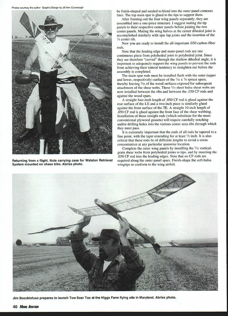
After rigging the model with the DT and rudder-release pin and towline ring in place, have your helper/timer hold the model at a 45° angle facing directly into the wind. He or she should take a step or two with you as you begin to run, but the model should not be thrown; it must simply be released. In a strong wind you may find that you actually have to run toward the model rather than away from it, to avoid imposing damaging excessive loads on it.
Move the towhook screw forward for windy conditions and aft for calmer weather (1/2 to 1/4 inch either way should be enough to make a noticeable difference).
The model should tow straight ahead, without veering appreciably to either side. When released (you have to abruptly slack off on the line) it should settle into a flat glide circle. These two desired flight paths will only be achieved through repetitive testing and trimming.
One other flight adjustment you may be able to experiment with is the use of one or more turbulator strips along the wing leading edge. On my models I use one full-span length of 1/32-inch Chart-Pak® tape 1/2–5/8 inch aft of the leading edge. I think this improves the glide, but like so many facets of our hobby, there is no way to measure it objectively, so it's just a subjective judgment on my part.
If you want to get really adventurous, you might even try a turbulator on the stab. However, be aware that any turbulator use will probably necessitate retrimming the glide.
I want to acknowledge the help rendered through the years by all those guys and gals who have patiently waited with me for the wind and lift to be "just right" before launching my towline gliders. I couldn't have done it without you! Your laughter as I desperately tried to run fast enough to get the models airborne, however, was not as fully appreciated.
Readers who choose to build a Tow Soar Two, or who simply have a question or comment about any of the above, are encouraged to contact me.
Jean G. Paillet 30 Emerson Rd. Brookville, NY 11545
Sources:
- Carbon-fiber rods, etc.:
- Aerospace Composite Products
- 14210 Dolittle Dr.
- San Leandro, CA 94577
- Timers, Polyspan, and hardware:
- FAI Model Supply
- Box 366
- Sayre, PA 18840
- Retrieval Systems:
- Jim Walston
- 725 Cooper Lake Rd., S.E.
- Smyrna, GA 30082
Transcribed from original scans by AI. Minor OCR errors may remain.

