
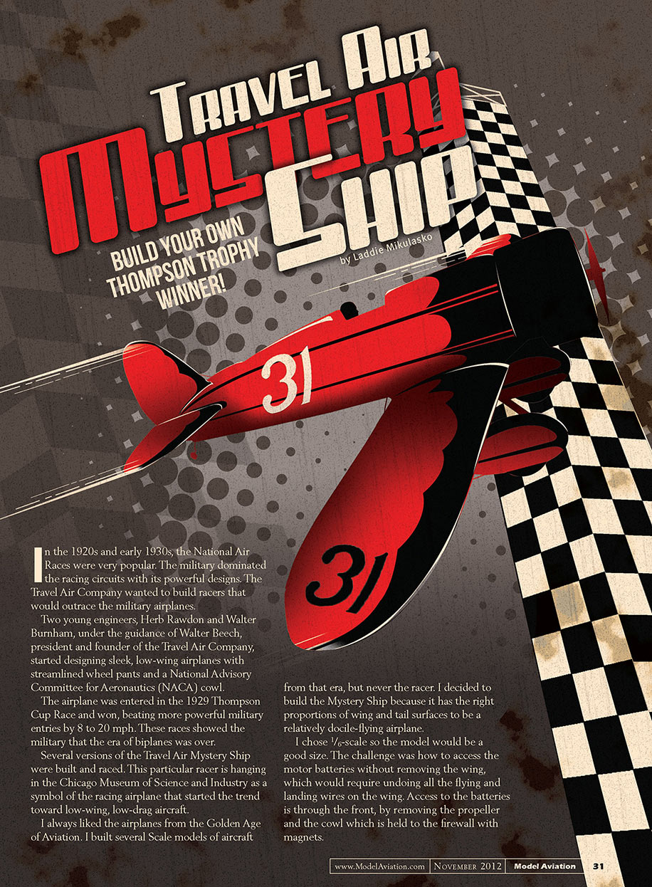
Travel Air Mystery Ship
BUILD YOUR OWN THOMPSON TROPHY WINNER!
by Laddie Mikulasko
In the 1920s and early 1930s, the National Air Races were very popular. The military dominated the racing circuits with its powerful designs. The Travel Air Company wanted to build racers that would outrace the military airplanes.
Two young engineers, Herb Rawdon and Walter Burnham, under the guidance of Walter Beech, president and founder of the Travel Air Company, started designing sleek, low-wing airplanes with streamlined wheel pants and a National Advisory Committee for Aeronautics (NACA) cowl.
The airplane was entered in the 1929 Thompson Cup Race and won, beating more powerful military entries by 8 to 20 mph. These races showed the military that the era of biplanes was over.
Several versions of the Travel Air Mystery Ship were built and raced. This particular racer is hanging in the Chicago Museum of Science and Industry as a symbol of the racing airplane that started the trend toward low-wing, low-drag aircraft.
I always liked the airplanes from the Golden Age of Aviation. I built several scale models of aircraft from that era, but never the racer. I decided to build the Mystery Ship because it has the right proportions of wing and tail surfaces to be a relatively docile-flying airplane.
I chose 1/6-scale so the model would be a good size. The challenge was how to access the motor batteries without removing the wing, which would require undoing all the flying and landing wires on the wing. Access to the batteries is through the front, by removing the propeller and the cowl which is held to the firewall with magnets.
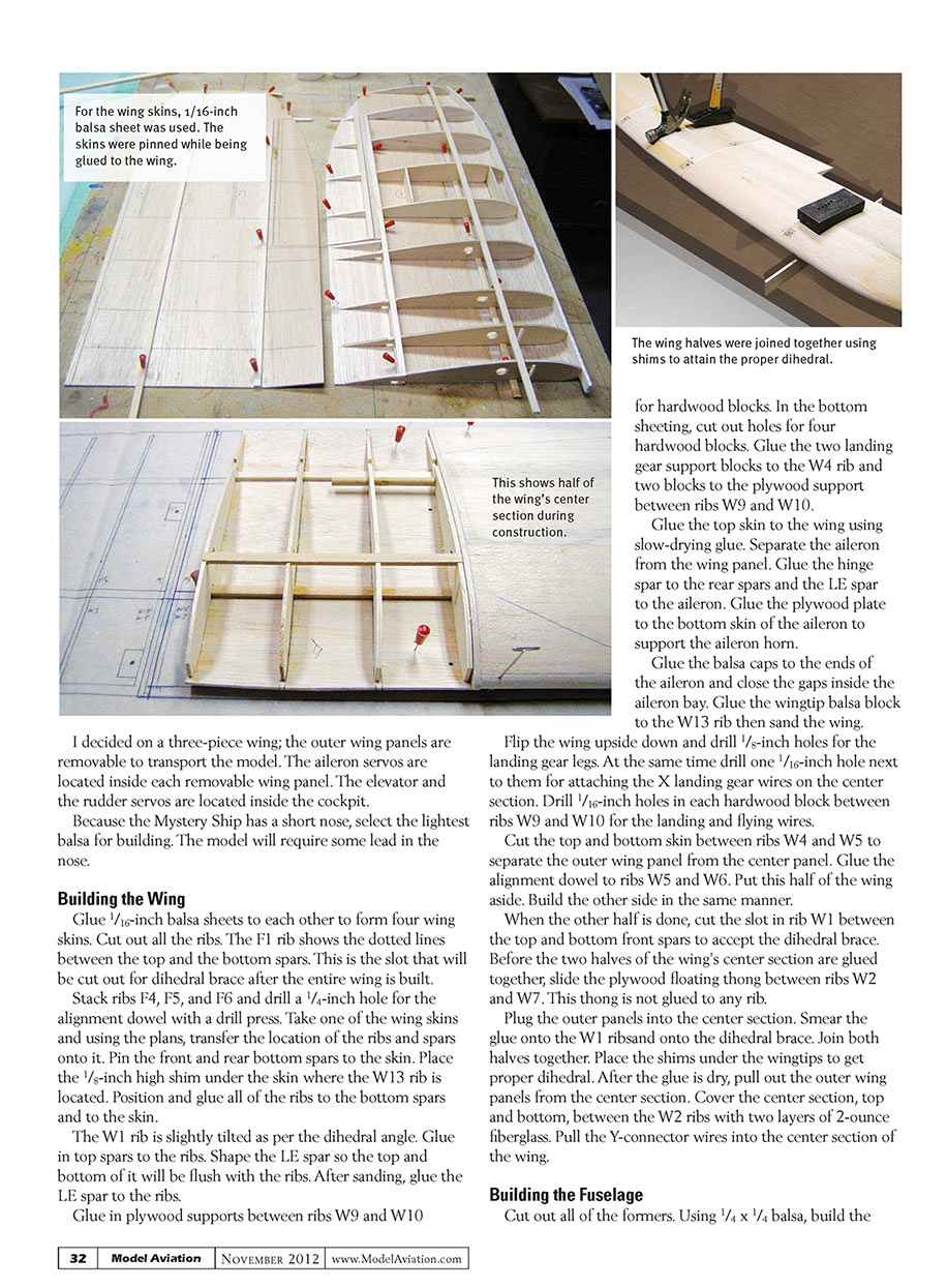
For the wing skins, 1/16-inch balsa sheet was used. The skins were pinned while being glued to the wing. The wing halves were joined together using shims to attain the proper dihedral. This shows half of the wing’s center section during construction.
I decided on a three-piece wing; the outer wing panels are removable to transport the model. The aileron servos are located inside each removable wing panel. The elevator and the rudder servos are located inside the cockpit.
Because the Mystery Ship has a short nose, select the lightest balsa for building. The model will require some lead in the nose.
Building the Wing
Glue 1/16-inch balsa sheets to each other to form four wing skins. Cut out all the ribs. The F1 rib shows the dotted lines between the top and the bottom spars. This is the slot that will be cut out for the dihedral brace after the entire wing is built.
Stack ribs F4, F5, and F6 and drill a 1/4-inch hole for the alignment dowel with a drill press.
Take one of the wing skins and, using the plans, transfer the location of the ribs and spars onto it. Pin the front and rear bottom spars to the skin. Place the 1/8-inch high shim under the skin where the W13 rib is located. Position and glue all of the ribs to the bottom spars and to the skin. The W1 rib is slightly tilted as per the dihedral angle. Glue in top spars to the ribs. Shape the LE spar so the top and bottom of it will be flush with the ribs. After sanding, glue the LE spar to the ribs.
Glue in plywood supports between ribs W9 and W10 for hardwood blocks. In the bottom sheeting, cut out holes for four hardwood blocks. Glue the two landing gear support blocks to the W4 rib and two blocks to the plywood support between ribs W9 and W10. Glue the top skin to the wing using slow-drying glue.
Separate the aileron from the wing panel. Glue the hinge spar to the rear spars and the LE spar to the aileron. Glue the plywood plate to the bottom skin of the aileron to support the aileron horn. Glue the balsa caps to the ends of the aileron and close the gaps inside the aileron bay. Glue the wingtip balsa block to the W13 rib then sand the wing.
Flip the wing upside down and drill 1/8-inch holes for the landing gear legs. At the same time drill one 1/16-inch hole next to them for attaching the X landing gear wires on the center section. Drill 1/16-inch holes in each hardwood block between ribs W9 and W10 for the landing and flying wires.
Cut the top and bottom skin between ribs W4 and W5 to separate the outer wing panel from the center panel. Glue the alignment dowel to ribs W5 and W6. Put this half of the wing aside. Build the other side in the same manner.
When the other half is done, cut the slot in rib W1 between the top and bottom front spars to accept the dihedral brace. Before the two halves of the wing's center section are glued together, slide the plywood floating tongue between ribs W2 and W7. This tongue is not glued to any rib.
Plug the outer panels into the center section. Smear glue onto the W1 rib and onto the dihedral brace. Join both halves together. Place the shims under the wingtips to get proper dihedral. After the glue is dry, pull out the outer wing panels from the center section. Cover the center section, top and bottom, between the W2 ribs with two layers of 2-ounce fiberglass. Pull the Y-connector wires into the center section of the wing.
Building the Fuselage
Cut out all of the formers. Using 1/4 x 1/4-inch balsa, build the sides. The top longerons need to be formed from F10 to F15. This can be done by wetting them then pinning them to the building board to follow the curvature on the drawing. I used a different method. I slit the longerons in half lengthwise and then pinned and glued them with CA glue.
On the inside of each fuselage side, between formers F3 and F10, glue on the plywood doublers. After the doublers are glued, stand the sides and pin them to the building board right side up. On the outside, brace the sides with 90° braces. Between the sides, glue in all of the balsa crossbraces and two spruce crossbraces that will hold the brackets for the landing wires. Secure the two brackets to them with two screws. These brackets should stick out 3/8 inch from the fuselage side skin.
Glue the side formers F4 to F15 to the fuselage. Glue the balsa skins to these formers and to the longerons. Glue all of the top formers to the fuselage. Glue balsa sheeting to these formers and the longerons. From formers F9 to F15, cap the top with the 1/4-inch balsa sheet.
Remove the fuselage from the building board. Glue the bottom formers to the fuselage then glue on the bottom fuselage sheeting. Trim the sheeting where the wing's center section will be affixed.
In the front, glue the F3 former to the fuselage and the 1-1/2-inch thick balsa block. Sand the fuselage. Next, glue together the motor/battery box. The length of this box in front is dictated by the motor used. The propeller must clear the cowl. Glue this box to the fuselage. Slide the cowl's former F2 against the balsa block in front of the fuselage and mark the location for the magnets and the holes for guide pins. Glue two magnets in the holes made in the balsa block.
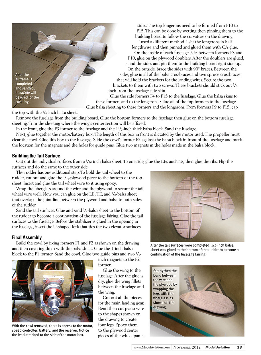
Building the Tail Surface
Cut out the individual surfaces from a 1/16-inch balsa sheet. To one side, glue the LEs and TEs, then glue the ribs. Flip the surfaces and do the same to the other side.
The rudder has one additional step. To hold the tail wheel to the rudder, cut out and glue the 1/16-inch plywood piece to the bottom of the top sheet. Insert and glue the tail wheel wire to it using epoxy.
Wrap the fiberglass around the wire and the plywood to secure the tail wheel wire well. Now you can glue on the LE, TE, and 1/8-inch balsa sheet that overlaps the joint line between the plywood and balsa to both sides of the rudder.
Sand the tail surfaces. Glue and sand 1/4-inch balsa sheet to the bottom of the rudder to become a continuation of the fuselage fairing. Glue the tail surfaces to the fuselage. Before the stabilizer is glued in the opening in the fuselage, insert the U-shaped fork that ties the two elevator surfaces.
Final Assembly
Build the cowl by fixing formers F1 and F2 as shown on the drawing and then covering them with the balsa sheet. Glue the 1-inch balsa block to the F1 former. Sand the cowl. Glue two guide pins and two 1/2-inch magnets to the F2 former.
Glue the wing to the fuselage. After the glue is dry, glue the wing fillets between the fuselage and the wing.
Cut out all the pieces for the main landing gear. Bend then cut piano wire to the shapes shown on the drawing to create four legs. Epoxy them to the plywood center pieces of the wheel pants. Strengthen the bond between the wire and the plywood by wrapping the legs with fiberglass as shown on the drawing.
Glue 1/2-inch balsa pieces to both sides of the center piece to create the wheel well. Make sure that the holes for the metal bracket are aligned. Next, glue the plywood walls of the wheel well to both sides, making sure that the wheel axle and bracket holes are aligned.
Glue 1/8-inch sheet to the outside of the wheel pants and sand them to shape. Insert and glue two brackets into the holes, one in front of the wheel well and the other behind.
Finishing the Model
Cover the Mystery Ship with your favorite material. I used UltraCote. I cut out templates for most of the trims to get the scallops correctly shaped.
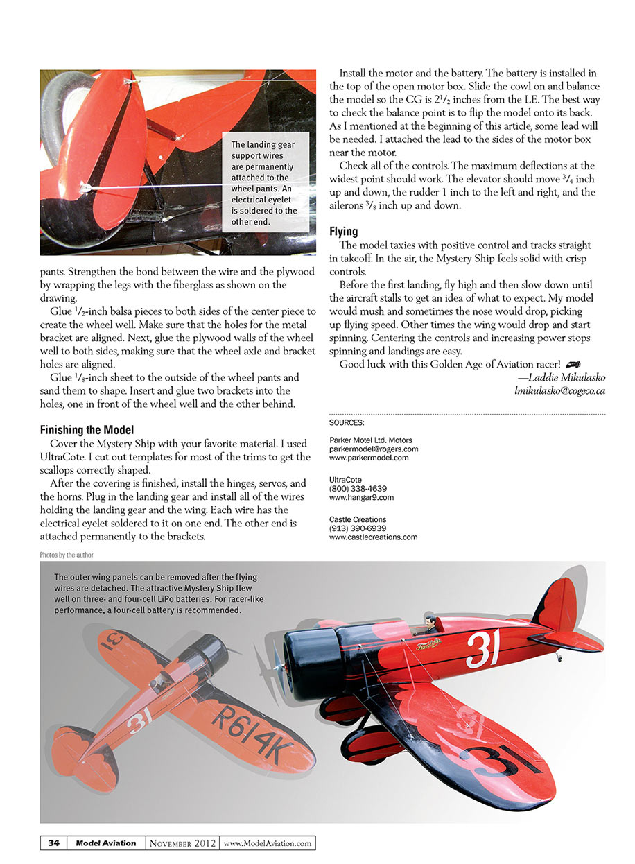
After the covering is finished, install the hinges, servos, and the horns. Plug in the landing gear and install all of the wires holding the landing gear and the wing. Each wire has the electrical eyelet soldered to it on one end. The other end is attached permanently to the brackets.
Install the motor and the battery. The battery is installed in the top of the open motor box. Slide the cowl on and balance the model so the CG is 2-1/2 inches from the LE. The best way to check the balance point is to flip the model onto its back. As I mentioned at the beginning of this article, some lead will be needed. I attached the lead to the sides of the motor box near the motor.
Check all of the controls. The maximum deflections at the widest point should work. The elevator should move 3/4 inch up and down, the rudder 1 inch to the left and right, and the ailerons 3/8 inch up and down.
Flying
The model taxies with positive control and tracks straight in takeoff. In the air, the Mystery Ship feels solid with crisp controls.
Before the first landing, fly high and then slow down until the aircraft stalls to get an idea of what to expect. My model would mush and sometimes the nose would drop, picking up flying speed. Other times the wing would drop and start spinning. Centering the controls and increasing power stops spinning and landings are easy.
Good luck with this Golden Age of Aviation racer!
—Laddie Mikulasko [email protected]
SOURCES:
- Parker Model Ltd. Motors — [email protected] — www.parkermodel.com
- UltraCote — (800) 338-4639 — www.hangar9.com
- Castle Creations — (913) 390-6939 — www.castlecreations.com
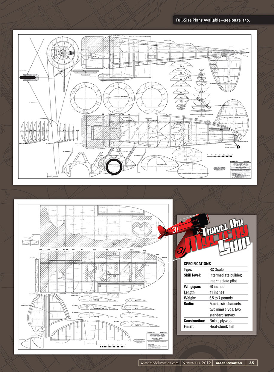
SPECIFICATIONS
- Type: RC Scale
- Skill level: Intermediate builder, intermediate pilot
- Wingspan: 60 inches
- Length: 41 inches
- Weight: 6.5 to 7 pounds
- Radio: Four to six channels, two miniservos, two standard servos
- Construction: Balsa, plywood
- Finish: Heat-shrink film
Transcribed from original scans by AI. Minor OCR errors may remain.

