
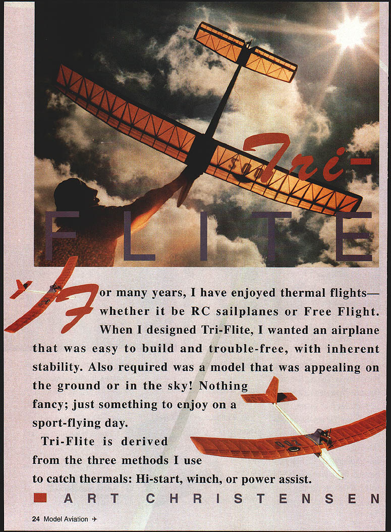
Tri-Flite
For many years I have enjoyed thermal flights—whether RC sailplanes or free flight. When I designed Tri-Flite I wanted an airplane that was easy to build and trouble-free, with inherent stability. Also required was a model that was appealing on the ground or in the sky. Nothing fancy; just something to enjoy on a sport-flying day.
Tri-Flite is derived from the three methods I use to catch thermals: hi-start, winch, or power assist.
Art Christensen
Construction
All of the wood in Tri-Flite may be purchased from Superior Balsa and Hobby Supplies (Tel.: 1-800-488-9525 for orders).
Fuselage
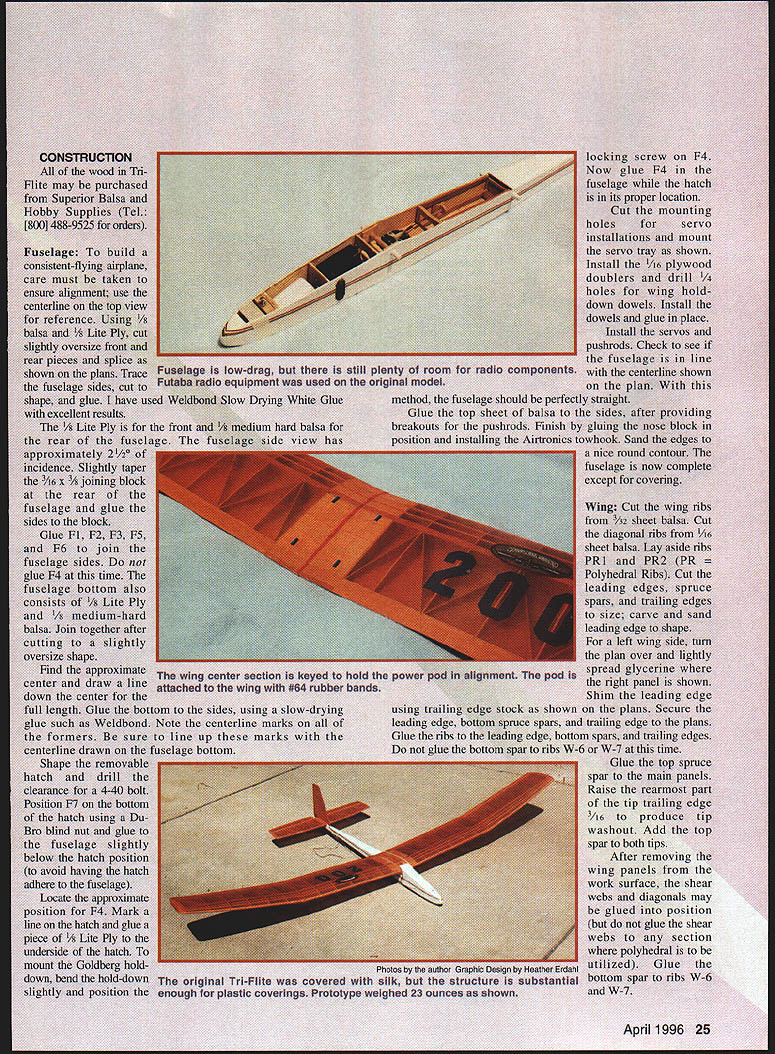
To build a consistent-flying airplane, care must be taken to ensure alignment. Use the centerline on the top view for reference.
- Materials:
- 1/8" balsa and 1/8" lite plywood for front and rear pieces (cut slightly oversize and splice as shown on the plans)
- 3/8" lite plywood for the front former
- 1/8" medium-hard balsa for the rear of the fuselage
- 3/16" x 3/8" joining block (taper slightly at the rear)
- 1/8" lite ply or medium-hard balsa for fuselage bottom
- Weldbond (slow-drying white glue) recommended
- Steps:
- Trace and cut fuselage sides to shape; glue pieces together. Ensure alignment using the centerline.
- The fuselage side view has approximately 2-1/2° of incidence. Slightly taper the joining block and glue the sides to it.
- Glue formers F1, F2, F3, F5, and F6 to join the fuselage sides. Do not glue F4 initially.
- Join the fuselage bottom (after cutting slightly oversize). Draw a centerline down the full length and glue the bottom to the sides, lining up centerline marks on all formers.
- Shape a removable hatch; drill clearance for a 4-40 bolt. Position F7 on the bottom of the hatch using a Du-Bro blind nut and glue the blind nut slightly below the hatch location to avoid adhesion issues.
- Locate the approximate position for F4, mark the hatch line, glue a piece of 1/8" lite ply to the underside of the hatch to mount the Goldberg hold-down. Bend the hold-down slightly so the locking screw engages F4. Glue F4 in place while the hatch is properly positioned.
- Cut mounting holes for servos and mount the servo tray. Install 1/16" plywood doublers and drill 1/4" holes for wing hold-down dowels. Install dowels and glue in place.
- Install servos and pushrods. Check that the fuselage aligns with the centerline on the plan; the fuselage should be straight.
- Glue the top sheet of balsa to the sides after providing breakouts for the pushrods. Finish by gluing the nose block in position and installing the Airtronics tow hook. Sand edges to a nice round contour.
The fuselage is now complete except for covering.
Wing
- Materials:
- Wing ribs: 3/32" sheet balsa
- Diagonal ribs: 1/16" sheet balsa
- Leading edges, spruce spars, and trailing edges to size
- PR1, PR2 = polyhedral ribs
- Plywood gussets PG1, PG2
- Shear webs, diagonals, hard balsa inserts, 1/8" square turbulators
- 1/16" light balsa sheet for center section planking
- Steps:
- Cut wing ribs from 3/32" sheet balsa; cut diagonal ribs from 1/16" sheet balsa. Set aside PR1 and PR2 ribs.
- Cut leading edges, spruce spars, and trailing edges to size; carve and sand the leading edge to shape.
- For the left wing panel, turn the plan over and lightly spread glycerine where the right panel is shown to ease assembly. Shim the leading edge as shown on the plans.
- Secure spars and trailing edge to the plans. Glue ribs to the leading edge, bottom spars, and trailing edges. Do not glue the bottom spar to ribs W-6 or W-7 at this time.
- Glue the top spruce spar to the main panels. Raise the rearmost part of the tip trailing edge 3/16" to produce tip washout. Add the top spar to both tips.
- After removing the wing panels from the work surface, glue shear webs and diagonals into position (do not glue shear webs in locations where polyhedral is to be installed).
- Glue the bottom spar to ribs W-6 and W-7.
- Join tips to main panels using plywood gusset PG1. Join main panels together using plywood gusset PG2.
- Insert hard balsa between spruce spars at the tips of the main panels as shown. Glue PR1 and PR2 ribs in place.
- Place 1/8" square turbulators in rib notches and glue in place.
- Plank the bottom and top center section with 1/16" light balsa sheet. Notch to install the trailing edge center section (spruce as specified). Glue solid balsa to both tips. Complete shear web installation at the polyhedral joints.
Stabilizer
The stabilizer is conventional construction.
- Use medium-hard 1/4" square leading edge stock.
- Note hinge locations and be sure to allow 1/4" between center ribs for elevator motion.
- Use 1/8" balsa for the elevator as shown on the plans.
- Mount the elevator control horn on the right side (top view).
Rudder
Construct the rudder similar to the stabilizer and elevator.
- Note hinge location and control horn placement as shown on the plans.
- Allow the required clearance where the rudder leading edge enters the stabilizer (cut a slot 3/8" x 1/4" for rudder leading edge entry into the fuselage).
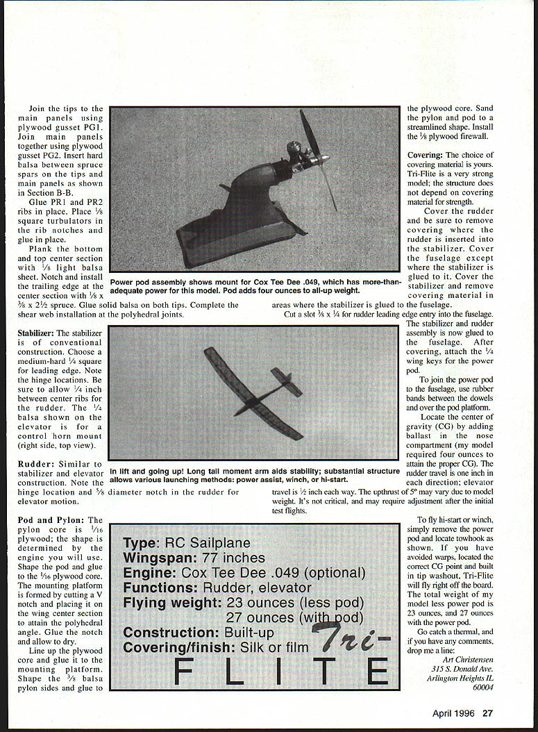
Pod / Pylon
- Pylon core is 1/16" plywood shaped to suit the engine you will use.
- Shape the pod core and glue a 1/8" plywood core mounting platform formed by cutting a V-notch to accept the wing center section to attain the polyhedral angle. Glue and allow to dry. Line up the plywood core and glue the mounting platform.
- Shape pylon sides from 3/16" (or 3/32" as specified on the plan) balsa and glue. Cut a diameter notch for the rudder plywood core.
- Sand the pylon/pod to a streamlined shape. Install a 1/16" or 1/8" plywood firewall as specified on the plans.
- To join the power pod to the fuselage, use rubber bands between the dowels and over the pod platform.
Covering
The choice of covering material is yours. Tri-Flite is a very strong model; the structure does not depend on the covering material chosen.
- Cover the rudder and be sure to remove covering where the rudder is inserted into the stabilizer.
- Cover the fuselage except where the stabilizer is glued to it. Cover the stabilizer and remove covering material in areas where the stabilizer is glued to the fuselage.
- After covering, attach the 1/4" wing keys for the power pod.
Flying and Setup
- To fly hi-start or winch, simply remove the power pod and locate tow hook as shown on the plans.
- If you have avoided warps, located the correct CG point, and built in tip washout, Tri-Flite should fly right off the board.
Recommended settings and notes:
- Rudder travel: 1/2" each direction
- Elevator travel: 3/8" each way
- Upthrust: approximately 5° (may vary with model weight; not critical and may require adjustment after initial test flights)
- Locate the center of gravity (CG) by adding ballast in the nose compartment (example: the author’s model required four ounces to attain the proper CG).
Specifications
- Type: RC sailplane
- Wingspan: 77"
- Engine: Cox Tee Dee .049 (optional)
- Functions: Rudder, elevator
- Flying weight: 23 oz (less pod); 27 oz (with pod)
- Construction: Built-up
- Covering/finish: Silk or film
Go catch a thermal, and if you have any comments, drop me a line:
Art Christensen 315 S. Donald Ave. Arlington Heights, IL 60004
Transcribed from original scans by AI. Minor OCR errors may remain.

