
Trimming From the Ground Up Part 2
by Dean Pappas
Picking Up Where We Left Off
In the first installment of this "Trimming From the Ground Up" series we dealt with pitch trim. As it turns out, it's a whole lot more than just moving the transmitter trim lever a few clicks or beeps until the model flies without climbing or diving.
Airplane trimming is similar to setting up a race car: when a crew chief says the "race car was fast right out of the trailer," he really means the team was able to run through the entire setup checklist quickly. That usually means few or no adjustments were necessary, but it doesn't mean every little thing wasn't checked.
There aren't all that many things to check when test-flying a new airplane, but if one of the tests described here shows a problem, you're working harder than necessary when flying your airplane. If your model is intended for training, that's a bad thing. If you're a more advanced flier, you're simply missing opportunities to fly better and look better.
The mission of this series is to describe tests and corrective actions in a systematized way to help you make your airplane fly better. None of it is hard, and you don't have to tackle it all at once. For example, you can investigate pitch behavior separately from an unfortunate tendency to turn left immediately after takeoff.
Engine Right Thrust
I've already written about the adjustment of downthrust; now it's time to discuss right thrust.
Some years ago I attended a Scale Masters Qualifier meet. One competitor was flying a Cessna L-19 Bird Dog. We were taking off from right to left that day, and every takeoff veered left—over the flightline, the pits, and the parking area. This is what happens when the right thrust is not correctly set up.
Full-scale pilots emphasize the proper application of right rudder to counteract "torque" on takeoff. That is an excellent skill to develop, but the fix for most aeromodels is to set the proper amount of right thrust in the engine. This minimizes rudder corrections during takeoff, which is especially important for beginners who are still learning coordinated control.
Before describing how to add right thrust and how to test its correctness, note that right-thrust trimming is a compromise: it counters an airspeed-dependent problem. As it turns out, it's usually a good compromise.
The Application
At low and part throttle the effect of right thrust is minimal. We set right thrust to straighten out a full-power takeoff climb and accept the small, unwanted influence it has at cruise. In the glide right thrust has practically no effect, so it's not an issue.
You don't want to climb so steeply that the model stalls, but you should climb as steeply as your horsepower allows. The airplane will lose airspeed during the climb and may become more easily influenced as control surfaces lose effectiveness. If the model deviates to the left, add more right thrust. Retrim for straight-and-level flight (probably just a click of rudder) and repeat the test until the model climbs straight.
If the airplane deviates to the right during climb, you have too much right thrust (this is rare). Adjust in small increments—one degree at a time—and repeat the test. Most airplanes need about 2°–3° of right thrust; a few require more.
The Right-Thrust Test
- Trim the model to fly straight at cruise power.
- Point the airplane straight away from you, headed directly into the wind or directly downwind. Avoid crosswind alignment—sideward drift can mask the turn you're checking for.
- Add full throttle and smoothly pull up into a climb at the same angle as your steepest post-takeoff climb.
- Observe the climb: if it turns left, add right thrust; if it turns right, reduce right thrust; retrim and repeat until it climbs straight.
A Little Theory
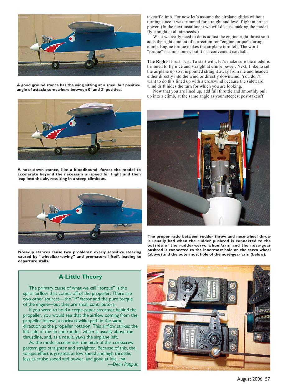
The primary cause of what we call "torque" is the spiral airflow off the propeller. There are two smaller contributors—the P-factor and the engine's pure torque—but the spiral slipstream is dominant.
If you held a crepe-paper streamer behind the prop, you'd see the airflow follow a corkscrew path in the propeller rotation direction. This spiral strikes the left side of the fin and rudder (usually above the thrustline) and yaws the airplane left.
As the model accelerates, the corkscrew pattern straightens. Thus, the torque effect is greatest at low speed and high throttle, less at cruise, and gone at idle.
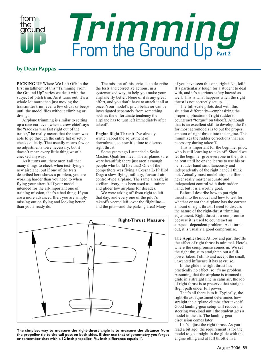
Right-Thrust Measurement
- Easiest practical method: measure the distance from each propeller tip to the tail post.
- With a 12-inch prop, a 3/16-inch difference equals 1° of right thrust. Three degrees equals 9/16-inch difference.
- With a 16-inch prop, the ratio is about 1/4 inch per degree.
Start with the kit's recommended setting if available; if not, begin around 2½° and fine-tune.
An Alternate Down-Thrust Check for Advanced Sport Models
For sport designs with semi-symmetrical or symmetrical airfoils that aren't intended to be as stable as trainers, try this hands-off downthrust test:
- Establish a hands-off level pass about 50 feet up on the far edge of the runway so you can observe the airplane clearly.
- While trimmed to fly straight at cruise, suddenly reduce power to idle.
- Observe the immediate response (the airplane will still be at cruise speed for a second or two).
- If the nose twitches up and the plane slows into a glide, you have too much downthrust.
- If the nose drops slightly and the airplane immediately assumes a fast, nose-down glide, you need more downthrust—the elevator trim had been compensating for an engine-induced climb.
- If the downthrust is correct, the airplane will continue straight for a second or two and then gradually settle into the glide angle.
You may also see the effect when power is applied suddenly: too much required downthrust can produce an abrupt nose-up when you firewall the throttle for a go-around—dangerous for heavy scale models.
Landing Gear
An airplane that rolls straight and responds predictably to steering input will be easier to fly. Straight takeoffs and smooth landings that roll to a straight stop make you look skillful. Zigzagging across the runway will get attention for the wrong reasons.
Most trainers use tricycle landing gear, so we'll cover those first, then tail-draggers.
Tricycle-Gear Problems and Fixes
- Excessive nose-wheel steering throw: The model doesn't need to turn within its wingspan; a minimum turning radius of roughly 15 feet with full rudder is sufficient—this often equates to only about 5° of nose-wheel deflection. Achieve this by connecting the linkage to the innermost hole of the servo arm and the outermost hole on the nose-strut steering arm. Consider drilling a hole closer to the servo center post if needed.
- Flexible steering linkage: A springy linkage gives poor, inconsistent control and can let the nose wheel twist at touchdown, causing the airplane to "curtsy" and potentially tear out the firewall. Use a stiff, straight linkage—0.050-inch-diameter wire in a plastic tube works well if the run is nearly straight. Avoid sharp bends and binding.
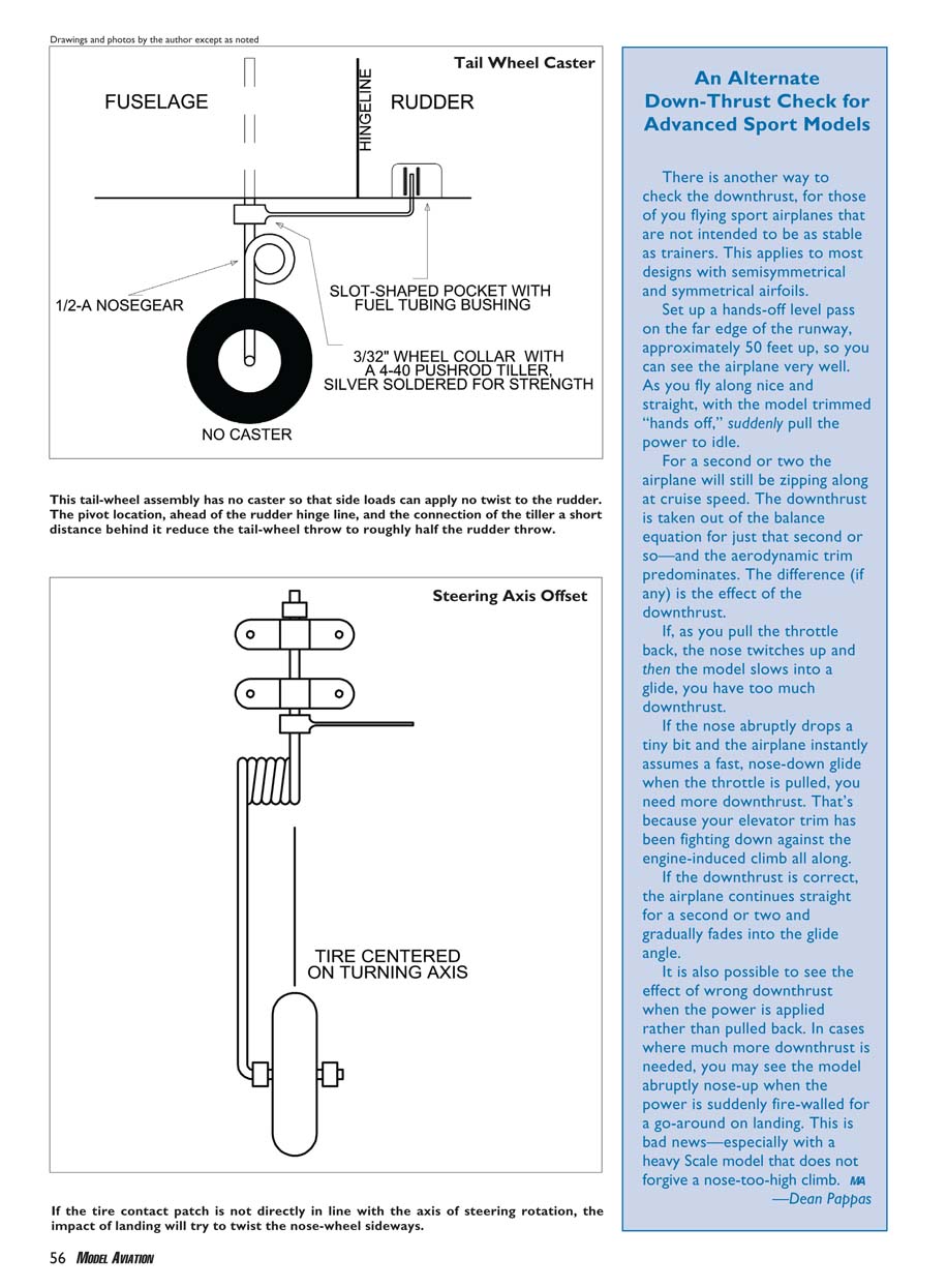
- Nose-wheel alignment: From the front, the tire's contact patch should be directly in line with the axis of steering rotation. Any offset will try to twist the nose wheel on bumps and will stress servos.
- Nose-high vs. nose-down ground attitude:
- Nose-down forces a longer ground roll until the elevator becomes effective, often resulting in a sudden, too-steep liftoff and loss of airspeed.
- Nose-up causes bouncing on landing and wheelbarrowing on takeoff.
- Ideal attitude: wing chord (or flat bottom) within a few degrees of level with the ground. A well-set-up trainer will lift off with just a slight touch of up-elevator when the airspeed is right.
- Fore-and-aft location of main gear: If main gear is too far aft the nose wheel carries too much weight, leading to sensitive high-speed steering and long takeoff runs requiring large up-elevator inputs. The ideal main-gear location makes the nose wheel light when the tank is empty; the model should almost sit on its tail with an empty tank. Bend or shim the main gear forward if necessary.
- Overly springy landing gear: Some wire gear supplied in kits can be too springy for the airplane's weight, leading to bounce. Solutions include wire and rubber-band reinforcements or replacing the gear with a stiffer aluminum unit.
Attitude Adjustment
The airplane's ground attitude strongly affects required up-elevator for liftoff. Check the stance and main-gear position before concluding that the elevator trim or CG is the culprit. A proper stance prevents sudden liftoffs and wheelbarrowing.
So Why Are You Dragging Your Tail Around?
Tail-draggers face many of the same issues as tricycle-geared models, with special emphasis on main-gear fore-and-aft location:
- If the mains are too far aft, the airplane can nose-over easily.
- If the mains are too far forward, you get the high-speed wheelbarrow problem—difficult to keep straight at high speed before liftoff.
For tail-wheel steering:
- If the airplane is hard to keep straight on takeoff due to overcontrol, reduce tail-wheel throw. With "two springs" steering linkages, hook up to the inner end of the rudder horns and the outer end of the tail-wheel horns to reduce throw.
- With a "tiller-arm" linkage (a single wire along the rudder attached with a clip), move the tail-wheel pivot forward and reposition the clip on the rudder to reduce throw.
For nose-wheel strut stiffness on light airplanes, a spring coil or a 3/32-inch-diameter music-wire 1/2-A nose-wheel strut works well. The goal is positive, predictable steering without excessive compliance.
Takeoff, Climbout, and the CG
- Nose-heavy: A severely nose-heavy model requires lots of up-elevator to lift the nose wheel and break ground. This can also be caused by landing-gear position or ground stance. If the CG is correct, holding a constant climb angle is easier. If the plane is nose-heavy you may need a quick elevator adjustment just after liftoff.
- Tail-heavy: On takeoff, tail-heaviness often shows as climbouts that quickly become too steep and can induce pilot-induced oscillation (PIO). Tail-heavy airplanes also tend to snap roll. Temporarily moving the CG forward can confirm whether the airplane will fly a smoother departure.
Pitch Trim Revisited
Now that the airplane is departing nicely, it’s time for Part 2 of the "From the Ground Up" basic trim series to help you depart smoothly and trim for good behavior in all flight regimes. I'll wrap things up in the next installment.
Dean Pappas [email protected]
Transcribed from original scans by AI. Minor OCR errors may remain.

