
TURBINE MODELING MADE EASY
By Pete Oochroma
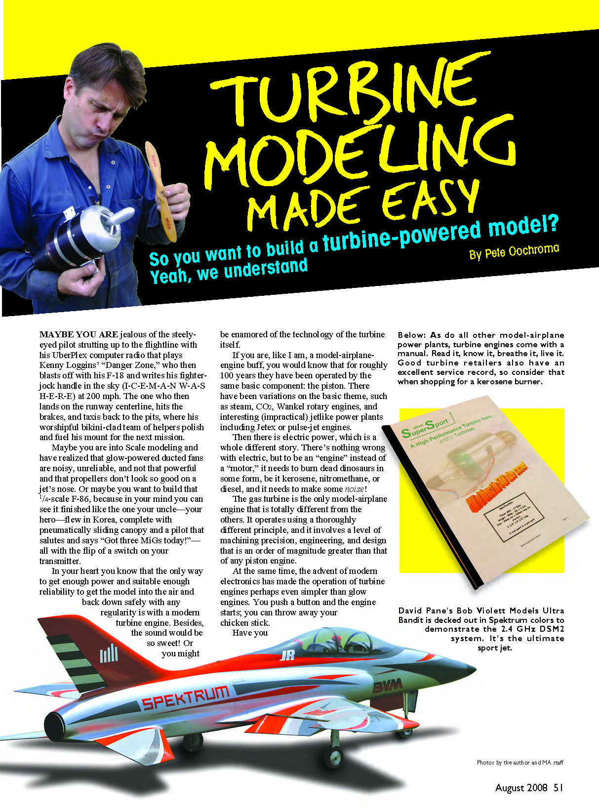
So you want to build a turbine-powered model? Have you avoided trying turbines because you thought they were too complicated or too expensive? They aren't. In this article I'll cover the basics: the engine, fuel system, airframe, electronics, the AMA waiver process, safety—the whole thing. If you can build and fly a 60-size RC aerobatic model, you can do this.
You may have heard rumors that flying a turbine costs $20,000. Some do, but the average for many models is lower. With a simple airframe and new retail parts, you can get a turbine-powered model flying for roughly $3,500. If you find a good used engine, you can do even better. When you step up to a fully detailed scale model later, you'll already own most of the equipment.
Be realistic about costs and component quality. A turbine model is not the place to skimp on servos, linkages, or fittings. Crashes can be much worse than with propeller airplanes—total losses and fire are real possibilities. Use good equipment and be careful when saving money.
ALL ABOUT TURBINES
There are many brands of popular model turbines. For your first engine, buy new with a full warranty and product support. Being able to call a knowledgeable representative can save you a crash or a ruined engine. Many used engines are bargains, but they often have odd starting systems or lack support. Once you understand modern, full-auto-start turbines, you'll be better prepared to evaluate used units.
When your new engine arrives, you may be confronted with a long manual and many components. Read on—this section walks through the common components, what they do, and how to hook them up.
Temperature Probe
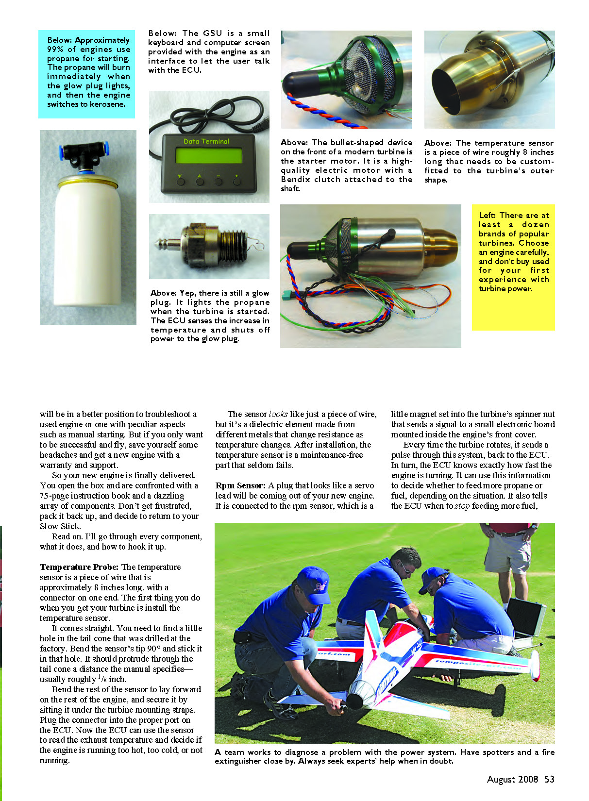
- The temperature sensor is a small probe, about 8 inches of wire with a connector.
- Install it in the factory-drilled hole in the tail cone. Bend the tip 90° so it protrudes roughly 1/8 inch (or per the manual).
- Lay the rest of the sensor forward and secure it under the turbine mounting straps.
- Plug it into the ECU. The ECU uses it to read exhaust temperature and to manage starting and safety limits.
- The probe is a dielectric element that changes resistance with temperature and is typically maintenance-free.
RPM Sensor
- A connector that looks like a servo lead comes out of the engine; it connects the ECU to an RPM sensor.
- The sensor is a magnet set in the spinner nut that sends pulses to a small board inside the front cover each rotation.
- The ECU uses RPM data to control fuel flow and the starting sequence.
- Plug the connector into the correctly marked ECU port. No routine maintenance is needed.
Glow Plug
- Turbine glow plugs ignite propane during starting.
- Many turbines require you to modify the glow plug when it arrives: gently pull the coil out slightly so the heated element projects deeper into the engine where the gas is.
- Test the plug with a glow driver before reinstalling. Do not over-tighten the threads.
- Wire the glow plug per the manufacturer’s harness: the lead with the washer goes under the plug, the other on top. Plug into the ECU.
- The ECU powers and monitors the plug; glow plugs last a long time but will eventually need replacement.
Solenoids
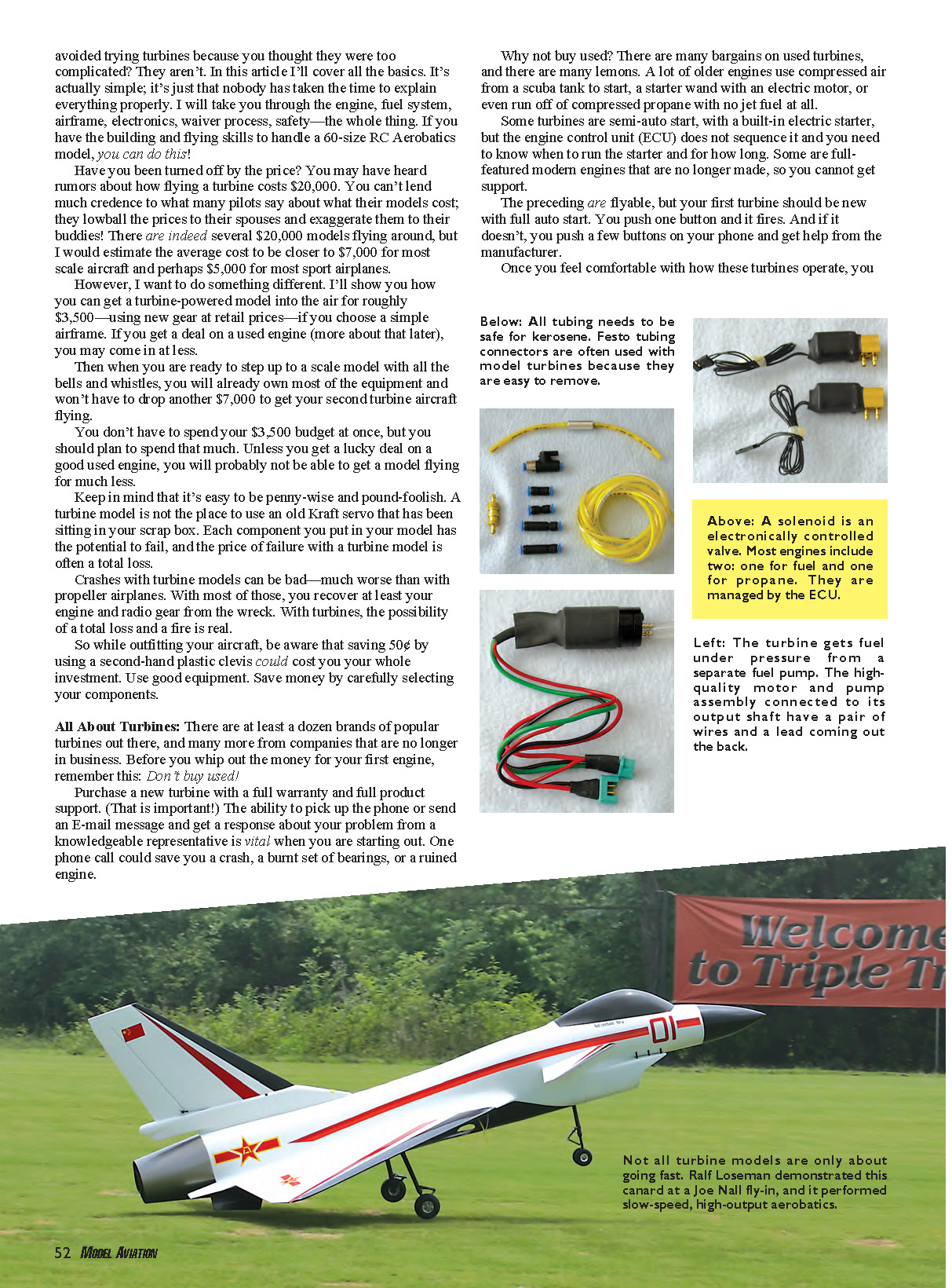
- Solenoids are electronically controlled valves. Most engines include two: one for fuel and one for propane.
- Mount them securely in the airframe and plug them into their ECU ports. Plumb them into the fuel and propane systems.
- The ECU opens the propane solenoid during starting; the fuel solenoid can act as a safety shutoff.
- Solenoids are mostly maintenance-free but can stick, especially if frozen propane gets into the lines. You can usually hear them click when activated.
Starter Motor
- The starter is the bullet-shaped motor on the front with a Bendix clutch. When powered, a cone extends and engages the spinner nut to spin the turbine.
- A small O-ring in the starter cone provides friction; it’s a wear item but easy to replace.
- The ECU controls the starter during the automated start sequence. Plug it into the correct ECU port and let the ECU manage it.
Fuel Pump
- The turbine receives fuel under pressure from a small electric pump. Mount it securely and away from sensitive electronics if possible.
- The pump usually has a loop of tubing with fuel in place to prevent running dry; if it does run dry, you must reprime it.
- Filter fuel before it reaches the pump; particles can damage the internal gears.
- Mount, plumb, and plug the pump into the ECU; the ECU controls timing during start/run.
ECU (Engine Control Unit)
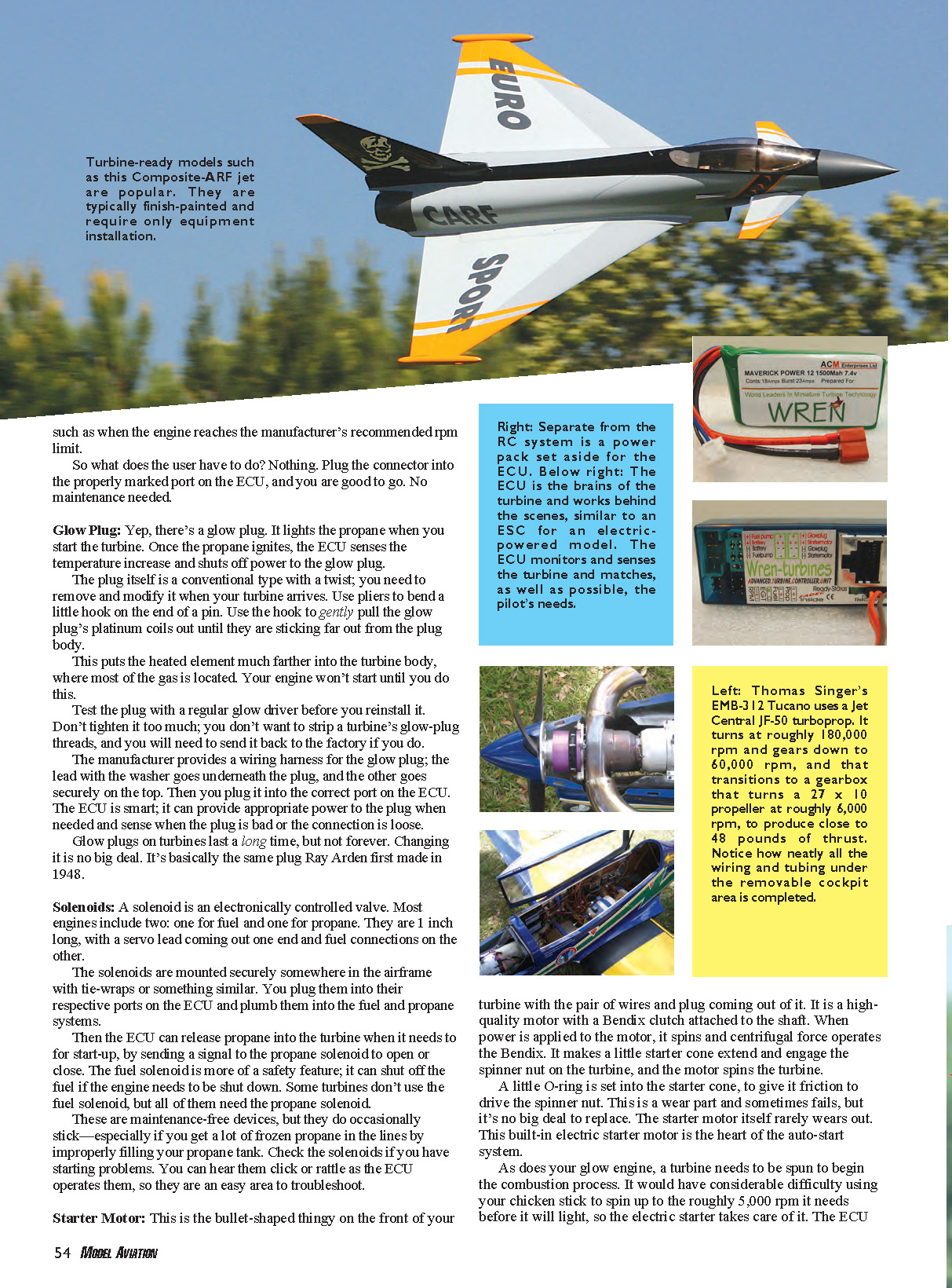
- The ECU is the brain. Plug it into the receiver and program it to learn your throttle stick's high and low positions (follow the manual).
- The ECU sequences starter, glow plug, fuel pump, solenoids, and monitors RPM and temperature. It also logs starts, run times, and temperatures.
- Do not change engine parameters unless instructed by the manufacturer or a representative.
Ground Support Unit (GSU)
- The GSU is a small screen/keyboard that connects to the ECU for programming or data readout.
- Use it to check last-flight data or troubleshoot. Avoid changing parameters unless instructed by factory support.
ECU Battery
- The ECU battery powers the ECU and devices it drives: starter, glow plug, pump. Commonly a six-cell NiCd/NiMH; some newer systems use 2S LiPo.
- Expect at least five flights per charge; top it off regularly. A charger is usually not included.
FOD Guard
- FOD (Foreign Object Damage) guards prevent debris from entering the intake. Some engines ship with factory guards.
- A simple homemade guard can be made from a tea strainer with a starter hole. Attach with silicone.
- Consider aircraft configuration: chin scoops (e.g., F-16) are prone to debris intake.
Plumbing
- Tubing and Festo connectors: Use kerosene-safe tubing (Tygon is common). Festos are convenient quick-connect fittings; your engine package should include several types.
- One-way valves have flow arrows—install correctly. Include a manual shutoff valve accessible from the airframe to cut fuel quickly in an emergency.
- Fuel tanks: Modern turbines are fuel-efficient. For 54-class engines, 50–70 ounces is generally sufficient.
- Use kerosene-safe stoppers and Tygon tubing. Use large-diameter brass tube through the stopper, 3/32" Tygon elsewhere.
- Secure clunk lines and fittings with clamps, safety wire, or small tie-wraps.
- Cut tubing square with a razor blade to avoid leaks.
- Air trap (header tank): Bubbles are the enemy. Use a header tank with an air-trapping pickup (commercial options like the BVM UAT are popular).
- A simple 6-ounce tank with a centered pickup can work if tanks are kept at least half full.
- Don’t omit a header tank—clunks alone may not be sufficient in practice.
- Filters: Install the supplied high-quality filter between tanks and pump. Also filter fuel when filling your can and use in-line automotive-style filters.
Feeding Your Turbine
- Propane:
- Propane assists starting because kerosene needs higher temperatures to atomize. Coleman Powermix (propane + butane) often works best.
- Engines include an onboard propane canister, a one-way fill valve, and tubing to the solenoid. Fill the onboard bottle before starting. The ECU actuates the propane solenoid during start.
- Oil:
- Bearings spin at very high RPM and must be lubricated. Modern turbines use oil mixed into the fuel; a small amount is diverted to the bearings.
- Use proper turbine oil (available from airports or suppliers like oil-store.com). Typical mix is 1 quart oil to 5 gallons fuel, but follow your engine manual for grade and ratio.
- Fuel:
- Kerosene is the standard. Jet A is available at airports (more expensive). K1 kerosene or clear kerosene from home-improvement stores is a convenient, clean option.
- Filter fuel carefully—station pumps can be dirty.
- Fueling:
- Use a dedicated fuel can. Commercial fuel containers (e.g., Jersey Modeler) often include an electric pump, battery, filters, and a return line to prevent spills while filling.
- A good fueling setup is a modest, worthwhile investment.
RADIO SETUP
Servos
- Use high-quality servos. Digital servos are popular for torque and position-holding.
- Mini digital servos (60+ oz-in) are common for ailerons; flaps usually require standard-size servos with 120+ oz-in.
- Elevators should use the best servo you can afford (e.g., 150 oz-in+).
- Nose-gear steering should use standard servos with metal gears.
- Avoid rubber isolation grommets; mount servos rigidly with screws and wide washers to prevent slop and reduce flutter risk.
- Most kits supply hardwood blocks or brackets for solid mounting.
Linkages
- All linkages must be strong and free of slop. Drill correct-sized holes for clevises—do not enlarge with an X-Acto blade.
- Use 4-40 hardware and heavy-duty horns. Pop-on ball links are not recommended; Robart horns with built-in ball links are a good choice.
- Avoid E/Z Connectors on primary control surfaces. Use a screw-in clevis on one end and a soldered clevis on the other for security and some adjustability.
Servo Leads
- Long runs of servo wire are common. Use heavy-gauge leads and good connectors. Avoid running power leads alongside long signal leads to minimize electrical noise.
- If desired, use ferrite rings on extensions. TanicPacks provides a wide selection of extension leads and Y harnesses.
Receivers
- Use a high-quality receiver. PCM or PPM will work; 2.4 GHz spread-spectrum radios are excellent for turbines.
- A metal whip antenna helps keep reception clear of metal and wiring.
- The receiver/ECU combination must have a throttle fail-safe; AMA requires engine shutdown on signal loss to reduce fire risk. Many ECUs implement this internally.
Radio Batteries and Backing
- Use redundant power systems for safety. Two batteries plugged into separate receiver inputs are simple redundancy.
- Consider battery-backing systems or power buses that isolate servo and receiver power.
- Two five-cell packs are a common, reliable choice; they provide strong servo performance and redundancy.
THE AIRFRAME
Rudder
- AMA requires turbine models to have working rudders. Rudders provide important control near the pits and are not heavy or complicated—install one.
Retracts and Struts
- Most turbine jets use pneumatic retracts with shock-absorbing struts. Wire legs are unsuitable for turbine model weights.
- Use a proven plug-and-play retract/wheel/brake system made for your model when possible. Custom fitting can require machinist services.
- For your first turbine, consider fixed gear (e.g., JetMach 60) to avoid retract maintenance.
Brakes
- Brakes are required by AMA. Pneumatic brake systems are the common choice.
- Components include a Schrader-style fill valve, an onboard air tank, a servo-operated brake valve, and wheel brakes (O-ring expanding against a drum).
- Use square cuts on tubing and avoid plastic T fittings to reduce leaks.
- Electric pumps speed pressurizing; an automotive 12V pump with a gauge works fine.
- Valve options range from simple on/off to proportional systems (e.g., BVM Smooth Stop). Electronic valves are available but can consume more air.
THE AMA WAIVER
- The AMA Turbine Waiver provides AMA coverage (insurance) while flying turbines. AMA coverage supplements homeowner insurance; many clubs and meets require it.
- To obtain the waiver:
- Fly in front of two authorized people: one must be an AMA Contest Director (CD) who holds a turbine waiver; the other may be any waiver holder as witness.
- Both signatures, and yours, must be notarized. The signers attest you have the skills to fly a turbine.
- The CD decides what model you should fly for the sign-off.
- Jet meets often schedule practice days—good times to get signed off. Don’t do waiver checks in front of spectators.
- Send the notarized form to AMA Headquarters in Muncie, Indiana. The AMA website lists turbine CDs and waiver holders.
FLYING YOUR TURBINE
Preflight and Starting
- Build a simple test bench to practice starting, or install the turbine in the airframe—your choice.
- Ensure good charge on receiver and ECU batteries. Fill fuel tanks but use the manual shutoff valve to prevent excess fuel in the engine.
- Excess fuel in the engine can cause a "wet start" with flames. If this happens, pick up the model, point the nose up, and shake fuel from the tailpipe.
- Fill the onboard propane bottle before starting. Use a GSU to monitor the start sequence.
- Typical start sequence: move throttle stick up and down three times (engine-specific—follow the manual). The starter spins the turbine, propane is delivered and ignited by the glow plug, then when temperature and RPM are reached the fuel pump engages and kerosene combustion begins.
- The ECU ramps the engine to idle (often tens of thousands of RPM) and then hands control to your transmitter. The automated sequence usually takes 10–20 seconds.
- To shut down, lower throttle trim fully. The ECU may cycle the starter occasionally to keep airflow for cooling until temperature is safe.
Fire Extinguishers and Safety
- Always have a fire extinguisher nearby when starting the turbine. Water-based extinguishers are preferable to dry-chemical types (which make a mess).
- Keep the local fire department number handy. For club use, consider a 5-gallon backpack-style pump extinguisher for grass fires.
- Never start a turbine without a charged extinguisher at hand. The AMA requires it.
Field Selection and Etiquette
- Not all fields welcome turbines. Reasons include short runways, nearby neighbors, fire risk, or local airspace concerns.
- Be considerate: turbines are louder and perceived as more dangerous by the public. A single irresponsible flight can jeopardize flying privileges for everyone.
- Visit your club, introduce yourself, and educate members. Be gracious and work with club rules.
- Flying at a local full-scale airport is an alternative—get permission, coordinate with airport operations, and use a spotter.
- Always get landowner permission and respect local fire bans and dry conditions.
Jet Rallies
- Attend jet rallies as a spectator to learn. You’ll see many flights, observe models and setups, and meet experienced fliers who can help you.
RUNNING AND MAINTENANCE
- Modern turbines and ECUs are sophisticated and largely maintenance-free. Most manufacturers recommend an inspection every ~25 hours.
- The GSU will report issues like bad glow plugs, fuel starvation, or sensor errors.
- Use correct oil, maintain clean fuel and filters, and inspect solenoids, starters, and plumbing regularly.
SOURCES / CONTACTS
- BVM — (407) 327-6333 — www.bvmjets.com
- Oil-Store.com — http://oilstore.stores.yahoo.net/
- Jersey Modeler — (732) 240-0138 — www.jerseymodeler.com
- Laser Design Services — (972) 772-4326 — www.laser-design-services.com
- TanicPacks — (800) 728-6976 — www.tanicpacks.com
- JetLegend — www.jetlegend.com
- Du-Bro — (800) 848-9411 — www.dubro.com
- Robart Manufacturing — (630) 584-7616 — www.robart.com
I hope this sheds light on model turbines. They can be intimidating at first, but once you break everything down, they are highly rewarding—providing performance, realism, and unforgettable sound.
Pete Oochroma [email protected]
Sources:
- Information for turbine-waiver holders: www.modelaircraft.org/news/turbwaiv.aspx
Transcribed from original scans by AI. Minor OCR errors may remain.

