
Turbine Time
Delmar Ellis
Background and airframe selection
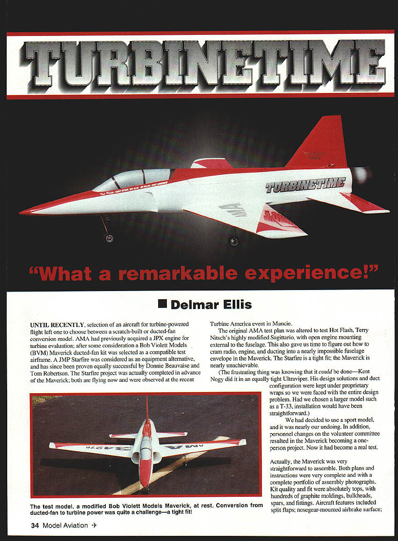
Until recently, selection of an aircraft for turbine-powered flight left one to choose between a scratch-built or ducted-fan conversion model. AMA had previously acquired a JPX engine for turbine evaluation; after some consideration a Bob Violett Models (BVM) Maverick ducted-fan kit was selected as a compatible test airframe. A JMP Starfire was considered as an equipment alternative, and has since been proven equally successful by Donnie Beauvaise and Tom Robertson. The Starfire project was actually completed in advance of the Maverick; both are flying now and were observed at the recent Turbine America event in Muncie.
The original AMA test plan was altered to test Hot Flash, Terry Nitsch's highly modified Sagittario, with open engine mounting external to the fuselage. This also gave us time to figure out how to cram radio, engine, and ducting into a nearly impossible fuselage envelope in the Maverick. The Starfire is a tight fit; the Maverick is nearly unachievable.
The frustrating thing was knowing that it could be done—Kent Nogy did it in an equally tight Ultraviper. His design solutions and duct configuration were kept under proprietary wraps so we were faced with the entire design problem. Had we chosen a larger model such as a T-33, installation would have been straightforward.
We had decided to use a sport model, and it was nearly our undoing. In addition, personnel changes on the volunteer committee resulted in the Maverick becoming a one-person project. Now it had become a real test.
Kit quality and initial assembly
Actually, the Maverick was very straightforward to assemble. Both plans and instructions were very complete, including a complete portfolio of assembly photographs. Kit quality and fit were absolutely tops, with hundreds of graphite moldings, bulkheads, spars, and fittings. Aircraft features included:
- split flaps
- nosegear-mounted airbrake surface
- full top hatch openings, nose to aft fuselage
- graphite spars and plug-in receptacles
- air-actuated wheel brakes
- tip tanks (later deleted)
The model was built per instructions except for substitution of hand-carved wingtips instead of tip tanks and use of medium-weight glass on the main wings.
Key redesign considerations
The key redesign problem was providing an adequate flowpath and fabricating components. Considerations included space utilization, stable and acceptable performance, adequate cooling, and installation.
The first attempted breakthrough occurred with procurement of a graphite engine shroud, imported from an English design and intended to fit into a T-33. You couldn't even get it into the Maverick because of the diameter. And the length would place the engine well aft of the target location, and behind the top hatch opening. This also placed the CG well aft of limits, considering engine weight.
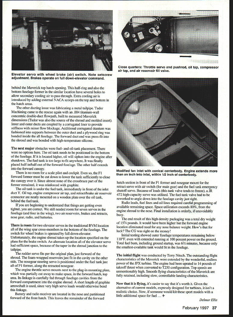
Alternatives were to cut the shroud up and reduce size or refabricate one in the required size. The rework approach was tried first, at least to determine minimum size limits. This resulted in a shroud of minimum length and diameter, placing the engine at maximum forward location and with minimum shroud opening—just barely allowing the engine to be inserted through the opening (with a little bending). One good feature was the direct fit of the shroud to the BVM fan inlet assembly. The fan flowpath inner hub was trimmed forward to the strut and a conical centerbody was installed to fair flow. The engine is actually mounted so far forward as to extend into the inlet more than one inch and to within 1/2 inch of the aft end of the centerbody.
The engine was mounted on standard JPX split rings with wing extensions to both sides. BVM servo mount brackets (graphite L-section structures) were glued to the fuselage sides and to 1/4" plywood backup plates. This formed bolt attachment ledges to bolt the engine strap mounts.
Since the strap mounts extend outward through the shroud at the horizontal split line, the shroud hatch was cut to form a semicircle. This worked fine, except that the hatch could not be hinged — it would interfere with the Maverick top hatch. An elastic double-strap restraint using Velcro quick-release was adapted (not an original idea) for shroud hatch attachment.
Even with the shroud minimized in size, fit is extremely tight. With the engine installed, the shroud hatch interfered with the engine throttle valve and would not close tightly. This was resolved by cutting out a pocket and installing a molded clear plastic form-fitting insert. Now the shroud hatch fit down tight, but the Maverick hatch now interfered.
After iterative adjustments, everything fitted simultaneously, with less than 1/16" clearance.
One other thing—the shroud could not be positioned at engine/airflow centerline because of interference of the shroud with fuselage cross-formers at wing mount locations. Giant cross-slots were cut into the shroud and later sealed around the cross-formers with high-temperature silicone (RTV). The tops of the cross-formers had to be trimmed significantly to allow cooling flow around the engine. Don't go too far here, or you will lose wing restraint strength.
Once the shroud is slid into place forward over the fan inlet and pushed down to enclose the cross-members, the shroud locks into place. It still needs downward restraint on the aft end to keep it centered, which is accomplished with a half-ring, mounted from the fuselage top behind the Maverick top hatch opening. This half-ring and also the bottom fuselage former in the similar location have several holes to allow secondary cooling air to pass through. Extra cooling air is introduced by adding external NACA scoops on the top and bottom in the hatch areas.
Ducting and tailpipe
The other ducting issue was fabricating a metal tailpipe. Tudor Machining came to the rescue again with a .004" titanium-wall concentric double-duct flowpath, built to measured Maverick dimensions (Tudor was also the source of the shroud and molded insert). Inner and outer ducts are coupled by a corrugated liner to provide stiffness with minor flow blockage. Additional corrugated titanium was fashioned into supports between the outer duct and a plywood ring was bonded inside the aft fuselage. The forward duct end was press-fit into the shroud and was bonded with high-temperature silicone.
Fuel, oil, and cockpit space
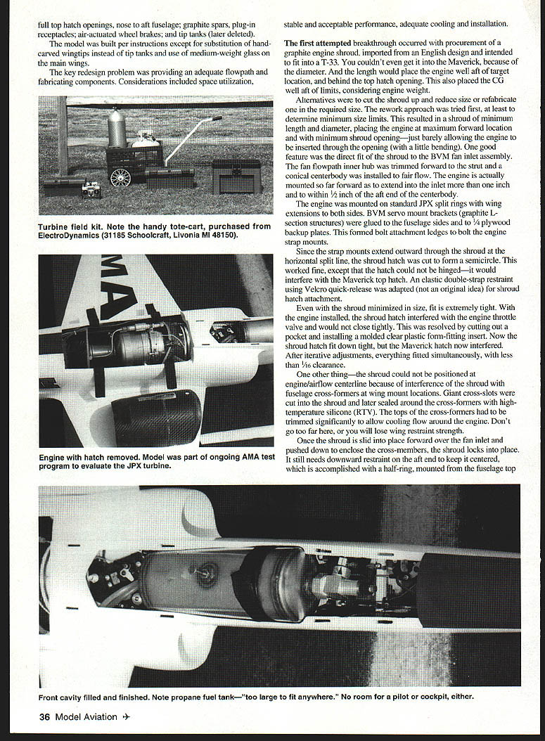
The next major obstacles were fuel- and oil-tank placement. There were no good options. The oil tank needs to be positioned in the bottom of the fuselage. If it is located higher, oil will siphon into the engine after shutdown. The fuel tank was too large to fit anywhere. It was finally placed half-in/half-out of the forward fuselage. The other half extends into the forward canopy.
There is no room for a scale pilot and cockpit. Even so, the F1 forward former must be cut down to lower the tank sufficiently to close the canopy over it. Since almost none of the crossbrace part of the former remained, it was reinforced with graphite.
The oil tank is under the fuel tank, immediately in front of the inlet duct 'F'. Oil tap, engine compressor air tap, and retract/brake air reservoir connector are neatly mounted on a wooden plate over the oil tank, behind the fuel tank.
Radio, servos, and system packaging
If you are beginning to understand that things are getting even tighter, you are correct. We still needed room for seven servos in the fuselage (and four in the wing), two air reservoirs, brakes and retracts, nose gear, radio, and batteries.
There is room for two elevator servos in the traditional BVM location aft of the wing spar cross-members in the bottom of the fuselage. The switch for wheel brakes is operated by full down-elevator.
Unfortunately, the engine shroud takes up the location specified on the plans for the brake switch. An alternate location aft of the elevator servo had sufficient space, because of the taper in the shroud junction to the tailpipe.
The rudder servo fits per the original plan, just forward of the shroud. The foam-ram reverser just fit in the cavity on the other side. The nosegear steering servo is positioned under the fuel tank just aft of the F1 former, along the retracted nosegear.
The engine throttle servo mounts next to the plug-in mounting plate, which was partially cut away to make space, in the forward hatch top area. Its linkage is carefully fed through fuselage cavities from the forward compartment into the engine shroud. A short length of graphite arrowshaft is used, since very high servo loads would otherwise bend this linkage.
Battery and radio receiver are located in the nose and partitioned forward of the front hatch. This leaves the remainder of the forward hatch section in front of the F1 former and nosegear mount for the retract servo with air switch (for main gear) and the fuel tank emergency shutoff servo. Because of loads (this tank valve tends to freeze), a JR 472 high-capacity servo was utilized. The fuel tank valve had to be reworked to angle down into the fuselage cavity just right.
Radio leads, fuel lines and oil lines required careful programming of available remaining space. Space utilization exceeds 80%, from the engine shroud to the nose. Final installation is orderly, if unavoidably busy.
The end result of this high-density packaging was a total dry weight of 15½ pounds. It would have been higher but the forward engine location eliminated need for any nose balance weight. How's that for luck? The CG was right on the money!
Testing and flight performance
Initial testing showed outer fuselage temperatures remaining below 110°F, even with extended running at 100 percent power on the ground. Total fuel burn, including ground startup, was 6½ minutes, because only the smallest-available tank would fit in the fuselage.
The initial flight was conducted by Terry Nitsch. The outstanding flight characteristics of the Maverick were extended by the wonderful, endless power of the JPX turbine. The engine had been uprated to 14 pounds of takeoff thrust when converted to T250 configuration. Top speeds are unmentionably high. Smooth flying characteristics of the Maverick are fully retained, including slow, controllable landing characteristics.
Now that it is flying, it's easier to say that it's worth it. Given the alternative of current models expressly designed for turbines, it isn't a realistic choice. Now, if someone would kit these sport models with a little additional space for fuel ...
Delmar Ellis
Transcribed from original scans by AI. Minor OCR errors may remain.

