
Turning, Turning, Turning
by Frank Granelli
LAST MONTH I outlined the types of model engines, highlighting performance and design differences. But of all the available types, sizes, and variations of model engines, the most common kind used in trainers today is the two-stroke, .40-cubic-inch-displacement “Ol’ Reliable,” or “forty.”
In this installment I’ll cover this type of engine’s initial care and feeding, including mounting, break-in, and needle settings. Following this segment I’ll cover propellers, glow plugs, fuel, maintenance, and repair. Except for history and propeller sizes, everything I will discuss in these articles will apply to most two-stroke engines from .10 to 2.10 displacement.
The .40 two-stroke has been the most popular RC engine for several decades. A logical outgrowth of CL’s most popular engine of the 1950s—the Fox .35—the .40 RC offered increased displacement to compensate for the power that was lost when incorporating a throttle.
The first .40 was familiar to CL pilots who were transferring to RC; remained easy to hand start; was approximately the same physical size, weight, and power as the .35; and offered good fuel economy. These features made the .40 popular then and remain its key advantages to this day.
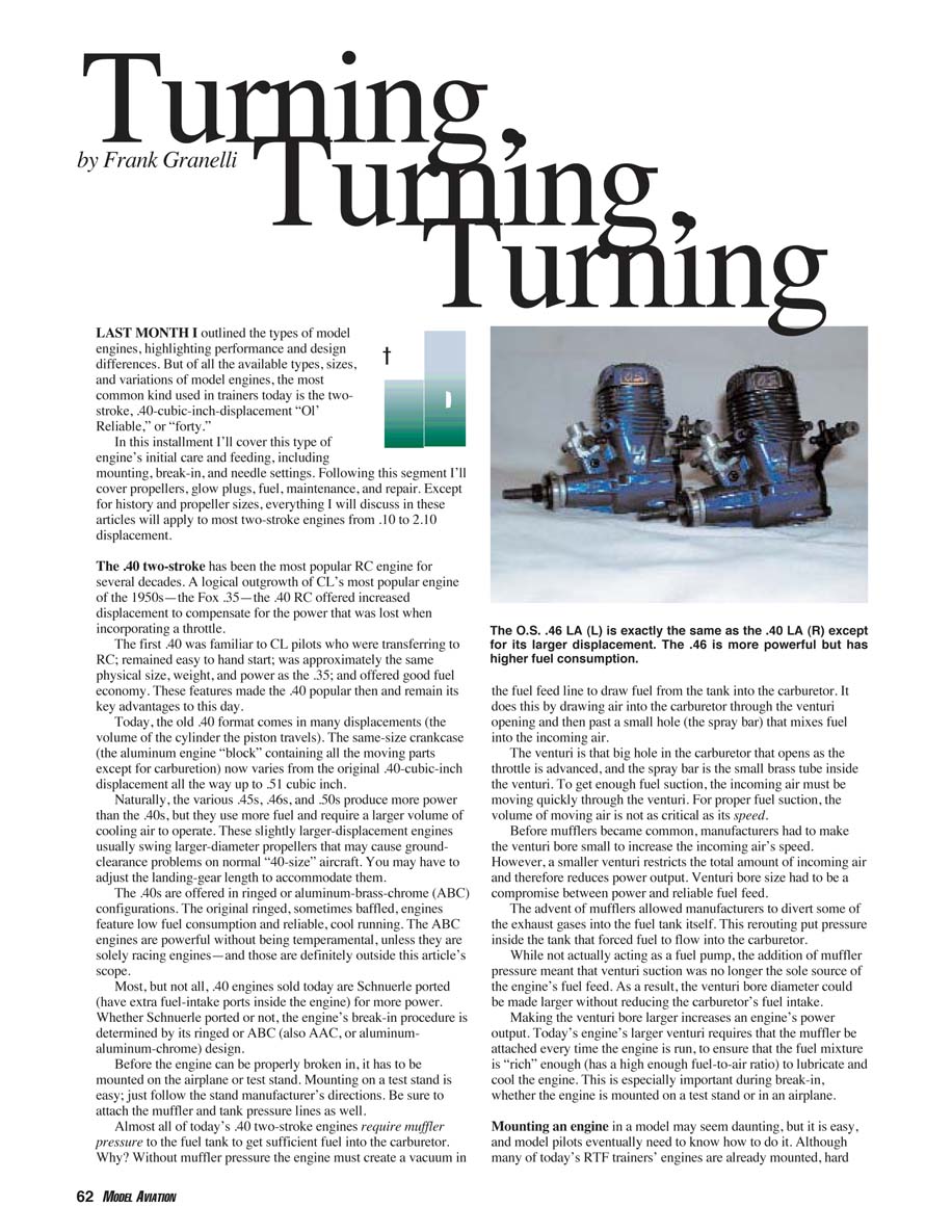
Today, the old .40 format comes in many displacements (the volume of the cylinder the piston travels). The same-size crankcase (the aluminum engine “block” containing all the moving parts except for carburetion) now varies from the original .40-cubic-inch displacement all the way up to .51 cubic inch.
Naturally, the various .45s, .46s, and .50s produce more power than the .40s, but they use more fuel and require a larger volume of cooling air to operate. These slightly larger-displacement engines usually swing larger-diameter propellers that may cause ground-clearance problems on normal “40-size” aircraft. You may have to adjust the landing-gear length to accommodate them.
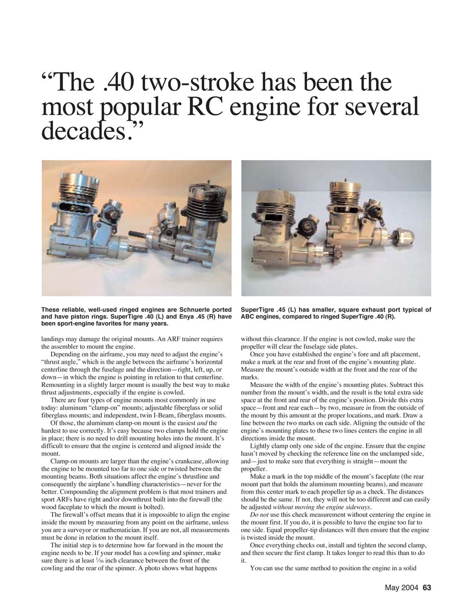
The .40s are offered in ringed or aluminum-brass-chrome (ABC) configurations. The original ringed, sometimes baffled, engines feature low fuel consumption and reliable, cool running. The ABC engines are powerful without being temperamental, unless they are solely racing engines—and those are definitely outside this article’s scope.
Most, but not all, .40 engines sold today are Schnuerle-ported (have extra fuel-intake ports inside the engine) for more power. Whether Schnuerle-ported or not, the engine’s break-in procedure is determined by its ringed or ABC (also AAC, or aluminum-aluminum-chrome) design.
Mounting and thrust angle
Before the engine can be properly broken in, it has to be mounted on the airplane or test stand. Mounting on a test stand is easy; just follow the stand manufacturer’s directions. Be sure to attach the muffler and tank pressure lines as well.
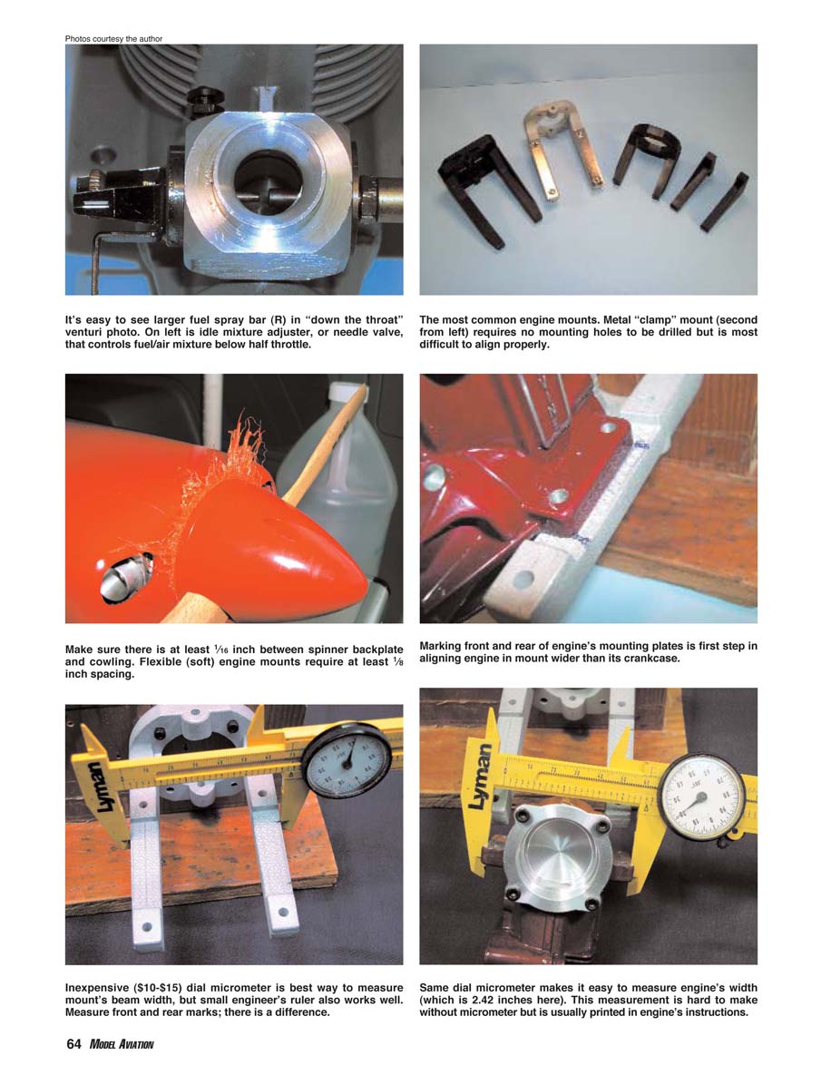
Almost all of today’s .40 two-stroke engines require muffler pressure to the fuel tank to get sufficient fuel into the carburetor. Why? Without muffler pressure the engine must create a vacuum in the fuel feed line to draw fuel from the tank into the carburetor. It does this by drawing air into the carburetor through the venturi opening and then past a small hole (the spray bar) that mixes fuel into the incoming air. The venturi is that big hole in the carburetor that opens as the throttle is advanced, and the spray bar is the small brass tube inside the venturi. To get enough fuel suction, the incoming air must be moving quickly through the venturi. For proper fuel suction, the volume of moving air is not as critical as its speed.
Before mufflers became common, manufacturers had to make the venturi bore small to increase the incoming air’s speed. However, a smaller venturi restricts the total amount of incoming air and therefore reduces power output. Venturi bore size had to be a compromise between power and reliable fuel feed. The advent of mufflers allowed manufacturers to divert some of the exhaust gases into the fuel tank itself. This rerouting put pressure inside the tank that forced fuel to flow into the carburetor. While not actually acting as a fuel pump, the addition of muffler pressure meant that venturi suction was no longer the sole source of the engine’s fuel feed. As a result, the venturi bore diameter could be made larger without reducing the carburetor’s fuel intake.
Making the venturi bore larger increases an engine’s power output. Today’s engines’ larger venturi requires that the muffler be attached every time the engine is run, to ensure that the fuel mixture is “rich” enough (has a high enough fuel-to-air ratio) to lubricate and cool the engine. This is especially important during break-in, whether the engine is mounted on a test stand or in an airplane.
Mounting an engine in a model may seem daunting, but it is easy, and model pilots eventually need to know how to do it. Although many of today’s RTF trainers’ engines are already mounted, hard landings may damage the original mounts. An ARF trainer requires the assembler to mount the engine.
Depending on the airframe, you may need to adjust the engine’s “thrust angle,” which is the angle between the airframe’s horizontal centerline through the fuselage and the direction—right, left, up, or down—in which the engine is pointing in relation to that centerline. Remounting in a slightly larger mount is usually the best way to make thrust adjustments, especially if the engine is cowled.
Common mount types
There are four types of engine mounts most commonly in use today:
- Aluminum clamp-on mounts
- Adjustable fiberglass mounts
- Solid fiberglass mounts
- Independent twin I-beam fiberglass mounts
Of those, the aluminum clamp-on mount is the easiest and the hardest to use correctly. It’s easy because two clamps hold the engine in place; there is no need to drill mounting holes into the mount. It’s difficult to ensure that the engine is centered and aligned inside the mount.
Clamp-on mounts are larger than the engine’s crankcase, allowing the engine to be mounted too far to one side or twisted between the mounting beams. Both situations affect the engine’s thrustline and consequently the airplane’s handling characteristics—never for the better. Compounding the alignment problem is that most trainers and sport ARFs have right and/or downthrust built into the firewall (the wood faceplate to which the mount is bolted).
The firewall’s offset means that it is impossible to align the engine inside the mount by measuring from any point on the airframe, unless you are a surveyor or mathematician. If you are not, all measurements must be done in relation to the mount itself.
Centering an engine in a clamp-on mount
- Determine how far forward in the mount the engine needs to be. If your model has a cowling and spinner, make sure there is at least 1/16 inch clearance between the front of the cowling and the rear of the spinner. If the engine is not cowled, make sure the propeller will clear the fuselage side plates.
- Make a mark at the rear and front of the engine’s mounting plate to establish fore-and-aft placement.
- Measure the mount’s outside width at the front and the rear of those marks.
- Measure the width of the engine’s mounting plates. Subtract this number from the mount’s width to get the total extra side space at the front and rear of the engine’s position.
- Divide that extra space (front and rear each) by two. Measure in from the outside of the mount by this amount at the proper locations and mark.
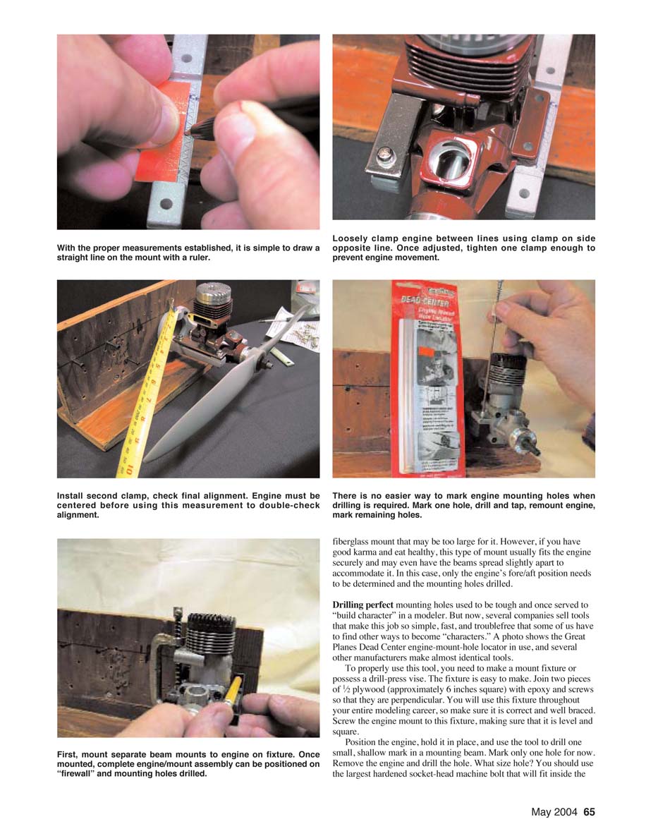
- Draw a line between the two marks on each side. Aligning the outside of the engine’s mounting plates to these two lines centers the engine in all directions inside the mount.
- Lightly clamp only one side of the engine. Ensure the engine hasn’t moved by checking the reference line on the unclamped side, and—just to make sure that everything is straight—mount the propeller.
- Make a mark in the top middle of the mount’s faceplate (the rear mount part that holds the aluminum mounting beams), and measure from this center mark to each propeller tip as a check. The distances should be the same. If not, adjust the engine fore/aft in the mount (do not assume equal prop-tip distances alone ensures correct centering).
- Once everything checks out, install and tighten the second clamp, then fully secure the first clamp.
You can use the same method to position the engine in a solid mount, but it is more difficult to make minor fore/aft adjustments when the mounting plate is one piece. The independent twin I-beam mount makes engine alignment the easiest because adjustments can be made to each beam independently.
Fiberglass mounts are sometimes slightly large for an engine. If the beams are spread slightly apart, the mount may fit securely; in that case only the engine’s fore/aft position needs to be determined and the mounting holes drilled.
Drilling perfect mounting holes
Drilling perfect mounting holes used to be tough, but now several companies sell tools that make this job simple, fast, and trouble-free. Tools such as the Great Planes Dead Center engine-mount-hole locator (and similar tools from other manufacturers) simplify the process.
To properly use such a tool you need to make a mount fixture or possess a drill-press vise. The fixture is easy to make: join two pieces of 1/2-inch plywood (approximately 6 inches square) with epoxy and screws so that they are perpendicular. Make sure it is correct and well braced. Screw the engine mount to this fixture, making sure that it is level and square.
Position the engine, hold it in place, and use the tool to drill one small, shallow mark in a mounting beam. Mark only one hole for now. Remove the engine and drill the hole.
What size hole? Use the largest hardened socket-head machine bolt that will fit inside the engine's mounting holes. The screws that came with your engine mount are okay, but hardened steel bolts are stronger and easier to install. Most .40 engines use 4-40 or 6-32 bolt sizes.
After you have drilled the hole, tap matching threads into it. Fiberglass is softer than metal, so use a drill that is one size smaller than what is printed on the tap. Use a No. 37 drill for 6-32 bolts and a No. 44 drill for 4-40 bolt holes. It is best to use a drill press and the fixture you made (or a drill-press vise) here. You can buy a good drill press for less than $40, and they are good investments; you will use one for many years in your modeling.
Do not use oil while tapping the threads; the fiberglass contains enough carbon to lubricate the tap. Some oils can weaken the mount material, causing the threads to break or "strip out."
Using the hole you drilled and tapped, remount the engine, check to make sure everything is still positioned correctly, and then mark the remaining three holes. It is best to drill and tap one hole at a time, remount, and then mark the next hole. This is not essential, but it can prevent cumulative errors because each hole may be drilled slightly off center.
You use the same mounting procedure with the other mount types. For independent I-beam mounts, attach one I-beam to your fixture, ensure that it is square, clamp the engine to it, and attach the other I-beam to the fixture. Then drill and tap the holes as described. When you are using adjustable fiberglass mounts, slide them together per the instructions, attach to the fixture, and drill and tap.
With the engine properly and securely mounted on the airplane, you are ready to start the break-in procedure. Well, not just yet. You'll need fuel, the right propeller, a glow plug, a glow-plug igniter, and a starter—electric or hand. Glow-plug igniters and starters will come later, as will detailed glow-plug and fuel selections. For now, assume that you have the best of each.
Break-in overview
Break-in propellers are important. The size of propeller used during break-in depends on the engine type—ringed or ABC (AAC).
- For ringed engines, use a propeller that is an inch less in diameter than will be used in flight.
- ABC engines need the same propeller as will normally be flown.
The propeller's construction—wood, fiberglass, etc.—should match for ABC engines but is noncritical for ringed engines.
ABC engines should be broken in exactly as they will be flown, except for the high-speed mixture setting. In an ABC type, the cylinder's bore (diameter) tapers from a larger diameter at the bottom to a smaller diameter at the top. The piston has a constant diameter that is almost equal to the cylinder's diameter at its bottom.
As the piston travels upward, the bore becomes smaller until, at the top of its stroke, the piston is slightly larger than the cylinder's diameter. However, the piston and cylinder react to the heat generated when the engine runs by expanding differently; the cylinder expands more than the piston.
Since the piston is larger than the cylinder at the top in an ABC engine, break-in involves the cylinder’s wearing away to become an exact fit to the piston when both parts are hot. But most ABC engines are built with the cylinder slightly too tight. Therefore, when the engine is first run and heats up, the cylinder remains too small. During the break-in, the cylinder loses material until it fits the piston exactly when hot.
How much wear occurs depends on the engine's rpm and propeller load. Using the same propeller for break-in and normal running ensures that the initial wear pattern will match the run pattern. The only difference is that the engine will be run slightly richer than normal during break-in for extra cooling and lubrication. ABC engines normally have short break-in periods averaging five to 10 flights.
Ringed engines do not need to turn the same rpm during break-in as during flight, but they do need to run cooler than normal. Thus ringed engines require a richer fuel mixture during initial flights. Using a propeller that is an inch less in diameter reduces the engine load and heat generated, while allowing the engine to achieve enough rpm for break-in on the ground with a rich mixture. Ringed engines usually require more break-in time, averaging 15–20 flights.
Safety first
Before running any engine, use common sense and take every precaution:
- The airplane must be immobile.
- The propeller must be tight.
- Clear all obstacles.
- Do not smoke.
- Do it outside.
- Wear eye and ear protection.
- Never stand to the side in the propeller arc or make adjustments from in front of the engine.
- Do not reach around a spinning propeller to make needle-valve adjustments, remove the glow driver, or for any other purpose.
Make all adjustments while standing behind the engine. I have taken far too many friends to hospitals through the years, watched too many microsurgeries, and hoped far too many times that they could reattach nearly severed fingers not to warn anyone reading this to be careful. There is no reset button once that propeller hits you. This goes for any type of propeller turned by any type of engine or motor.
Break-in procedure for ringed engines
Break-in procedures for ringed engines vary by individuals, but consider the following:
- Open the high-speed needle valve a half turn more than the engine directions state.
- Have the throttle wide open and the model properly secured.
- Prime the engine by holding one finger over the venturi, hold the propeller securely, and rotate it counterclockwise until fuel moves through the fuel line and nearly into the carburetor. Do not have the glow driver attached.
- Connect the glow driver, making sure any wire is clear of the propeller arc, and start the engine. Remove the glow driver.
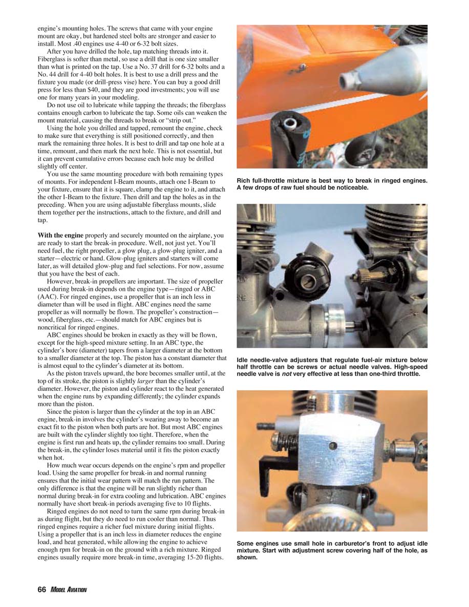
- The engine will run at full throttle, but extremely rich. If the engine falters, close the needle valve (while standing behind the engine) just enough to ensure a steady run. The engine should be spitting raw, unburnt fuel from the muffler and running roughly 2,000 rpm slower than normal. Run the engine this way for five minutes, then shut it down and let it cool.
- Repeat this procedure twice more. On the third run, let the engine run rich for two minutes, then "lean" the mixture: turn the needle valve clockwise until the engine sound changes from a low-pitched tone to an alternating low-pitched/high-pitched sound. Stop there and let it run for 30 seconds, return to the rich setting for two minutes, then stop and let it cool.
- Restart and then lean the mixture to achieve that alternating sound, and let it run there for one minute. Richen the mixture again (open the needle valve), but only to a half turn less than the initial rich setting. Now the engine speed should be approximately 1,500 rpm lower than normal.
- After one minute of rich running, lean to the alternating-sound point and run for one minute. Continue alternating the needle-valve settings for five more minutes. Stop and let the engine cool.
- Restart and set the needle valve to the alternating-sound point. Run the engine at this point for three to five minutes.
If the engine holds rpm and doesn't seem to slow down, it is ready to finish the break-in while flying. Install the flying propeller. Total ground time is usually about 30 minutes.
Idle adjustment (initial)
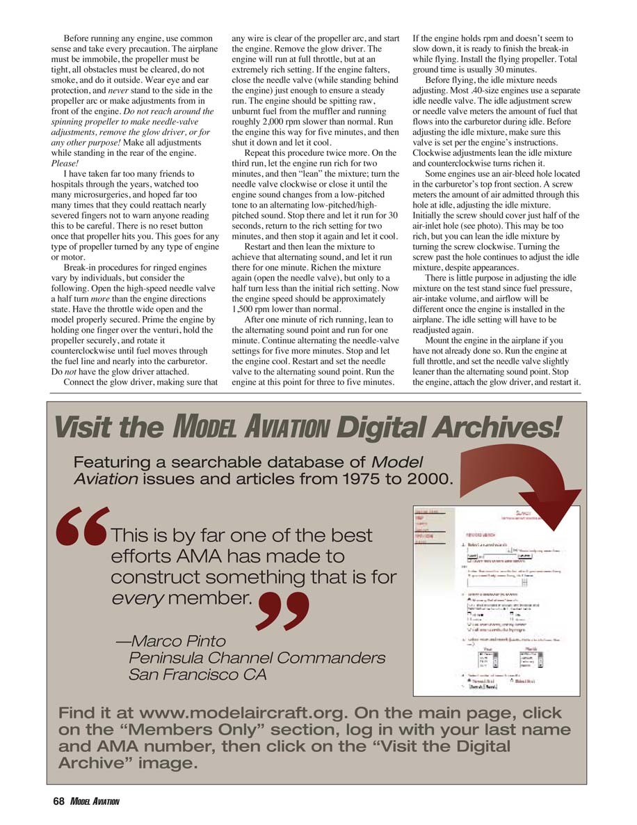
Before flying, the idle mixture needs adjusting. Most .40-size engines use a separate idle needle valve. The idle adjustment screw or needle valve meters the amount of fuel that flows into the carburetor during idle. Before adjusting the idle mixture, make sure the valve is set per the engine's instructions. Clockwise adjustments lean the idle mixture and counterclockwise turns richen it.
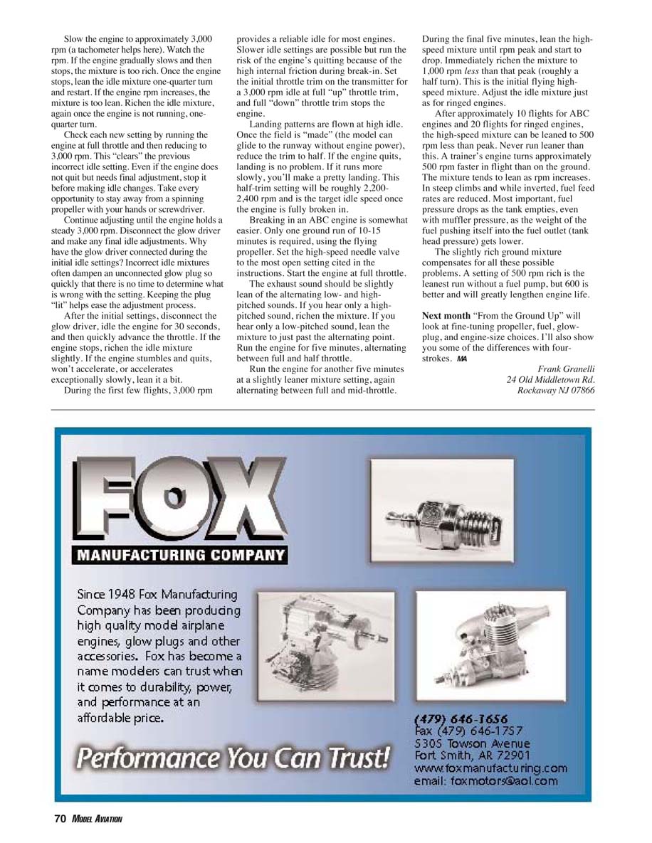
Some engines use an air-bleed hole located in the carburetor's top-front section. A screw meters the amount of air admitted through this hole at idle, adjusting the idle mixture. Initially the screw should cover just half of the air-inlet hole. This may be too rich, but you can lean the idle mixture by turning the screw clockwise. Turning the screw past the hole continues to adjust the idle mixture, despite appearances.
There is little purpose in adjusting the idle mixture on the test stand since fuel pressure, air-intake volume, and airflow will be different once the engine is installed in the airplane. The idle setting will have to be readjusted again.
Mount the engine in the airplane if you have not already done so. Run the engine at full throttle, and set the high-speed needle valve slightly leaner than the alternating-sound point. Stop the engine, attach the glow driver, and restart it.
Slow the engine to approximately 3,000 rpm (a tachometer helps here). Watch the rpm:
- If the engine gradually slows and then stops, the mixture is too rich. Once the engine stops, lean the idle mixture one-quarter turn and restart. If the engine rpm increases, the mixture is too lean. Richen the idle mixture one-quarter turn.
- Check each new setting by running the engine at full throttle and then reducing to 3,000 rpm. This "clears" the previous incorrect idle setting.
- Even if the engine does not quit but needs final adjustment, stop it before making idle changes.
Continue adjusting until the engine holds a steady 3,000 rpm. Disconnect the glow driver and make any final idle adjustments. Why have the glow driver connected during the initial idle settings? Incorrect idle mixtures often dampen an unconnected glow plug so quickly that there is no time to determine what is wrong with the setting. Keeping the plug "lit" helps ease the adjustment process.
After the initial settings, disconnect the glow driver, idle the engine for 30 seconds, and then quickly advance the throttle. If the engine stops, richen the idle mixture slightly. If the engine stumbles and quits, won't accelerate, or accelerates exceptionally slowly, lean it a bit.
During the first few flights, 3,000 rpm provides a reliable idle for most engines. Slower idle settings are possible but run the risk of the engine quitting because of the high internal friction during break-in. Set the initial throttle trim on the transmitter for a 3,000 rpm idle at full "up" throttle trim, and full "down" throttle trim stops the engine.
Landing patterns are flown at high idle. Once the field is "made" (the model can glide to the runway without engine power), reduce the trim to half. If the engine quits, landing is no problem. If it runs more slowly, you'll make a pretty landing. This half-trim setting will be roughly 2,200–2,400 rpm and is the target idle speed once the engine is fully broken in.
Break-in procedure for ABC engines
Breaking in an ABC engine is somewhat easier. Only one ground run of 10–15 minutes is required, using the flying propeller. Set the high-speed needle valve to the most open setting cited in the instructions. Start the engine at full throttle.
The exhaust sound should be slightly lean of the alternating low- and high-pitched sounds. If you hear only a high-pitched sound, richen the mixture. If you hear only a low-pitched sound, lean the mixture to just past the alternating point. Run the engine for five minutes, alternating between full and half throttle.
Run the engine for another five minutes at a slightly leaner mixture setting, again alternating between full and mid-throttle.
During the final five minutes, lean the high-speed mixture until rpm peaks and starts to drop. Immediately richen the mixture to 1,000 rpm less than that peak (roughly a half turn). This is the initial flying mixture. Adjust the idle mixture just as for ringed engines.
After approximately 10 flights for ABC engines and 20 flights for ringed engines, the high-speed mixture can be leaned to 500 rpm less than peak. Never run leaner than this. A trainer's engine turns approximately 500 rpm faster in flight than on the ground. The mixture tends to lean as rpm increases. In steep climbs and while inverted, fuel flow rates are reduced. Most important, fuel pressure drops as the tank empties, even without muffler pressure, as the weight of the fuel pushing itself into the fuel outlet (tank head pressure) gets lower.
The slightly rich ground mixture compensates for all these possible problems. A setting of 500 rpm rich is the leanest run without a fuel pump, but 600 rpm rich is better and will greatly lengthen engine life.
Closing
Next month "From the Ground Up" will look at fine-tuning propeller, fuel, glow-plug, and engine-size choices. I'll also show you some of the differences with four-strokes.
MA
Frank Granelli 24 Old Middletown Rd. Rockaway, NJ 07866
Transcribed from original scans by AI. Minor OCR errors may remain.

