
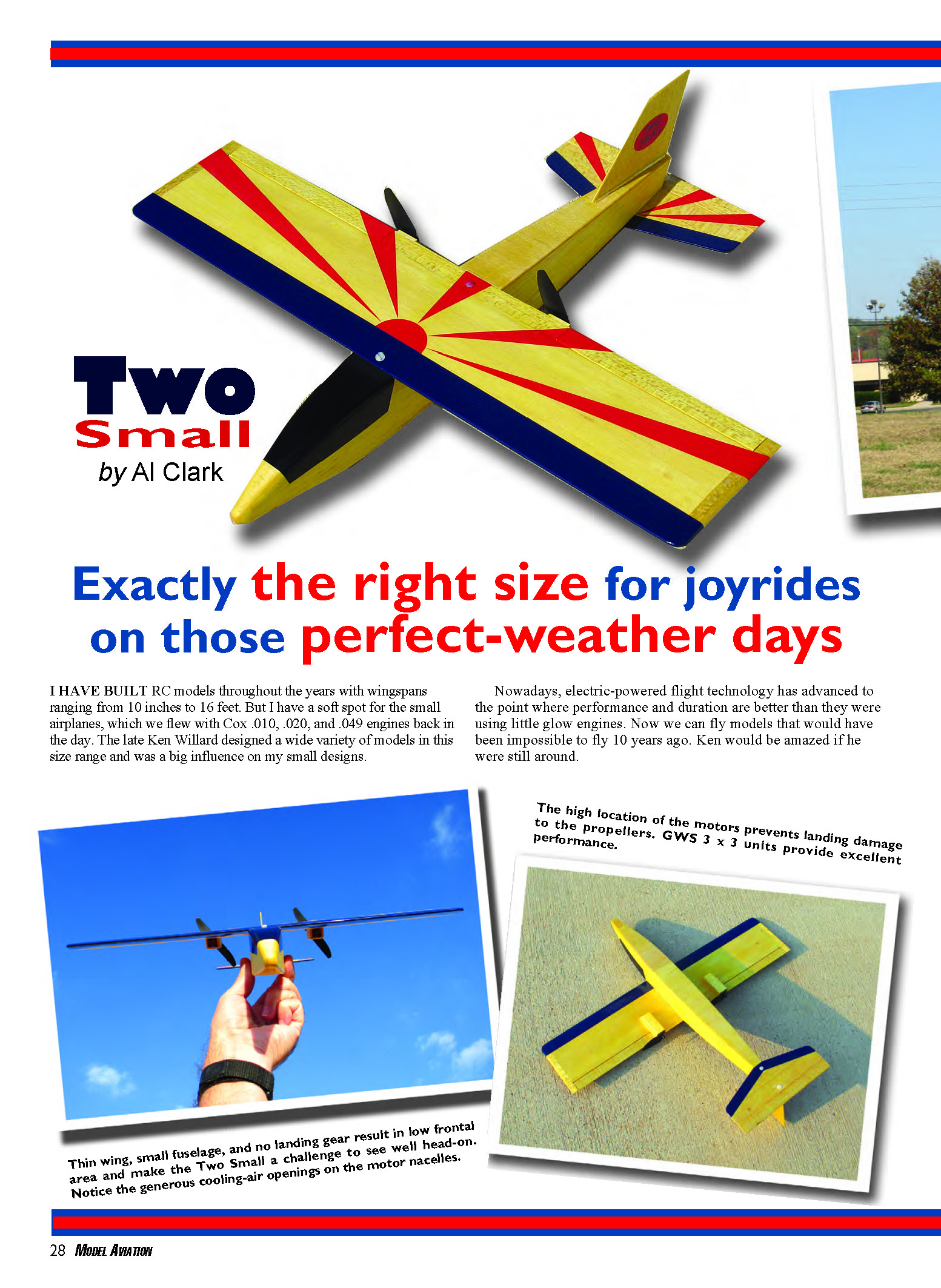
Two Small
I have built RC models throughout the years with wingspans ranging from 10 inches to 16 feet. But I have a soft spot for the small airplanes, which we flew with Cox .010, .020, and .049 engines back in the day. The late Ken Willard designed a wide variety of models in this size range and was a big influence on my small designs.
Nowadays, electric-powered flight technology has advanced to the point where performance and duration are better than they were using little glow engines. Now we can fly models that would have been impossible to fly 10 years ago. Ken would be amazed if he were still around.
The Box
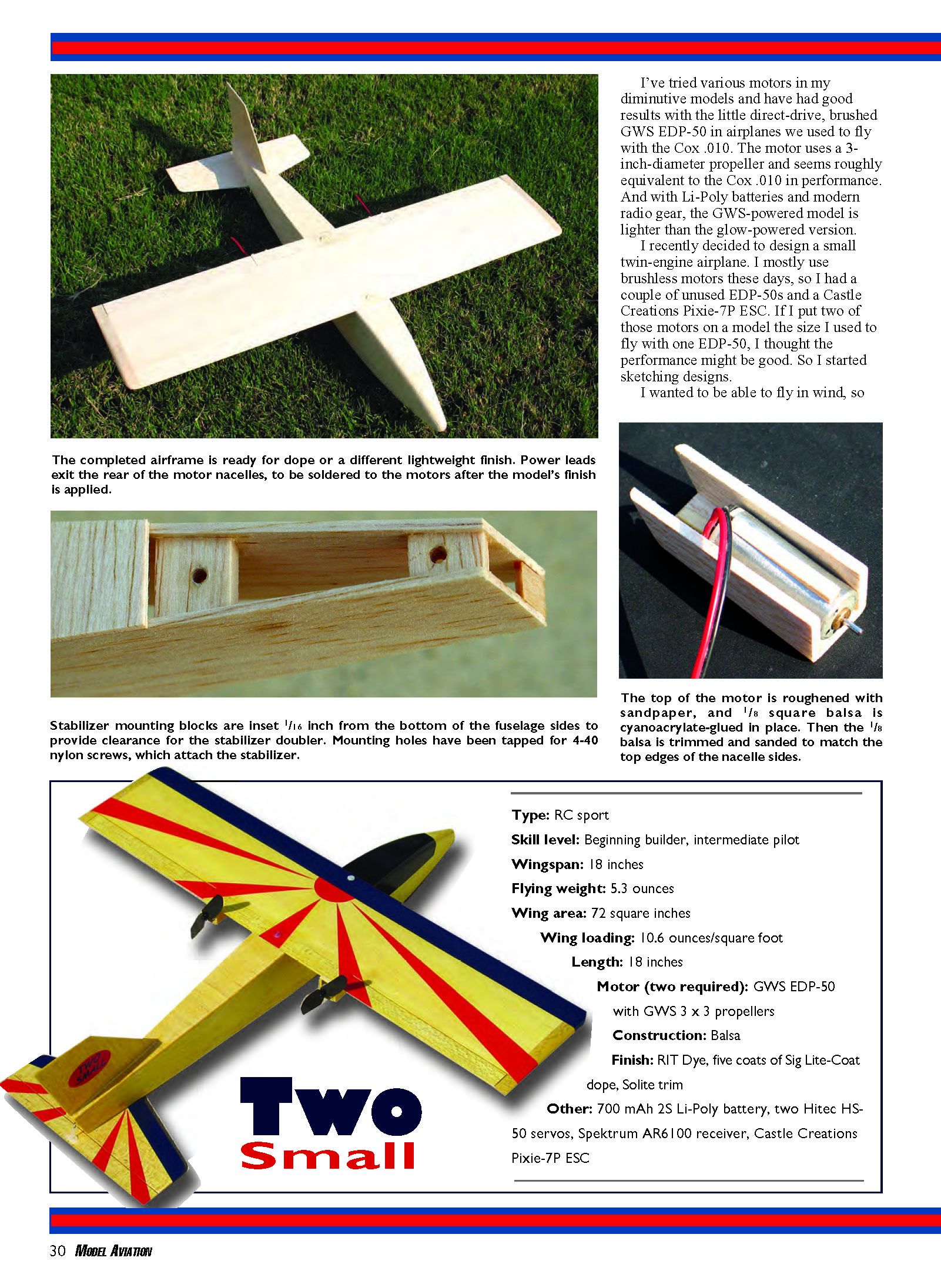
The simple carrying box is made from 1/4 luan plywood. Three small hinges and two overcenter latches hold it together. Finished with polyurethane, it's outfitted inside with bubble pack and Velcro straps. There is a handle on the top of the lid.
For those of you who ride motorcycles, as I do, I'll tell you how to make the carrying box I constructed for the Two Small. I obtained a 2 x 4-foot sheet of 1/4 (actually 5.2 mm thick) luan plywood at The Home Depot, small brass hinges, and a couple of overcenter latches. I sized the case around my Spektrum DX7 transmitter and the model's wingspan.
The exterior dimensions are 18.63 x 8.25 x 6.5 inches. The parting line between the top and bottom is 3.75 inches up from the bottom.
I used a Skil saw to cut the side pieces first, keeping their grain matched with pencil-mark identifications, and the top and bottom pieces last. I cleaned up the edges with a sanding block.
The pieces were attached using Titebond and small brass brads spaced 4–5 inches apart. I drilled 3/64-inch-diameter holes everywhere I put a brad so the wood wouldn't split.
I brushed two coats of water-based polyurethane on the inside and three coats on the outside. I installed the hinges and latches after varnishing and trimmed off the screws inside the box with my Dremel carbide wheel.
The transmitter, batteries, tools, and stabilizer go in the bottom, and the wing and fuselage go in the top. I used Velcro sticky-back pads and Velcro straps along with bubble pack to hold everything in place. After loading the box, I determined where the balance point was and installed the carrying handle at that location.
The case works well. Even if you don't have a motorcycle, it's nice to be able to throw it in the car and not have to worry about damage.
—Al Clark
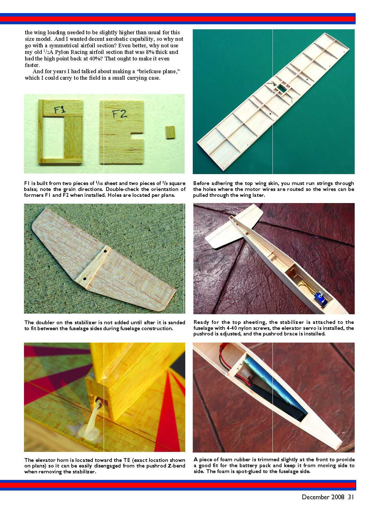
The author is heading out on another motorcycle trip with the Two Small in its carrying box, along for the ride and ready to fly at a moment's notice. This model design allows the author to combine his two favorite hobbies.
I've tried various motors in my diminutive models and have had good results with the little direct-drive, brushed GWS EDP-50 in airplanes we used to fly with the Cox .010. The motor uses a 3-inch-diameter propeller and seems roughly equivalent to the Cox .010 in performance. And with Li-Poly batteries and modern radio gear, the GWS-powered model is lighter than the glow-powered version.
I recently decided to design a small twin-engine airplane. I mostly use brushless motors these days, so I had a couple of unused EDP-50s and a Castle Creations Pixie-7P ESC. If I put two of those motors on a model the size I used to fly with one EDP-50, I thought the performance might be good. So I started sketching designs.
I wanted to be able to fly in wind, so the wing loading needed to be slightly higher than usual for this size model. And I wanted decent aerobatic capability, so why not go with a symmetrical airfoil section?
Type and Specifications
- Type: RC sport
- Skill level: Beginning builder, intermediate pilot
- Wingspan: 18 inches
- Flying weight: 5.3 ounces
- Wing area: 72 square inches
- Wing loading: 10.6 ounces/square foot
- Length: 18 inches
- Motor (two required): GWS EDP-50 with GWS 3 x 3 propellers
- Construction: Balsa
- Finish: RIT Dye, five coats of Sig Lite-Coat dope, Solite trim
- Other: 700 mAh 2S Li-Poly battery, two Hitec HS-50 servos, Spektrum AR6100 receiver, Castle Creations Pixie-7P ESC
Even better, why not use my old 1/2A Pylon Racing airfoil section that was 8% thick and had the high point back at 40%? That ought to make it even faster.
And for years I had talked about making a "briefcase plane," which I could carry to the field in a small carrying case. However, I had never gotten around to doing it. This model would be the perfect candidate.
After a few evenings with the calculator and a fair amount of head scratching, I created the Two Small. It fits in a small box with the transmitter, batteries, and a few tools, and it combines my favorite pastimes: flying models and riding motorcycles. The airplane's box bungees easily onto my motorcycle's passenger seat, and I am ready to fly anywhere I find a grass field.
Two Small is controlled with aileron, elevator, and throttle. It performs excellently, and the symmetrical airfoil allows good inverted flight and outside loops in addition to the usual aileron and elevator aerobatics. Flight duration is 11 minutes at full throttle. I put the propellers at the wing TE so they would make just enough noise to get that cool twin-engine sound.
You probably have enough material in your scrap box to build a Two Small, so grab some wood and let's get started!
Construction
Make the wing skins from contest balsa. If you cannot find it, medium-density balsa will work; it will just be slightly heavier. Do all gluing with thin cyanoacrylate unless otherwise specified.
Tail
Cut the tail parts from 1/16 medium-density, C-grain sheet balsa. Mark the elevator hinge positions and carefully cut the slots into the stabilizer and elevator with a #11 hobby-knife blade. Temporarily hinge the elevator (no glue) and round all the stabilizer's outer edges. Use 1/8 x 3/8 pieces of Sig Easy Hinge material for all hinges.
Round the fin's outer edges except for the root. Drill the 1/16-inch-diameter hole in the elevator for the control horn. The hole offsets allow the stabilizer assembly to be removed easily from the fuselage. You will cut the 1/16 stabilizer doubler later, during fuselage construction. Final-sand with 220-grit paper. The hinges and horn are installed after doping.
Wing
Ken Willard liked to use fully sheeted wings on some designs. I have done so on many of my models and on Two Small. Fully sheeted wings are quick to build, strong, and require no covering.
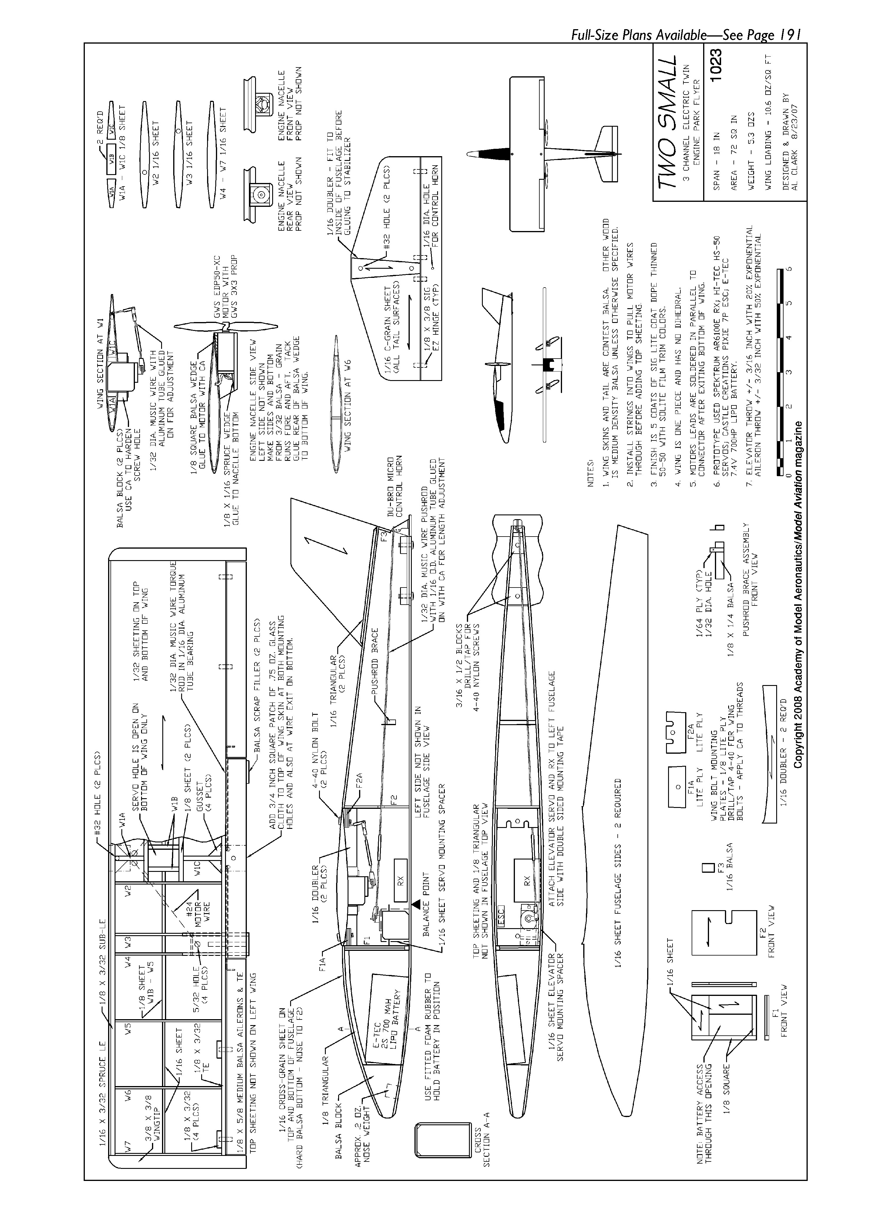
Before beginning wing construction, use a pencil or pen to extend the rib lines out past the LE and TE on the plans. This will help you position the ribs on top of the lower wing skin. Note the position of the wing-spar pieces.
I used 4-inch-wide sheet for the wing skins, but you will probably need to edge-join 3-inch sheets. I recommend Ambroid or Sigment glue for this, to avoid warping.
Cut the lower and upper wing skins to size, leaving a bit of extra width at the LE to allow for the rib curvature. Pin a piece of 1/8 square balsa a couple inches longer than the wingspan to the plans at the LE and TE, under the lower skin, to act as shims so that the skin will conform to the ribs.
Sand the correct angle on the TE bottom, and glue it to the lower wing skin. (I used 1/8 square balsa for the sub-LE and TE pieces and trimmed/sanded them before gluing on the top skin.) Correctly position the lower skin over the plans. You can use pins to hold the position if you don't mind holes in the skin, or hold the skin in position while gluing in the ribs.
Drill the 5/32-inch-diameter angled holes in ribs W2 and W3 in the positions shown on the plans. Glue ribs W2–W7 to the lower wing skin. Make sure there are no gaps between the ribs and skin; adjust the shims if necessary.
Pay particular attention to ensure the proper position of ribs W3 and W4. Make sure ribs W7 are perpendicular, since the wingtips attach to them.
Sand the correct angle on the bottom of the sub-LE, and glue it to the lower skin. Align it with a straightedge before gluing.
Glue ribs W1A–W1C and the 1/8 crosspieces between the two W2 ribs and the LE and TE. Before gluing the forward 1/8 crosspiece, drill the 5/32-inch-diameter angled holes per the plans. Glue in the four gussets on W1A and W1C at the LE and TE.
Glue all spar pieces in place. Notice that they are 1/8 inch thick out to rib W5 and 1/16 inch thick between W5 and W7. The grain runs spanwise.
Add the four aileron-hinge reinforcing pieces to the TE. Drill four 5/32-inch-diameter holes through the lower skin as the plans show. These are exit holes for the motor wires. A sharpened brass tube works well for this. Cut out the lower skin between ribs W1B and the front and rear crosspieces; this is where the aileron servo will mount.
Carefully sand the top of the sub-LE and TE to the correct angle, flush with the ribs' tops. It helps to protect the tops of the ribs with a strip of tape until sanding is completed. Carefully sand the tops of the spar pieces, gussets, and aileron-hinge reinforcing pieces flush with the tops of the ribs. Again, you may want to protect the ribs with tape.
Before gluing on the top wing skin, run strings through the holes where the motor wires are routed so that the motor wires can be pulled through the wing later. I used kite string and left a few inches hanging out of each hole; I taped the excess to the lower wing skin to keep it out of the way.
You are ready to attach the top wing skin. Make sure the 1/8-inch-square shims are correctly positioned below the lower wing skin, and use pins angled through the W7 ribs to hold the wing structure in position. Ensure that there is no twist in the wing.
Apply Titebond to the tops of all ribs except the two W7s, to the spar pieces, and to the two 1/8-inch crosspieces at rib W1. Align the top wing skin, and glue along the TE with cyanoacrylate.
Use cyanoacrylate to tack the top wing skin to the sub-LE at each rib position, starting at W1 and alternating between the left and right sides as you work your way to the wingtips. Check the wing to ensure that it has no twist as you work out to the wingtips.
Make sure that the skin is contacting each rib before you tack it at the sub-LE, but don't pull excessively or it will become distorted. Once the skin is tacked at all the ribs, unpin the assembly from the building board, cyanoacrylate-glue the skin to the two W7 ribs, and finish gluing the skin to the sub-LE.
Trim the skins flush at the front of the wing and the TE if necessary. Glue on the 1/16 spruce LE. You can substitute basswood if you like. Sand the LE and skins flush with the W7 ribs. Shape the LE per the plans. This completes the basic wing assembly.
Make the two aileron torque-rod assemblies using 1/32-inch-diameter music wire and 1/16-inch-outside-diameter (OD) aluminum tube. The "horn" portion of the torque rod is angled aft. This prevents reverse differential in the ailerons, so it's important that you get the angle correct.
Flatten the end of a short piece of 1/16-inch-OD aluminum tubing, drill a 1/32-inch-diameter hole into the flattened portion, and glue it onto the "horn" portion of each torque rod. J.B. Weld adhesive is preferred.
Cut a 5/8-inch-wide piece of 1/8 medium to medium-hard balsa to use as the wing ailerons and center TE. Make this piece full span; it will be separated after shaping. Sand to the shape the plans show. The thickness at the front is slightly less than 1/8 inch, so make sure it fits flush with the top and bottom wing skins. When the shaping is complete, cut it into three pieces for the ailerons and center TE.
Mark the hinge positions and carefully cut the slots with a #11 hobby-knife blade. Bevel the ailerons' front edges. Drill a 1/32-inch-diameter hole into each aileron for the torque rod and carefully cut the 1/32-inch-wide slot into the front of each aileron for the torque rod to fit into.
Cut/file small notches into the wing aft edge and the front of the center TE piece, to provide clearance for the aileron torque-rod movement. Carefully cut 1/16-inch-wide slots into the front of the center TE piece to receive the torque-rod assemblies. Make sure the assemblies fit into the slots flush with the front edge. When satisfied with the fit, glue into place with five-minute epoxy or cyanoacrylate.
Check the fit of the center TE piece, with the torque rods installed, to the back of the wing. Make sure it is flush, top and bottom, and symmetrical. You don't want this piece to end up being a fixed wing flap. When satisfied with the fit, glue it to the wing's aft edge.
Temporarily hinge the ailerons to the wing (no glue) with a small gap to allow good movement. I use pieces of .015-inch-thick poster board for spacers. Tape the root end of the ailerons to the center TE piece. Glue the 3/8-inch-square wingtip blocks in place, cut/sand to shape, then remove the ailerons.
Use an EDP-50 as a spacer to correctly position the sides of each engine nacelle. Glue the sides to the bottom piece. Use a sanding block to round the bottom and outer front edges. Rough up the top of each motor case with sandpaper. (The top is determined by the motor leads and capacitor’s orientation; see nacelle front view on plans.) Glue a piece of 1/8 square balsa in place.
Put each EDP-50 in its nacelle with the motor’s back flush with the back edges of the sides and the 1/8 balsa at the top. Trim/sand the 1/8 square balsa until the shape matches the sides of the nacelle.
Make a small wedge from 1/16 x 1/8 spruce (basswood or plywood can be used instead), and glue to the bottom of each nacelle in front of the motor so that the motor’s aft end is flush with the rear of the nacelle. This positions the motor fore and aft and takes thrust loads. You might have to bend the capacitor on the front of the motor upward a bit to clear the wedge.
Position the left nacelle on the wing bottom. Make sure it is located per the plans and that there is no left or right thrust. The nacelle’s aft edge extends aft of the wing TE slightly more than 1/16 inch to provide propeller clearance. When satisfied that the position is correct, glue the nacelle to the wing. Repeat for the right nacelle. Glue a small scrap of balsa on the wing TE at the top of each nacelle’s aft end, and sand to fair it into the wing TE.
Make two balsa blocks to serve as the aileron servo mount. See plans for size and location. Glue the blocks to the wing bottom, install the servo, and mark and drill the two holes for the servo mounting screws. I use a 3/64-inch drill bit. Install the mounting screws, remove them, and harden the holes with a bit of cyanoacrylate.
Sand the wing with 220-grit paper. Add the two 3/4-inch-square reinforcing patches of thin glass cloth (Goldberg Nylon Tape will also work) to the wing at the front and back where the mounting screws will be. Sand these lightly to smooth. Holes for the wing-mounting screws will be drilled later.
Fuselage
Mark lines on the inside of each fuselage side at the aft end of the nose block and at formers F1 and F2. Build up F1 as plans show. Adhere the 1/16-inch wing-saddle doublers to the fuselage sides and the 1/16-inch elevator-servo mounting spacer to the left fuselage side. Glue the 1/8-inch triangular pieces to the top edge of the fuselage sides between the aft end of the nose block and the front edge of F1.
Glue the nose block to the right fuselage side. Carefully position the left fuselage side and glue to the nose block. Make sure the bottom edges are parallel and the fore and aft position is correct before adhering the left side.
Draw a straight line that is a bit longer than the fuselage sides on your building surface. Mark a centerline at the bottom of the nose block and formers F1 and F2. Place F1 and F2 between the fuselage sides and tape the aft ends of the sides to F3; make sure F1 is oriented correctly, with the battery opening on the right side. F3 should be flush with the top of the fuselage sides.
Lay the assembly over the line you drew on the building board, and make any adjustments so that the nose and all formers are centered over the line. When satisfied, glue all three formers to the fuselage sides.
Do not yet remove the tape from the sides at F3. Make the two stabilizer mounting blocks from medium balsa and glue between the fuselage sides, making sure they are spaced upward 1/16 inch from the bottom of the fuselage sides. Remove the tape from the sides at F3.
Sheet the fuselage bottom from the nose back to the front of the stabilizer with 1/16 cross-grain balsa. Cut the 1/16-inch-thick stabilizer doubler so that it is a good fit between the fuselage sides. Place the doubler between the fuselage sides, put a couple of tiny drops of five-minute epoxy on the stabilizer doubler, position the stabilizer on the glue line, and make sure the stabilizer is straight and the tips are centered with respect to the fuselage sides. When satisfied, glue the stabilizer in place.
Make sure the stabilizer is square with the centerline, and allow the epoxy to cure. Remove the stabilizer and finish adhering the doubler to the stabilizer with cyanoacrylate.
Place the stabilizer on the fuselage and drill two #43 holes through the stabilizer into the mounting blocks as shown on the plans. With the stabilizer still in place, tap both holes with a 4-40 tap. Remove the stabilizer and harden the tapped holes with a bit of cyanoacrylate.
When dry, run the tap through the threaded holes again to clean them up. Use a #32 drill to enlarge the holes in the stabilizer, and harden these holes and the area a small distance around them with cyanoacrylate. Trim two 4-40 nylon screws to the proper length to use for attaching the stabilizer.
Put a thin coating of five-minute epoxy on the elevator-servo mounting spacer and let cure; it gives a better grip for the servo tape. Install the elevator servo to the left fuselage side with 1/16-inch-thick double-stick mounting tape.
Make the elevator pushrod brace from a small piece of 1/64 (or 1/32) plywood and a piece of 1/8 x 1/4 balsa, as the plans show. Ensure that the 1/32-inch-diameter hole has a bit of play so the pushrod can slide freely. Make the 1/32-inch-diameter music-wire elevator-pushrod assembly per the plans with a Z-bend on the aft piece and an L bend on the front piece for the Du-Bro Micro E/Z Link. A 1/16-inch-OD aluminum tube coupler allows final adjustment.
Rough the ends of the pushrod pieces where they join at the coupler. Attach the front pushrod to the servo with the E/Z Link, slide the pushrod brace assembly onto the aft pushrod, and slide the aft pushrod into the aluminum tube coupler. Do not glue the coupler yet.
Trim the Du-Bro Micro Control Horn center post to length and glue the horn to the elevator using the previously drilled 1/16-inch-diameter hole. Temporarily hinge the elevator to the stabilizer (no glue), slide the outer hole of the control horn over the elevator-pushrod Z-bend, and mount the stabilizer to the fuselage.
Hook up the elevator servo and move the pushrod brace into position between the fuselage sides so that the pushrod makes a straight run from servo to control horn. Make sure the fuselage sides are not being pushed out of square by the pushrod brace. When satisfied, glue the pushrod brace to the fuselage sides.
Double-check for neutral elevator and then cyanoacrylate-glue the aluminum tube coupler to the pushrod pieces. This completes the elevator control installation, and you can remove the stabilizer from the fuselage.
Cut foam rubber to shape to use as a spacer in the front of the fuselage on the left side of the 2S 700 mAh Li-Poly battery; it should allow a snug fit. Sheet the top front and rear of the fuselage with 1/16 cross-grain balsa. Install the 1/8 light-plywood F1A and F2A wing mounting plates. Make sure the slots are cut/filed into F2A to allow aileron torque-rod movement.
Shape the front top of the fuselage per the plans and round the rest of the edges. Final-sand with 220-grit paper.
Make the 1/16 triangular balsa pieces to be mounted on the fin’s base. To do this easily, sand a 45° bevel on the edge of a sheet of 1/16 balsa and then trim off the beveled piece. Glue the triangular pieces to both sides of the fin base. Sand the fin base flush and make sure it is square. Glue the fin squarely to the fuselage.
Make small pencil marks at the center on the wing LE and TE. Place the wing on the fuselage, center it, and check to make sure it is parallel with the stabilizer. Check the wingtip-to-tail distance at each wingtip, and adjust position as required so that the wing is square with the fuselage.
Drill perpendicular to the top sheeting through the wing into F2A at the spot shown on the wing plans. Tap and clear the holes for 4-40 hardware, as was done with the stabilizer.
Reinstall the wing using the 4-40 nylon bolt and check for squareness, and then use masking tape at the LE to hold the wing in position. Drill through the wing into F1A at the spot shown on the wing plans. The drill should be perpendicular to the top sheeting when making this hole. Run a 4-40 tap through the hole to make threads in F2A. Open the holes in the wing with a #32 drill (as on the stabilizer).
Remember those strings you installed in the wings? Now you will use them to pull the motor wires through the wing.
Obtain a couple feet of #24 two-conductor insulated wire. Cyanoacrylate-glue roughly 1/2 inch of the string’s end to the arrowhead-shaped end of the wire. Carefully pull the wire into the nacelle hole, through the wing, and out the hole near the LE. After the wire is pulled through, clip it to length and leave approximately 3 inches excess at the nacelle and near the LE. Repeat for the other engine nacelle.
Finishing
You can leave the balsa in its natural color and brush on the dope, add trim colors, and have a nice-looking job. I tinted the balsa using Golden Yellow RIT Dye. It is best to wear latex gloves when doing this so you don’t color your fingers.
Pour rubbing alcohol in a small jar, add RIT Dye powder, and mix. A good portion of the powder will evaporate, but ignore that. Dampen part of a paper towel with the mixture. Rub the towel on the balsa, and it will take on the yellow.
For the wing sheeting, be sure to have the paper towel barely wet; getting the contest-balsa skin too wet will cause it to swell, and it will not return to its original shape when dry. This tinting method adds almost zero weight and produces a nice effect.
The only drawback is that it will not dye cyanoacrylate glue. If you have areas with excess cyanoacrylate that was wiped off, they will not take on the color. I brushed on five coats of Sig Lite-Coat dope thinned 50/50. I cut all the trim color from Solite film and used a covering iron at 185°–200° to adhere it. That is much easier than masking and applying colored dope.
I made the fin decals on my computer using PowerPoint. I printed them onto water-slide decal paper, which I covered with three light coats of Krylon Crystal Clear spray. Then I cut out the decals and applied them as water-slide decals are usually applied.
Final Assembly
Hinge the elevator to the stabilizer using cyanoacrylate. Put a small amount of five-minute epoxy in the torque-rod hole in each aileron with a T-pin, and hinge the aileron to the wing using cyanoacrylate. Use the previously mentioned poster-board spacers to properly position the surfaces during hinging.
Drill out the hubs of two GWS EP3030 (3 x 3) propellers using a 1.44 mm bit (which BP Hobbies and various other suppliers sell as a reamer). If you don't do this, the propellers are nearly impossible to install without ruining the motor. Install the propellers with their front faces forward—not aft.
Clip the motor wires to roughly 1.5 inches, and solder them to the motor. Use small heat-shrink tubing to insulate the solder joints. Carefully pull the wires into the wing while sliding the motors into the nacelles, ensuring that the 1/8 balsa wedge is on top.
When the motor is in place, glue the aft end of the wedge on top of the motor to the wing skin with one drop of cyanoacrylate. This prevents the motor from rotating but allows you to easily cut the wedge loose to remove the motor if necessary.
Clip the wires coming out of the wing near the LE to 2.5–3 inches and solder to a connector in parallel. I used the GWS two-pin connector that came with one of the EDP-50 motors.
If you haven't done so, solder the proper connectors onto the Pixie-7P. Hook up the ESC to the motor lead from the wing, plug the ESC into the receiver, hook up the battery, and check the propeller rotation for proper direction. If one motor is turning the wrong direction, reverse its wire connection at the connector you just installed.
I attached the receiver and ESC to the fuselage using small, sticky-backed Velcro patches. On my Spektrum AR6100 receiver, one antenna goes across the fuselage bottom and the other antenna runs up the left side. The antennas are in among all the servo and power wires, but I have had no range problems. You will need a short aileron extension cable coming from the receiver for aileron hookup when installing the top wing.
After everything is installed, slide the battery in place, making sure that it is all the way forward. I use a block of foam rubber stuffed into the hole in the F1 former to ensure that the battery doesn't slide aft during the hand launch. Arrange the power and aileron servo wires as best you can to avoid the elevator servo and pushrod, and then install the wing with two 4-40 nylon screws.
Check the balance point; it should be 30% (1.2 inches) back from the wing LE. The prototype required roughly 0.2 ounce of lead in the nose. Experiment by taping small pieces of lead (it's best to wear gloves so you don't get the lead on your skin) to the fuselage near the nose until you figure out the correct amount. I cut a small plug out of the bottom of the nose block, glued in the lead piece, and glued in part of the plug that I cut out.
Set up the control throws and exponential per the notes on the plans. Check control-surface movement again for proper direction.
Flying
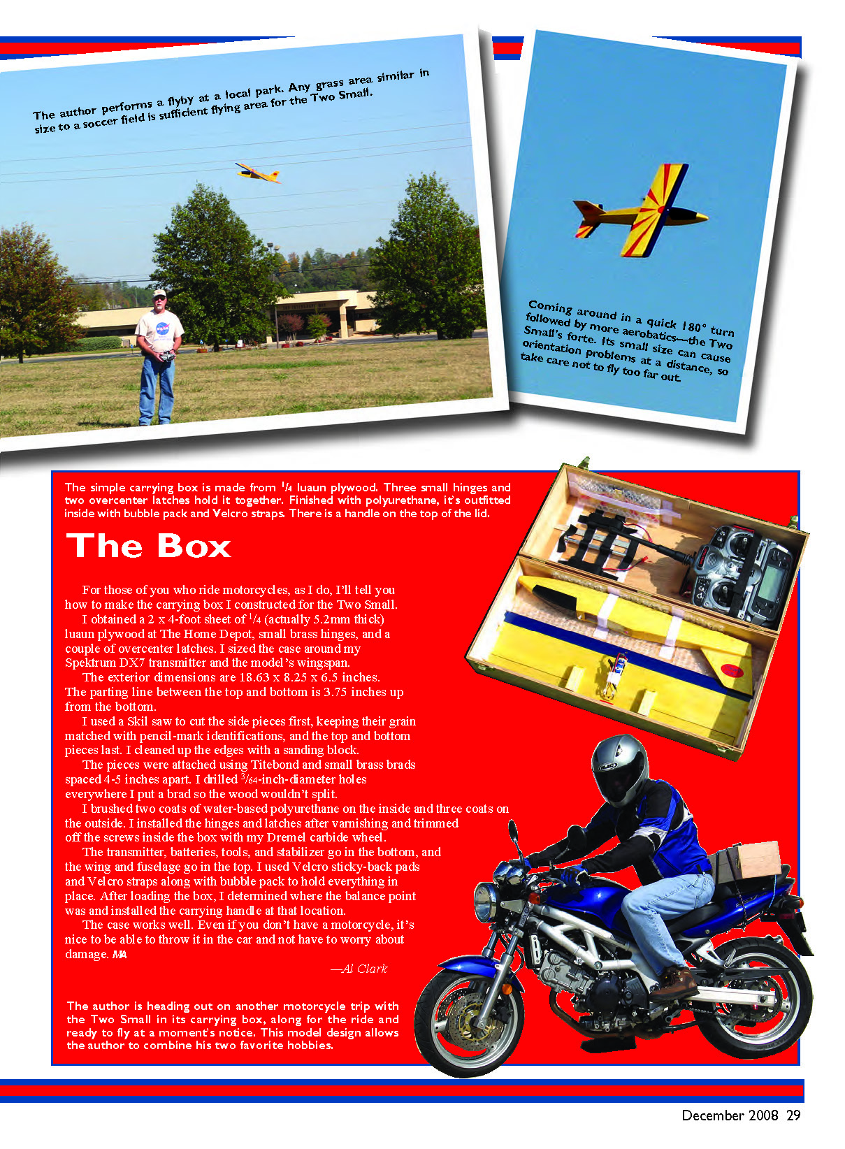
The Two Small is a bit of a hot rod, so it is not suited for beginners. Anyone with some aileron experience on a fairly fast model should have no trouble. Find a nice grass field with a fair amount of space. A soccer field is the minimum; more space would be better for the first flights.
Hand launch the airplane with the motors off (to avoid possibly hitting the pusher propellers). A decent toss at a slight upward angle is best. Immediately after the hand launch, go to full throttle and gain altitude so you can see what trim inputs are required. Don't let the model get too far away; it is easy to lose orientation at a distance. The prototype trimmed out with a tiny amount of up-elevator and approximately 1/64 inch of right aileron.
Two Small is probably going to fly faster than you expected, but you will quickly become accustomed to it; the handling is straightforward, and it doesn't do anything odd or unexpected. The model's size makes it appear faster than it really is. I haven't clocked it, but I estimate it to fly at 35–40 mph. Other fliers who watch swear it is faster than that.
This airplane will perform the usual aerobatics for a model with aileron and elevator control: combinations of looping and rolling maneuvers and hammerhead stalls using engine torque. It is also happy flying inverted and will do nice outside loops.
Landings are easy; just remember that the Two Small covers much more ground than you might be used to, because of its faster-than-normal landing speed. The glide slope is easy to adjust using the throttle, and soon you will be landing the model at your feet. You should get at least 11 minutes of full-throttle airtime using the 2S 700 mAh Li-Poly battery (after the pack is broken in, which takes a few cycles).
I hope you enjoy your Two Small. It is fun for little money, and it seems to be a hit with almost everyone who sees it fly.
—Al Clark [email protected]
Transcribed from original scans by AI. Minor OCR errors may remain.

