
Ultra Micro Diabolo
by John Glezellis [email protected]
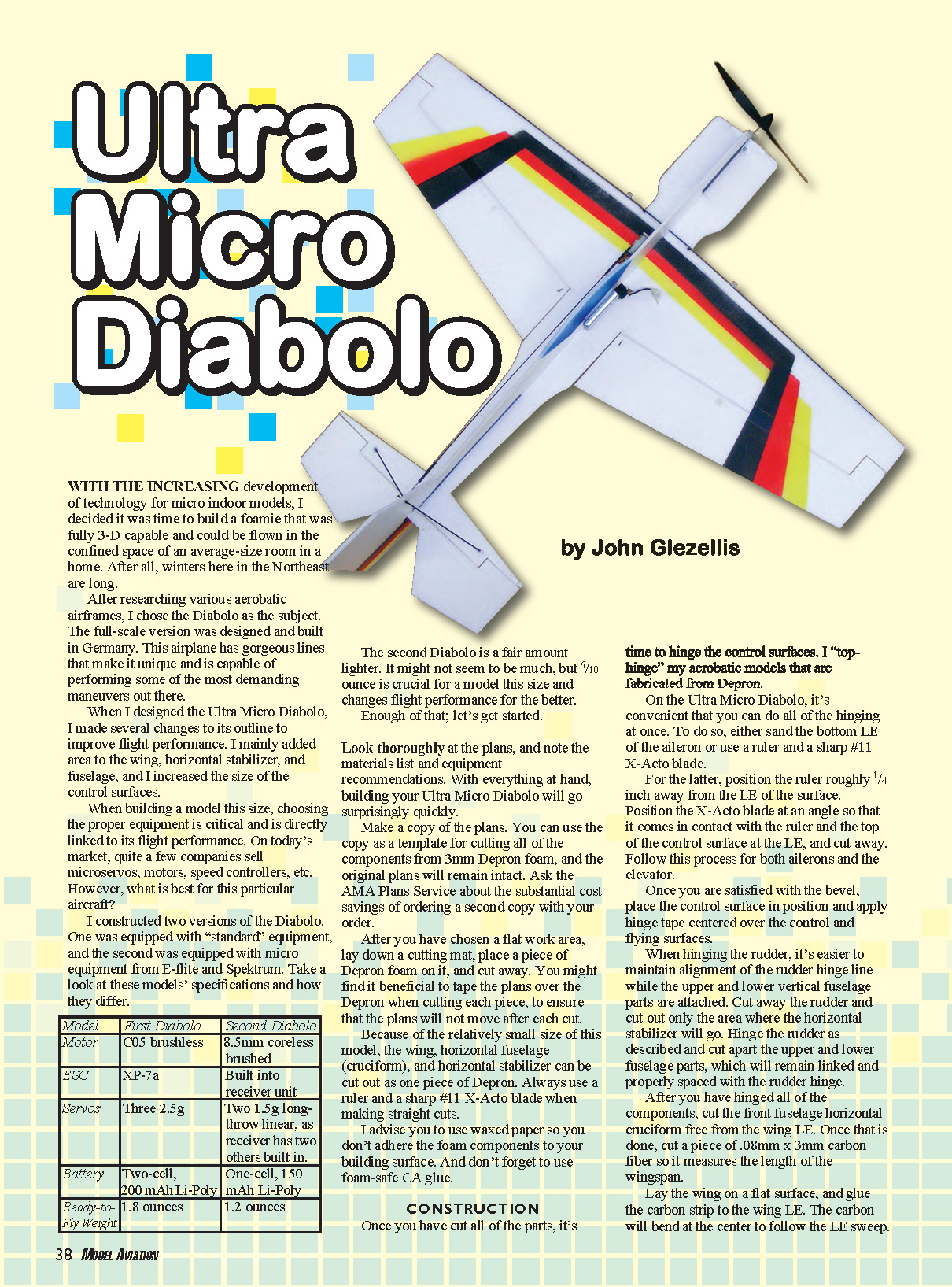
WITH THE INCREASING development of technology for micro indoor models, I decided it was time to build a foamie that was fully 3‑D capable and could be flown in the confined space of an average-size room in a home. After all, winters here in the Northeast are long.
After researching various aerobatic airframes, I chose the Diabolo as the subject. The full‑scale version was designed and built in Germany. This airplane has gorgeous lines that make it unique and is capable of performing some of the most demanding maneuvers out there.
When I designed the Ultra Micro Diabolo, I made several changes to its outline to improve flight performance. I mainly added area to the wing, horizontal stabilizer, and fuselage, and I increased the size of the control surfaces.
When building a model this size, choosing the proper equipment is critical and is directly linked to its flight performance. On today's market, quite a few companies sell micro servos, motors, speed controllers, etc. However, what is best for this particular aircraft?
I constructed two versions of the Diabolo. One was equipped with "standard" equipment, and the second was equipped with micro equipment from E‑flite and Spektrum. Take a look at these models' specifications and how they differ.
- First Diabolo
- Motor: C05 brushless
- ESC: XP‑7a
- Servos: Three 2.5 g
- Battery: Two‑cell, 200 mAh Li‑Poly
- Ready‑to‑Fly Weight: 1.8 ounces
- Second Diabolo
- Motor: 8.5 mm coreless brushed
- ESC: Built into receiver unit
- Servos: Two 1.5 g long‑throw linear; receiver has two others built in
- Battery: One‑cell, 150 mAh Li‑Poly
- Ready‑to‑Fly Weight: 1.2 ounces
The second Diabolo is a fair amount lighter. It might not seem to be much, but 0.6 ounce is crucial for a model this size and changes flight performance for the better. Enough of that; let's get started.
Look thoroughly at the plans, and note the materials list and equipment recommendations. With everything at hand, building your Ultra Micro Diabolo will go surprisingly quickly.
Make a copy of the plans. You can use the copy as a template for cutting all of the components from 3 mm Depron foam, and the original plans will remain intact. Ask the AMA Plans Service about the substantial cost savings of ordering a second copy with your order.
After you have chosen a flat work area, lay down a cutting mat, place a piece of Depron foam on it, and cut away. You might find it beneficial to tape the plans over the Depron when cutting each piece, to ensure that the plans will not move after each cut.
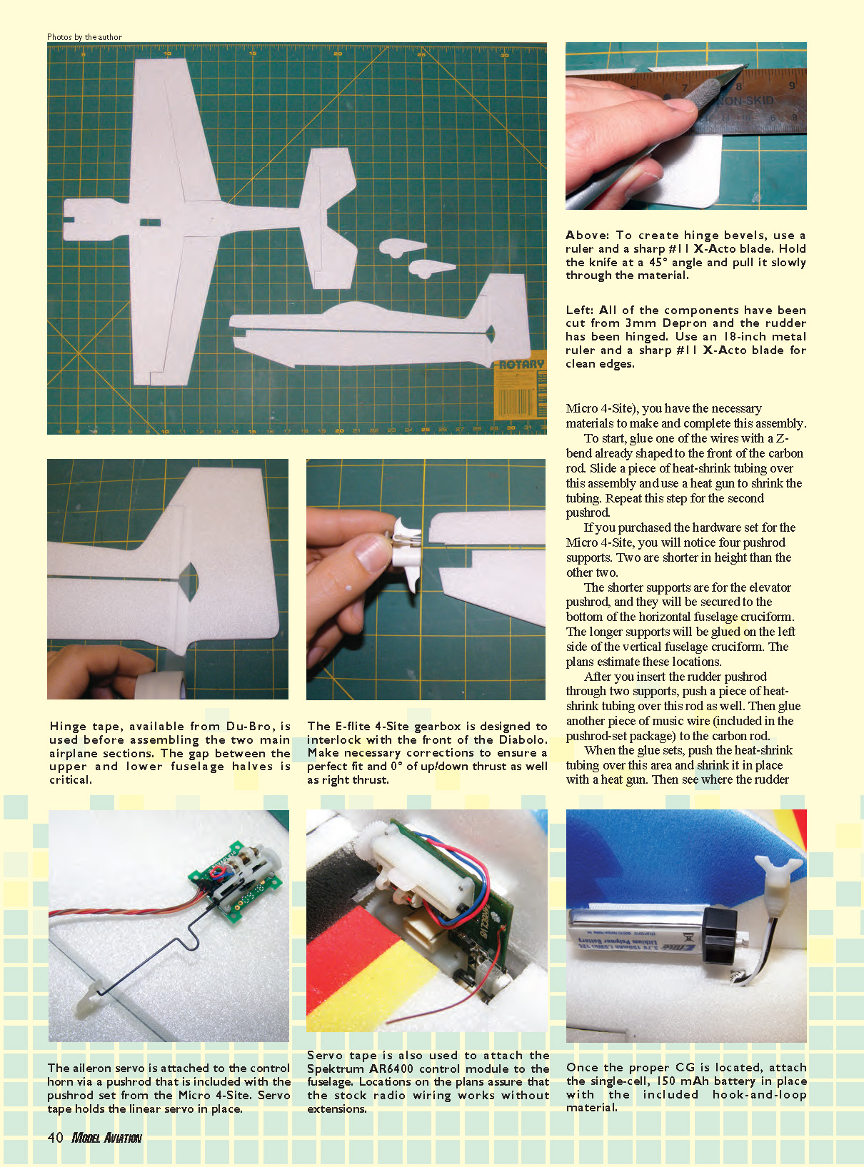
Because of the relatively small size of this model, the wing, horizontal fuselage (cruciform), and horizontal stabilizer can be cut out as one piece of Depron. Always use a ruler and a sharp #11 X‑Acto blade when making straight cuts.
I advise you to use wax paper so you don't adhere the foam components to your building surface. And don't forget to use foam‑safe CA glue.
Construction
Once you have cut all of the parts, it's time to hinge the control surfaces. I "top‑hinge" my aerobatic models that are fabricated from Depron. On the Ultra Micro Diabolo, it's convenient that you can do all of the hinging at once.
To do so, either sand the bottom leading edge (LE) of the aileron or use a ruler and a sharp #11 X‑Acto blade. For the latter, position the ruler roughly 1/4 inch away from the LE of the surface. Position the X‑Acto blade at an angle so that it comes in contact with the ruler and the top of the control surface at the LE, and cut away. Follow this process for both ailerons and the elevator. Once you are satisfied with the bevel, place the control surface in position and apply hinge tape centered over the control and flying surfaces.
When hinging the rudder, it's easier to maintain alignment of the rudder hinge line while the upper and lower vertical fuselage parts are attached. Cut away the rudder and cut out only the area where the horizontal stabilizer will go. Hinge the rudder as described and cut apart the upper and lower fuselage parts, which will remain linked and properly spaced with the rudder hinge.
After you have hinged all of the components, cut the front fuselage horizontal cruciform free from the wing LE. Once that is done, cut a piece of 0.8 mm x 3 mm carbon fiber so it measures the length of the wingspan. Lay the wing on a flat surface, and glue the carbon strip to the wing LE. The carbon will bend at the center to follow the LE sweep.
Once this is complete, glue the front horizontal fuselage cruciform to the center and front of this strip.
If you decide that you want to paint your Diabolo, it is best to do so at this time. If you are using an airbrush, you can employ craft paint (used for T‑shirts, etc.) or any other paint that is compatible with foam.
When choosing a color scheme, I use card stock to make paper templates of the components that are to be painted. Then I draw the scheme on the templates and use an X‑Acto blade to cut out each color that is to be painted. Use a few ounces of weight to hold the template in position over the component and spray away. Remember that patience is a virtue.
Equipment Installation
Before you proceed, decide what electronic equipment you want to put in your little model. As I described, I tested two setups. Because of weight, I recommend that you consider using Spektrum‑brand (or similar) electronics. The build notes below apply to using Spektrum equipment; if you decide on a different brand you might have to modify the equipment installation process on your Diabolo.
Make the appropriate cutout in the wing for the Spektrum AR6400L receiver unit. Once you have completed that, glue the horizontal cruciform assembly (the horizontal fuselage pieces, wing, and horizontal stabilizer) to the vertical fuselage piece. Use an 18‑inch ruler to ensure that the vertical fuselage is properly aligned and a plastic 90° triangle to make sure that the fuselage components are perpendicular to one another.
Once you have completed the assembly process, add the tail bracing made from .040" carbon rod. This will ensure that the horizontal stabilizer will not flex in flight.
It is time to install the landing gear legs and the wheel pants. To do so, cut two pieces of .040" carbon rod that measure 4 1/4 inches in length. Use sandpaper to sharpen one end of each rod.
The plans show where the rods will penetrate both the fuselage side and the wing. Insert the rods through these locations. Once you are satisfied with the height of the model (and make sure it is level), put a few drops of odorless CA where the carbon makes contact with the Depron foam.
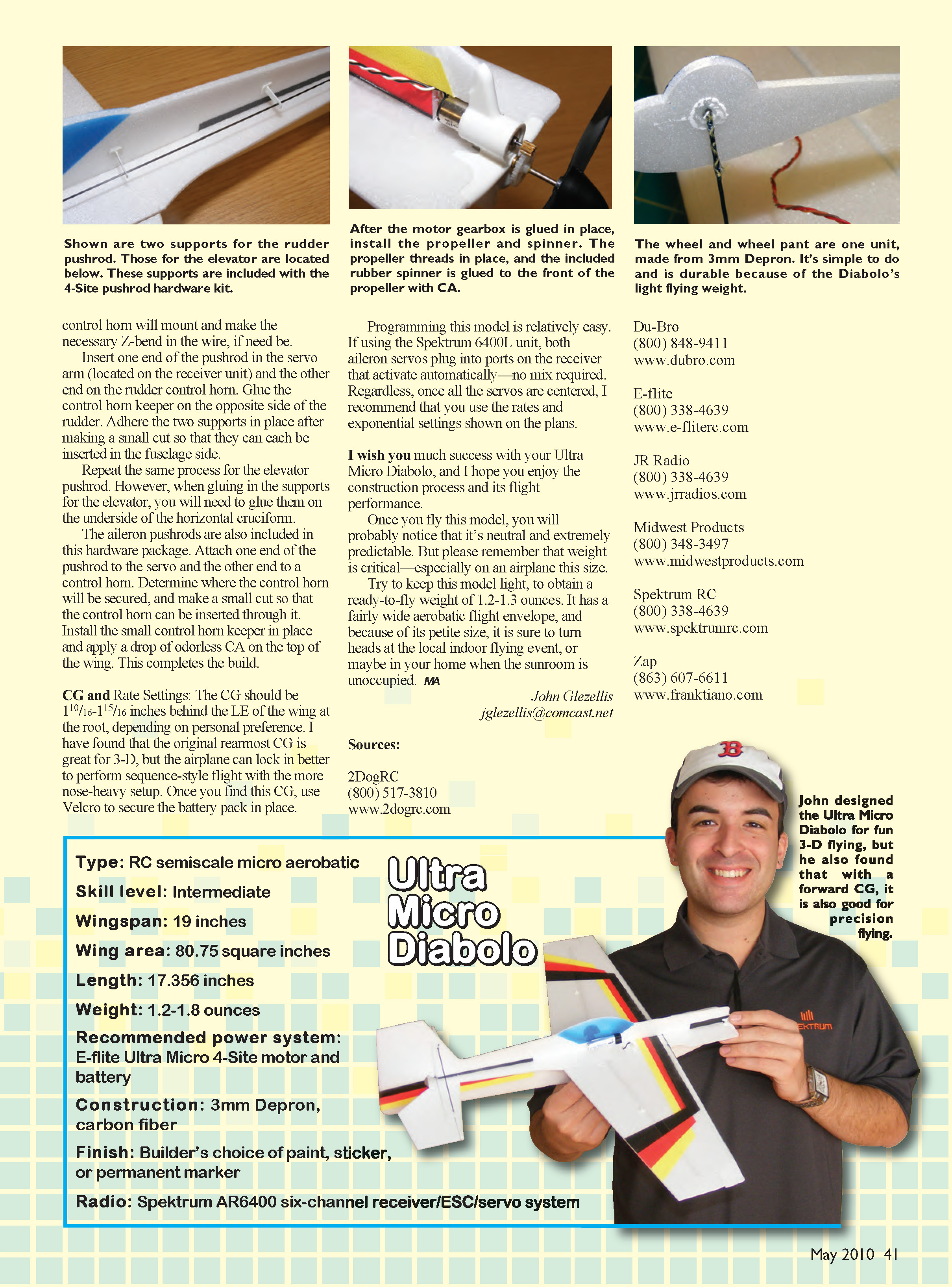
The plans show the wheel pants and wheels as one piece. When you cut the wheel pants, you should also cut a “half wheel” to visually simulate a wheel. This is the lightest method I’ve found to create wheel pants for a model this size. I usually paint the “wheel” so it looks as real as possible.
If you are using this technique, push the carbon‑fiber ends through the wheel pant in the same manner as the landing gear and glue them in place.
Insert the motor into the plastic gearbox. Then insert the entire assembly onto the front of the airplane. It may be necessary to trim the front of the aircraft to accept the gearbox frame. Once the fit is perfect and the motor is properly aligned, glue in the gearbox frame with odorless CA. Last, thread the propeller onto the shaft and use CA to glue the rubber spinner to the front of the propeller.
Install the AR6400L receiver unit and the two wing servos using double‑stick servo tape. Cut a small piece of servo tape that is slightly smaller than each servo, and place it on the underside of the servo. Position the servos according to the plans and properly secure them.
For the AR6400L, cut two strands of servo tape (measuring 1/4 x 3/4 inch) and secure them lengthwise on the top and bottom of the underside of the unit. Then secure the AR6400L in place.
When I installed my unit, I plugged the motor into the receiver and ran the motor on the bench before I installed the propeller. Doing so ensured a smooth installation with respect to the motor.
The pushrods on my model measure 10 1/8 inches for both the rudder and the elevator. If you purchased the pushrod set (for the E‑flite servos), follow the manufacturer’s instructions for clevis and connector installation. If you purchased the hardware set for the Ultra Micro 4‑Site, you have the necessary materials to make and complete this assembly.
To start, glue one of the wires with a Z‑bend already shaped to the front of the carbon rod. Slide a piece of heat‑shrink tubing over this assembly and use a heat gun to shrink the tubing. Repeat this step for the second pushrod.
If you purchased the hardware set for the Ultra Micro 4‑Site, you will notice four pushrod supports. Two are shorter in height than the other two. The shorter supports are for the elevator pushrod, and they will be secured to the bottom of the horizontal fuselage cruciform. The longer supports will be glued on the left side of the vertical fuselage cruciform. The plans estimate these locations.
After you insert the rudder pushrod through two supports, push a piece of heat‑shrink tubing over this rod as well. Then glue another piece of music wire (included in the pushrod‑set package) to the carbon rod. When the glue sets, push the heat‑shrink tubing over this area and shrink it in place with a heat gun. Then see where the rudder control horn will mount and make the necessary Z‑bend in the wire, if need be.
Insert one end of the pushrod in the servo arm (located on the receiver unit) and the other end on the rudder control horn. Glue the control horn keeper on the opposite side of the rudder. Adhere the two supports in place after making a small cut so that they can each be inserted in the fuselage side.
Repeat the same process for the elevator pushrod. However, when gluing in the supports for the elevator, glue them on the underside of the horizontal cruciform.
The aileron pushrods are also included in this hardware package. Attach one end of the pushrod to the servo and the other end to a control horn. Determine where the control horn will be secured, and make a small cut so that the control horn can be inserted through it. Install the small control horn keeper in place and apply a drop of odorless CA on the top of the wing. This completes the build.
CG and Rate Settings
- Center of Gravity (CG): 1 1/16 – 1 15/16 inches behind the LE of the wing at the root, depending on personal preference. The original rearmost CG is great for 3‑D; a more nose‑heavy setup locks in better for sequence‑style flight.
- Secure the battery pack with Velcro once the CG is set.
Programming this model is relatively easy. If using the Spektrum AR6400L unit, both aileron servos plug into ports on the receiver that activate automatically—no mix required. Regardless, once all the servos are centered, use the rates and exponential settings shown on the plans.
I wish you much success with your Ultra Micro Diabolo, and I hope you enjoy the construction process and its flight performance.
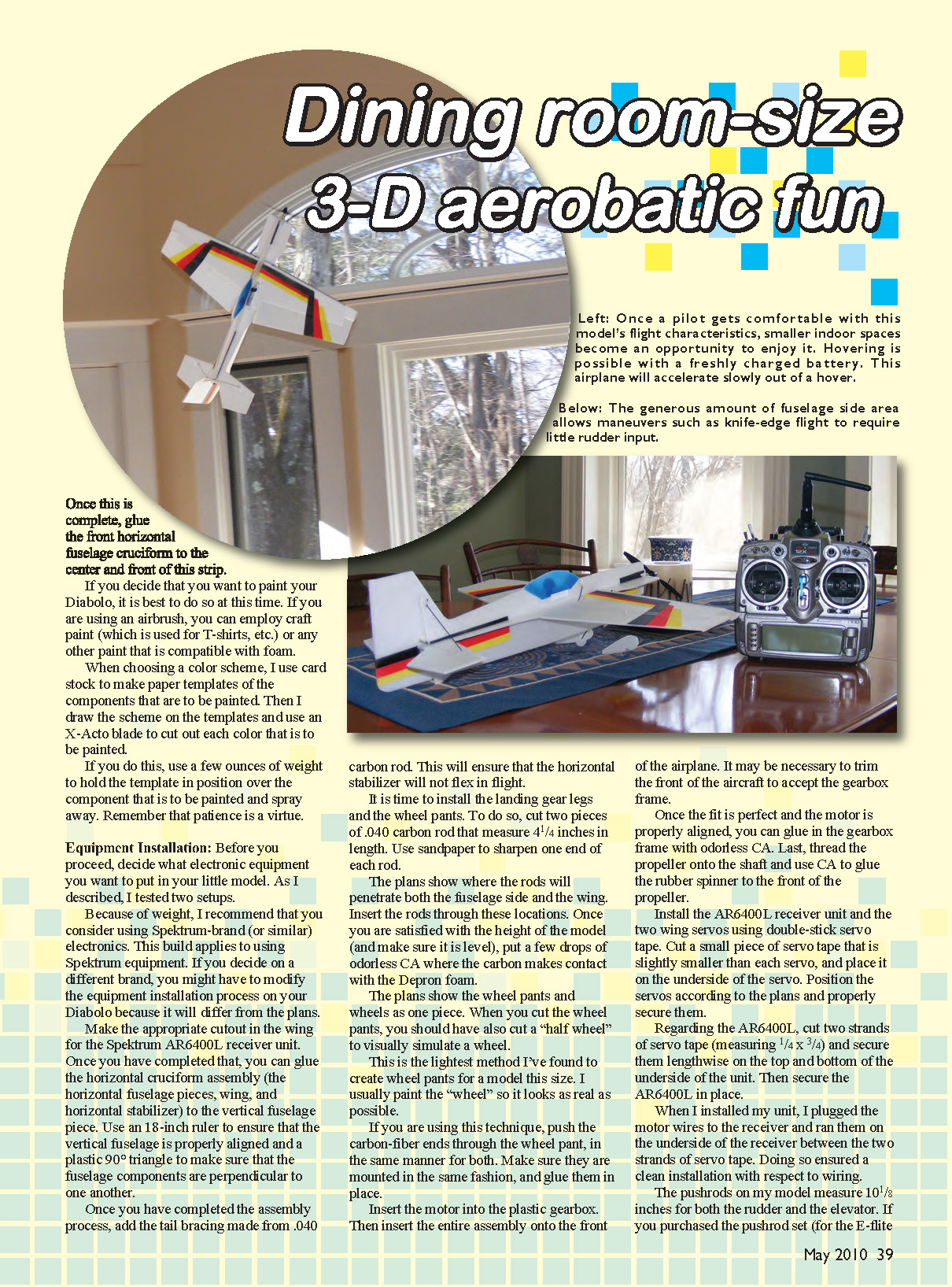
Once you fly this model, you will probably notice that it's neutral and extremely predictable. But please remember that weight is critical—especially on an airplane this size. Try to keep this model light, to obtain a ready‑to‑fly weight of 1.2–1.3 ounces. It has a fairly wide aerobatic flight envelope, and because of its petite size, it is sure to turn heads at the local indoor flying event, or maybe in your home when the sunroom is unoccupied.
MA
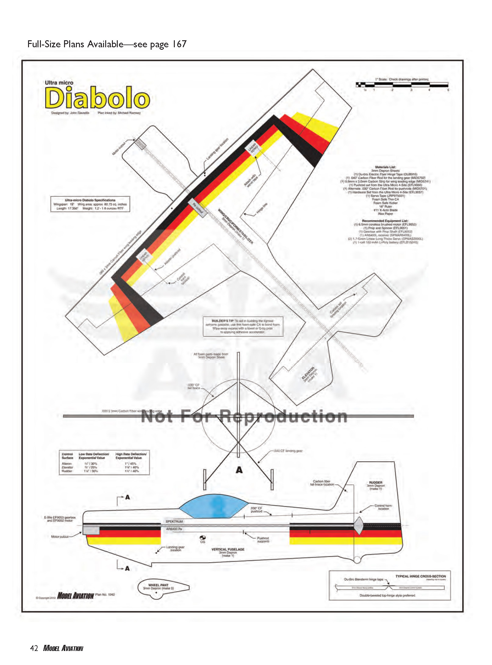
Ultra‑micro Diabolo Specifications
- Wingspan: 17"
- Wing area: approx. 80.75 sq. in.
- Length: 17.356"
- Weight: 1.2–1.8 ounces RTF
Materials List
- 3 mm Depron sheets
- (1) Du‑Bro Electric Flyer hinge tape (DUB916)
- (1) .040" carbon fiber rod for the landing gear (MID5727)
- (1) 0.8 mm x 3.0 mm carbon strip for wing leading edge (MID6741)
- (1) Pushrod set from the Ultra Micro 4‑Site (EFL9056)
- (1) Alternate .030" carbon fiber rod for pushrods (MID5701)
- (1) Hardware set from the Ultra Micro 4‑Site (EFL9057)
- (1) Servo tape (JRP975031)
- Foam‑safe thin CA
- Foam‑safe kicker
- 18" ruler
- #11 X‑Acto blade
- Wax paper
- Heat‑shrink tubing
- Odorless CA
- Music wire (included in pushrod/hardware set)
Recommended Equipment List
- (1) 6.5 mm coreless brushed motor (EFL9052)
- (1) Prop and spinner (EFL9051)
- (1) Gearbox with prop shaft (EFL9053)
- (1) AR6400 receiver
- (2) 1.7‑gram long‑throw servos
- (1) 1‑cell 150 mAh Li‑Po battery (EFLB1505S)
Builders tip: To aid in making the forward surfaces removable, use thin foam‑safe CA to bond foam. Wipe away excess with a towel or Q‑tip prior to applying an adhesive accelerator.
Wheel Pant / Parts Callouts
- Wheel pant: 3 mm Depron (make 2)
- Vertical fuselage: 3 mm Depron (make 1)
- Rudder: 3 mm Depron (make 1) — control horn location indicated on plan
- Typical hinge cross‑section: Du‑Bro E‑Flite hinge tape recommended; double‑beveled top‑hinge style preferred
Control Surface Deflection / Exponential Values
- Aileron: Low rate 1/2" / 20% exp ; High rate 1‑1/8" / 45% exp
- Elevator: Low rate 1/2" / 25% exp ; High rate 1‑1/4" / 45% exp
- Rudder: Low rate 1/2" / 30% exp ; High rate 1‑1/8" / 40% exp
Sources
- 2DogRC — (800) 517‑3810 — www.2dogrc.com
- Du‑Bro — (800) 848‑9411 — www.dubro.com
- E‑flite — (800) 338‑4639 — www.e‑flite.com
- JR Radio — (800) 338‑4639 — www.jrradios.com
- Midwest Products — (800) 348‑3497 — www.midwestproducts.com
- Spektrum RC — (800) 338‑4639 — www.spektrumrc.com
- Zap — (863) 607‑6611 — www.franktiano.com
Transcribed from original scans by AI. Minor OCR errors may remain.

